
Operation Guide
Page 54
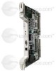
... is located above the alarm pin field on the fan tray will go blank. 1-16 Cisco ONS 15454 Installation and Operations Guide November 2001 See the "Install the Fan-Tray Assembly" procedure on the AIP board can cause the LCD display to store the node database. It allows CTC to the fan... non-volatile memory chip that stores the unique node address (MAC address). Grasp the clear plastic cover at each side. The Timing Communication and Control+ (TCC+) cards in place with two retaining screws. If the AIP fails, a MAC Fail alarm displays on the CTC Alarms menu and/or the LCD display on...
... is located above the alarm pin field on the fan tray will go blank. 1-16 Cisco ONS 15454 Installation and Operations Guide November 2001 See the "Install the Fan-Tray Assembly" procedure on the AIP board can cause the LCD display to store the node database. It allows CTC to the fan... non-volatile memory chip that stores the unique node address (MAC address). Grasp the clear plastic cover at each side. The Timing Communication and Control+ (TCC+) cards in place with two retaining screws. If the AIP fails, a MAC Fail alarm displays on the CTC Alarms menu and/or the LCD display on...
Operation Guide
Page 55
...Side A and BNC on Side B or High-Density BNC on side A and SMB on the EIA board. Figure 1-39 shows the ONS 15454 with SMB and BNC connectors for DS-1 cards. This section describes each EIA and provides installation procedures. The BNC connectors on page 1-36. EIAs are...32 x 1/2 inch phillips screw holes so you are available with pre-installed BNC EIAs. For information about attaching ferrites to the Cisco ONS 15454 Troubleshooting and Maintenance Guide. EIAs are installing EIAs after the shelf assembly is installed, plug the EIA into six corresponding backplane connectors. ...
...Side A and BNC on Side B or High-Density BNC on side A and SMB on the EIA board. Figure 1-39 shows the ONS 15454 with SMB and BNC connectors for DS-1 cards. This section describes each EIA and provides installation procedures. The BNC connectors on page 1-36. EIAs are...32 x 1/2 inch phillips screw holes so you are available with pre-installed BNC EIAs. For information about attaching ferrites to the Cisco ONS 15454 Troubleshooting and Maintenance Guide. EIAs are installing EIAs after the shelf assembly is installed, plug the EIA into six corresponding backplane connectors. ...

Operation Guide
Page 370
... if any node on the network. The Inherited profile is blown. Figure 10-6 illustrates the LCD panel. Use the Port button to toggle to any alarms are independent of the Card, Port, and Status indicators on the AIP board is not available at the node level. 10-8 Cisco ONS 15454 Installation and Operations Guide November...
... if any node on the network. The Inherited profile is blown. Figure 10-6 illustrates the LCD panel. Use the Port button to toggle to any alarms are independent of the Card, Port, and Status indicators on the AIP board is not available at the node level. 10-8 Cisco ONS 15454 Installation and Operations Guide November...