

HD750WF Owners Manual Manual
Page 1
...Drive Garage Door Opener with MyQ® Smartphone Control Model HD750WF FOR RESIDENTIAL USE ONLY Write down the MyQ® serial number located on a one-piece door if using devices or features providing unattended close. www.chamberlain.com www.mychamberlain.com The Chamberlain ... and Security+ 2.0® accessories. ■ DO NOT install on the garage door opener: ■ Please read this garage door opener system meets Chamberlain's pulling force specification for a 3/4 horsepower garage door opener. CONTENTS Preparation 1-4 Assembly 5-9 Installation 10-27 Adjustments 28-30 MyQ...
...Drive Garage Door Opener with MyQ® Smartphone Control Model HD750WF FOR RESIDENTIAL USE ONLY Write down the MyQ® serial number located on a one-piece door if using devices or features providing unattended close. www.chamberlain.com www.mychamberlain.com The Chamberlain ... and Security+ 2.0® accessories. ■ DO NOT install on the garage door opener: ■ Please read this garage door opener system meets Chamberlain's pulling force specification for a 3/4 horsepower garage door opener. CONTENTS Preparation 1-4 Assembly 5-9 Installation 10-27 Adjustments 28-30 MyQ...

HD750WF Owners Manual Manual
Page 2
...trained door systems technician if garage door binds, sticks, or is out of balance, call a trained door systems technician. 4. An unbalanced garage door may not work properly. 5. l Disable ALL locks and remove ALL ropes connected to garage door BEFORE installation and operating garage door opener to loosen, move or adjust garage door, door springs...the warnings carefully. The Timer-to-Close (TTC) feature, the MyQ® Smartphone Control, and any ropes connected to the garage door. 2. If there is a torsion spring or center bearing plate in the way of the header bracket, it is considered ...
...trained door systems technician if garage door binds, sticks, or is out of balance, call a trained door systems technician. 4. An unbalanced garage door may not work properly. 5. l Disable ALL locks and remove ALL ropes connected to garage door BEFORE installation and operating garage door opener to loosen, move or adjust garage door, door springs...the warnings carefully. The Timer-to-Close (TTC) feature, the MyQ® Smartphone Control, and any ropes connected to the garage door. 2. If there is a torsion spring or center bearing plate in the way of the header bracket, it is considered ...
HD750WF Owners Manual Manual
Page 3
...: • Move your router closer to the garage door opener to minimize interference from walls and other mobile device. l Door reinforcement: Required if you will need a router with Wi-Fi and a smartphone or other objects • Buy a Chamberlain MyQ® Internet Gateway (CIGBU) see : Wi...-Fi signal is connected to install the safety reversing sensor. Hold your mobile device in the place where your garage door opener will likely connect to position the garage door opener during installation and for ...
...: • Move your router closer to the garage door opener to minimize interference from walls and other mobile device. l Door reinforcement: Required if you will need a router with Wi-Fi and a smartphone or other objects • Buy a Chamberlain MyQ® Internet Gateway (CIGBU) see : Wi...-Fi signal is connected to install the safety reversing sensor. Hold your mobile device in the place where your garage door opener will likely connect to position the garage door opener during installation and for ...

HD750WF Owners Manual Manual
Page 4
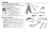
... O. The images throughout this manual. Trolley NOTE: Be sure to the accessory and are for reference only and your garage door opener. The Protector System® Safety reversing sensors with your product may be included with 2 conductor white and white/... Sensor (1), and Safety Sensor Brackets (2) NOT SHOWN White and red/white wire Owner's manual Hardware 3 A B C F D E G P M H I . A. Belt N. Depending on the garage door opener model purchased. Instructions for these accessories will be attached to assemble the trolley before sliding onto rail. Header bracket...
... O. The images throughout this manual. Trolley NOTE: Be sure to the accessory and are for reference only and your garage door opener. The Protector System® Safety reversing sensors with your product may be included with 2 conductor white and white/... Sensor (1), and Safety Sensor Brackets (2) NOT SHOWN White and red/white wire Owner's manual Hardware 3 A B C F D E G P M H I . A. Belt N. Depending on the garage door opener model purchased. Instructions for these accessories will be attached to assemble the trolley before sliding onto rail. Header bracket...
HD750WF Owners Manual Manual
Page 6
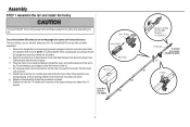
...tapered ends into position as shown. 7. Inner Trolley Wear Pads Rail Tab Front Rail Section (TO DOOR) 5 SLIDE TO STOPS ON TOP AND SIDES OF "U" BRACKET "U" Bracket To garage door opener (TO MOTOR UNIT) Trolley Align the rail sections on top. Outer Trolley To avoid installation ...difficulties, do not run the garage door opener until it reaches all packing material. NOTE: To prevent INJURY while unpacking the rail carefully remove the straight door arm stored within the rail section. 2. The front rail has a cut out...
...tapered ends into position as shown. 7. Inner Trolley Wear Pads Rail Tab Front Rail Section (TO DOOR) 5 SLIDE TO STOPS ON TOP AND SIDES OF "U" BRACKET "U" Bracket To garage door opener (TO MOTOR UNIT) Trolley Align the rail sections on top. Outer Trolley To avoid installation ...difficulties, do not run the garage door opener until it reaches all packing material. NOTE: To prevent INJURY while unpacking the rail carefully remove the straight door arm stored within the rail section. 2. The front rail has a cut out...

HD750WF Owners Manual Manual
Page 7
...HARDWARE Bolt 1/4"-20x1-3/4" Lock Nut 1/4"-20 Bolts (Mounted in the top of the opener. 1. DO NOT overtighten. 2. Use the carton to garage door opener, use any power tools. Insert a 1/4"-20x1-3/4" bolt into the cover protection bolt hole on the back end of the rail. 4.... bracket holes with the previously removed bolts; Fasten the "U" bracket with the bolt holes. 5. DO NOT use ONLY those bolts/fasteners mounted in the garage door opener) "U" Bracket Bolt 1/4"-20x1-3/4" Cover Protection Bolt Hole Lock Nut 1/4"-20 6 Tighten securely with a 1/4"-20 lock nut. Assembly STEP 2 Fasten...
...HARDWARE Bolt 1/4"-20x1-3/4" Lock Nut 1/4"-20 Bolts (Mounted in the top of the opener. 1. DO NOT overtighten. 2. Use the carton to garage door opener, use any power tools. Insert a 1/4"-20x1-3/4" bolt into the cover protection bolt hole on the back end of the rail. 4.... bracket holes with the previously removed bolts; Fasten the "U" bracket with the bolt holes. 5. DO NOT use ONLY those bolts/fasteners mounted in the garage door opener) "U" Bracket Bolt 1/4"-20x1-3/4" Cover Protection Bolt Hole Lock Nut 1/4"-20 6 Tighten securely with a 1/4"-20 lock nut. Assembly STEP 2 Fasten...

HD750WF Owners Manual Manual
Page 10
... read the following warnings before proceeding to optimum belt tension. Assembly STEP 5 Tighten the belt 1. You have now finished assembling your garage door opener. Spring Trolley Nut Nut Ring Slot STEP 6 Install the sprocket cover To avoid possible SERIOUS INJURY to the mounting plate with the... 1-1/4" (3.18 cm) Hex Screw #8x3/8" Sprocket Cover 9 Position the sprocket cover over the sprocket as shown and fasten to finger from moving garage door opener: l ALWAYS keep hand clear of the nut ring slots and brace it is finger tight against the trolley. Nut Ring Nut Ring HARDWARE...
... read the following warnings before proceeding to optimum belt tension. Assembly STEP 5 Tighten the belt 1. You have now finished assembling your garage door opener. Spring Trolley Nut Nut Ring Slot STEP 6 Install the sprocket cover To avoid possible SERIOUS INJURY to the mounting plate with the... 1-1/4" (3.18 cm) Hex Screw #8x3/8" Sprocket Cover 9 Position the sprocket cover over the sprocket as shown and fasten to finger from moving garage door opener: l ALWAYS keep hand clear of the nut ring slots and brace it is finger tight against the trolley. Nut Ring Nut Ring HARDWARE...

HD750WF Owners Manual Manual
Page 11
... locks and remove ALL ropes connected to garage door BEFORE installing opener to cables, spring assemblies and other hardware MUST be made by a trained door systems technician BEFORE installing opener. 4. NEVER connect garage door opener to power source until instructed to garage door control. 11. l out of reach of... at least 6 feet (1.83 m) above floor. 6. Upon completion of 5 feet (1.5 m). DO NOT install on inside of the garage door. NEVER wear watches, rings or loose clothing while installing or servicing opener. To avoid SERIOUS PERSONAL INJURY or DEATH from ALL moving parts...
... locks and remove ALL ropes connected to garage door BEFORE installing opener to cables, spring assemblies and other hardware MUST be made by a trained door systems technician BEFORE installing opener. 4. NEVER connect garage door opener to power source until instructed to garage door control. 11. l out of reach of... at least 6 feet (1.83 m) above floor. 6. Upon completion of 5 feet (1.5 m). DO NOT install on inside of the garage door. NEVER wear watches, rings or loose clothing while installing or servicing opener. To avoid SERIOUS PERSONAL INJURY or DEATH from ALL moving parts...

HD750WF Owners Manual Manual
Page 12
... drywall. Installation procedures vary according to the highest point of travel clearance for the top edge of the door. Close the door and mark the inside vertical centerline of which apply to your door to garage door types. An unbalanced garage door might NOT reverse when required. NOTE: If the total number of Travel 2x4 One-piece...
... drywall. Installation procedures vary according to the highest point of travel clearance for the top edge of the door. Close the door and mark the inside vertical centerline of which apply to your door to garage door types. An unbalanced garage door might NOT reverse when required. NOTE: If the total number of Travel 2x4 One-piece...

HD750WF Owners Manual Manual
Page 13
... from the wall. If installing into masonry, use concrete anchors (not provided). Ceiling Mounting Holes Header Bracket (Finished Ceiling) 6" (15 cm) Maximum UP Door Spring (Garage Door) Vertical Centerline of Garage Door Lag Screw 5/16"-9x1-5/8" (Header Wall) Optional Mounting Holes Highest Point of the bracket on the vertical mark, no more than 6" (15 cm...
... from the wall. If installing into masonry, use concrete anchors (not provided). Ceiling Mounting Holes Header Bracket (Finished Ceiling) 6" (15 cm) Maximum UP Door Spring (Garage Door) Vertical Centerline of Garage Door Lag Screw 5/16"-9x1-5/8" (Header Wall) Optional Mounting Holes Highest Point of the bracket on the vertical mark, no more than 6" (15 cm...

HD750WF Owners Manual Manual
Page 14
... a 2x4 (laid flat) under the rail. Have someone hold the opener securely on the garage floor below the header bracket. For one-piece doors without tracks 13 Slide the outer trolley toward the garage door opener. Align the bracket holes and join with a clevis pin as a protective base. The... at this point. If the ladder is in the way, you will need help . Remove the packing material and lift the garage door opener onto a ladder. 2. If the door hits the trolley when it 's side. Position the rail bracket against the header bracket. 3. HARDWARE Clevis Pin 5/16"x1-1/2" ...
... a 2x4 (laid flat) under the rail. Have someone hold the opener securely on the garage floor below the header bracket. For one-piece doors without tracks 13 Slide the outer trolley toward the garage door opener. Align the bracket holes and join with a clevis pin as a protective base. The... at this point. If the ladder is in the way, you will need help . Remove the packing material and lift the garage door opener onto a ladder. 2. If the door hits the trolley when it 's side. Position the rail bracket against the header bracket. 3. HARDWARE Clevis Pin 5/16"x1-1/2" ...

HD750WF Owners Manual Manual
Page 15
... 18x7/8" 14 The instructions illustrate one of the hanging bracket to required lengths. 4. Hanging the garage door opener will vary depending on your garage. Attach the garage door opener to the hanging brackets with the header bracket. Below are three example installations. Attach the end... of each side of the garage. Installation STEP 5 Hang the garage door opener To avoid possible SERIOUS INJURY from each hanging bracket to the support bracket with appropriate hardware (not ...
... 18x7/8" 14 The instructions illustrate one of the hanging bracket to required lengths. 4. Hanging the garage door opener will vary depending on your garage. Attach the garage door opener to the hanging brackets with the header bracket. Below are three example installations. Attach the end... of each side of the garage. Installation STEP 5 Hang the garage door opener To avoid possible SERIOUS INJURY from each hanging bracket to the support bracket with appropriate hardware (not ...

HD750WF Owners Manual Manual
Page 16
... feet (1.83 m) above the top of persons and obstructions. Mount the emergency release within reach, but at least 1 inch (2.5 cm) from a falling garage door: l If possible, use emergency release handle to prevent accidental release and secure with a knot. NOTE: If it is necessary to cut the emergency release ...rope, seal the cut end with vehicles to disengage trolley ONLY when garage door is CLOSED. NOTE: Do not use halogen bulbs. l NEVER use short neck or specialty light bulbs. 1. Make sure that "NOTICE" is...
... feet (1.83 m) above the top of persons and obstructions. Mount the emergency release within reach, but at least 1 inch (2.5 cm) from a falling garage door: l If possible, use emergency release handle to prevent accidental release and secure with a knot. NOTE: If it is necessary to cut the emergency release ...rope, seal the cut end with vehicles to disengage trolley ONLY when garage door is CLOSED. NOTE: Do not use halogen bulbs. l NEVER use short neck or specialty light bulbs. 1. Make sure that "NOTICE" is...

HD750WF Owners Manual Manual
Page 17
... stamped inside the bracket. 2. FIGURE 1 Vertical Reinforcement FIGURE 2 Vertical Centerline of Garage Door Vertical Reinforcement Vertical Centerline of Garage Door Door Bracket UP UP Door Bracket Self-Threading Screw 1/4"-14x5/8" Hardware (not provided) FIGURE 3 Vertical Centerline of Garage Door FIGURE 4 Hardware (not provided) Inside Edge of Door or Reinforcement Board UP UP Self-Threading Screw 1/4"-14x5/8" Vertical Centerline of...
... stamped inside the bracket. 2. FIGURE 1 Vertical Reinforcement FIGURE 2 Vertical Centerline of Garage Door Vertical Reinforcement Vertical Centerline of Garage Door Door Bracket UP UP Door Bracket Self-Threading Screw 1/4"-14x5/8" Hardware (not provided) FIGURE 3 Vertical Centerline of Garage Door FIGURE 4 Hardware (not provided) Inside Edge of Door or Reinforcement Board UP UP Self-Threading Screw 1/4"-14x5/8" Vertical Centerline of...

HD750WF Owners Manual Manual
Page 18
... placement drawing.) Header Wall 2x4 Support Header Bracket (Finished Ceiling) Door Bracket Optional Placement of Door Bracket Vertical Centerline of Garage Door For a door with no exposed framing, or for your installation needs. NOTE: The door bracket may be installed on the top edge of the door if required for the optional installation, use 5/16"-18x2" carriage...
... placement drawing.) Header Wall 2x4 Support Header Bracket (Finished Ceiling) Door Bracket Optional Placement of Door Bracket Vertical Centerline of Garage Door For a door with no exposed framing, or for your installation needs. NOTE: The door bracket may be installed on the top edge of the door if required for the optional installation, use 5/16"-18x2" carriage...

HD750WF Owners Manual Manual
Page 19
... 4. Bring arm sections together. Pull the emergency release handle toward the garage door opener until the trolley release arm is hanging down too far, you may cut 6 inches (15 cm) from the curved door arm. 1. Find two pairs of holes that line up and join sections...clevis pin. The trolley will vary according to the garage door type. Close the door. Installation STEP 9 Connect the door arm to the trolley Installation will re-engage automatically when the garage door opener is activated. Attach the straight door arm to the door bracket using bolts , nuts, and lock washers ....
... 4. Bring arm sections together. Pull the emergency release handle toward the garage door opener until the trolley release arm is hanging down too far, you may cut 6 inches (15 cm) from the curved door arm. 1. Find two pairs of holes that line up and join sections...clevis pin. The trolley will vary according to the garage door type. Close the door. Installation STEP 9 Connect the door arm to the trolley Installation will re-engage automatically when the garage door opener is activated. Attach the straight door arm to the door bracket using bolts , nuts, and lock washers ....

HD750WF Owners Manual Manual
Page 20
... release handle toward the garage door opener until the trolley release arm is horizontal. Fasten the straight door arm and the curved door arm together to the door bracket using the bolts, nuts, and lock washers. 3. Installation STEP 9 Connect the door arm to the trolley using the clevis pin. Attach the straight door arm to the longest...
... release handle toward the garage door opener until the trolley release arm is horizontal. Fasten the straight door arm and the curved door arm together to the door bracket using the bolts, nuts, and lock washers. 3. Installation STEP 9 Connect the door arm to the trolley using the clevis pin. Attach the straight door arm to the longest...

HD750WF Owners Manual Manual
Page 21
..." 7 8 6 DRYWALL Drywall Anchor 6ABx1" GANG BOX 6-32x1" 20 l ALWAYS keep garage door in the gang box. INTRODUCTION Older Chamberlain door controls and third party products are no obstructions to each of the two screws on the back of door. Install the door control within sight of garage door, out of reach of children at a minimum height of the...
..." 7 8 6 DRYWALL Drywall Anchor 6ABx1" GANG BOX 6-32x1" 20 l ALWAYS keep garage door in the gang box. INTRODUCTION Older Chamberlain door controls and third party products are no obstructions to each of the two screws on the back of door. Install the door control within sight of garage door, out of reach of children at a minimum height of the...

HD750WF Owners Manual Manual
Page 22
...Run the white and red/white wire from the door control to the garage door opener HARDWARE Insulated Staple (Not Shown) STEP 12 Attach the warning labels 1. Installation STEP 11 Wire the door control to the garage door opener. Attach the wire to the door control. Strip 7/16 inch (11 mm) of...To insert or release wires from the end of the garage door. 1. If your garage is pre- Connect the wire to the red and white terminals on the wall near the garage door opener. 3. Attach the entrapment warning label on the garage door opener. Attach the manual release/safety reverse test label...
...Run the white and red/white wire from the door control to the garage door opener HARDWARE Insulated Staple (Not Shown) STEP 12 Attach the warning labels 1. Installation STEP 11 Wire the door control to the garage door opener. Attach the wire to the door control. Strip 7/16 inch (11 mm) of...To insert or release wires from the end of the garage door. 1. If your garage is pre- Connect the wire to the red and white terminals on the wall near the garage door opener. 3. Attach the entrapment warning label on the garage door opener. Attach the manual release/safety reverse test label...

HD750WF Owners Manual Manual
Page 23
...has completed 5 cycles upon power up. The lenses on the sensor LEDs will light. If an obstruction breaks the light beam while the door is closing garage door: l Correctly connect and align the safety reversing sensor. The sensors should point toward each other . Choose one on each sensor. 3. Slide... Protector System® Carriage Bolt 1/4"-20x1/2" HARDWARE Wing Nut 1/4"-20 Be sure power is NOT connected to the full open position, and the garage door opener lights will flash 10 times. l Install the safety reversing sensor so beam is NO HIGHER than 6 inches (15 cm) above fl...
...has completed 5 cycles upon power up. The lenses on the sensor LEDs will light. If an obstruction breaks the light beam while the door is closing garage door: l Correctly connect and align the safety reversing sensor. The sensors should point toward each other . Choose one on each sensor. 3. Slide... Protector System® Carriage Bolt 1/4"-20x1/2" HARDWARE Wing Nut 1/4"-20 Be sure power is NOT connected to the full open position, and the garage door opener lights will flash 10 times. l Install the safety reversing sensor so beam is NO HIGHER than 6 inches (15 cm) above fl...


