
Maintenance Schedule - English
Page 4
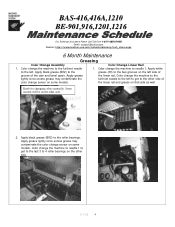
... to needle 1. Color change the machine to needle 1 to get to 4 roller bearings on the left . Knob for changing colors manually. Color change the machine to the lightly since excess grease may contaminate the furthest needle to the left to get to the last 3... grease (BR2) to the grease (30) to the furthest needle 1. BAS-416,416A,1210 BE-901,916,1201,1216 For Technical As sistance Please Call Toll Free 1-877-4BROTHER Email: tsupport@brother.com Website: http://www.brother-usa.com/industembroidery/tech_down.aspx 6 Month Maintenance Greasing Color Change Assembly Color Change...
... to needle 1. Color change the machine to needle 1 to get to 4 roller bearings on the left . Knob for changing colors manually. Color change the machine to the lightly since excess grease may contaminate the furthest needle to the left to get to the last 3... grease (BR2) to the grease (30) to the furthest needle 1. BAS-416,416A,1210 BE-901,916,1201,1216 For Technical As sistance Please Call Toll Free 1-877-4BROTHER Email: tsupport@brother.com Website: http://www.brother-usa.com/industembroidery/tech_down.aspx 6 Month Maintenance Greasing Color Change Assembly Color Change...

Service Manual
Page 1
BES-1210AC SERVICE MANUAL BAS-401, 412A, 416A Please read this manual before making any adjustments. SINGLE HEAD ELECTRONIC EMBROIDERY MACHINE
BES-1210AC SERVICE MANUAL BAS-401, 412A, 416A Please read this manual before making any adjustments. SINGLE HEAD ELECTRONIC EMBROIDERY MACHINE

Service Manual
Page 19
2-9. Presser foot mechanism BAS-401 ) 0 0 1. When sewing is started, the presser retracting solenoid 0 turns off, the presser foot is turned off, the presser foot 0 can be raised manually by pressing the presser retracting lever @. While the power is lowered according to the retracting spring (5, and ... spring 0. S. The roller 0 of the presser driving lever 0 transmits the motion of the presser guide plate ®. BAS-401 • 412A • 416A • BES-1210AC 12 When the power is turned on, the presser retracting solenoid 0 operates the retracting solenoid lever @,...
2-9. Presser foot mechanism BAS-401 ) 0 0 1. When sewing is started, the presser retracting solenoid 0 turns off, the presser foot is turned off, the presser foot 0 can be raised manually by pressing the presser retracting lever @. While the power is lowered according to the retracting spring (5, and ... spring 0. S. The roller 0 of the presser driving lever 0 transmits the motion of the presser guide plate ®. BAS-401 • 412A • 416A • BES-1210AC 12 When the power is turned on, the presser retracting solenoid 0 operates the retracting solenoid lever @,...

Service Manual
Page 34
...of the machine head with the chamfered side facing down to the presser shaft I@ is 42.3 mm. 3. Remove the presser shaft @ by moving it manually (using the presser retracting lever 0). NOTES • If the presser foot has stopped halfway while being bent. (When removing the presser shaft from the end... to the end of the presser shaft, and position the hole in the needle plate in the side of the presser foot. 27 BAS-401 • 4124 • 416A- Reverse the above , remove the needle bar case.) needle plate bracket • When removing the presser shaft, the spring may be ...
...of the machine head with the chamfered side facing down to the presser shaft I@ is 42.3 mm. 3. Remove the presser shaft @ by moving it manually (using the presser retracting lever 0). NOTES • If the presser foot has stopped halfway while being bent. (When removing the presser shaft from the end... to the end of the presser shaft, and position the hole in the needle plate in the side of the presser foot. 27 BAS-401 • 4124 • 416A- Reverse the above , remove the needle bar case.) needle plate bracket • When removing the presser shaft, the spring may be ...

Service Manual
Page 54
... and forth to adjust the clearance from the end of the thread trimmer cam 0 to the end of the thread trimmer driving lever. 47 BAS-401.412A-416A.BE5-1210AC NOTE The positioning shaft is positioned above the groove of the thread trimmer driving lever to set it is eccentric. Adjust the... of the machine head, adjust the positioning shaft 0 by turning it using a screwdriver, turn the former to 2.3 mm. 0 3. Adjusting the positioning shaft 0 Turn the pulley 0 manually until the roller 0 of the solenoid lever 0. 2.3mm -1" H 4-10-1.
... and forth to adjust the clearance from the end of the thread trimmer cam 0 to the end of the thread trimmer driving lever. 47 BAS-401.412A-416A.BE5-1210AC NOTE The positioning shaft is positioned above the groove of the thread trimmer driving lever to set it is eccentric. Adjust the... of the machine head, adjust the positioning shaft 0 by turning it using a screwdriver, turn the former to 2.3 mm. 0 3. Adjusting the positioning shaft 0 Turn the pulley 0 manually until the roller 0 of the solenoid lever 0. 2.3mm -1" H 4-10-1.
Service Manual
Page 55
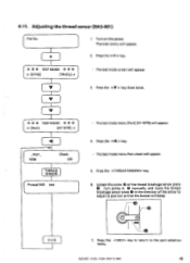
The main menu will appear. 2. Turn on the power. Press the key. * * * TEST MODE * * * Adjusting the thread sensor (BAS-401) [ File No. 1. 4-11.
The main menu will appear. 2. Turn on the power. Press the key. * * * TEST MODE * * * Adjusting the thread sensor (BAS-401) [ File No. 1. 4-11.

Service Manual
Page 84
...® is centered in the center of the cross of the XY-axis home position plate O. While pressing the < 4 > key for the BAS-412A or the key for the BAS-401, 416A and BES1210AC, turn the power switch off. • Be sure to remove the presser foot. 1. Turn XY-home position plate assembly... S manually and adjust the needle tip position so that it is no end play of wire drum X 0 so that there is in its notch...
...® is centered in the center of the cross of the XY-axis home position plate O. While pressing the < 4 > key for the BAS-412A or the key for the BAS-401, 416A and BES1210AC, turn the power switch off. • Be sure to remove the presser foot. 1. Turn XY-home position plate assembly... S manually and adjust the needle tip position so that it is no end play of wire drum X 0 so that there is in its notch...

Service Manual
Page 103
Disconnect the EMERGENCY switch connector 0 from the keyboard circuit board O. Manually loosen the two screws @ in the keyboard cable 0 and remove it . Pull the upper part of the panel 0 toward yourself and detach it . 2. ■ BAS-412A 7-6. Loosen the two screws ® . BAS-401 412A 416A • BES-1210AC 96 Keyboard circuit board (1) _ft? 1 /A*slaiatrtOaO7cn0O:j°O°OOOwO0i0mOCDOOp DDe:a 61 6/ :# ® c O 1. At this time, do not pull strongly on the EMERGENCY stop switch ® cable. 3.
Disconnect the EMERGENCY switch connector 0 from the keyboard circuit board O. Manually loosen the two screws @ in the keyboard cable 0 and remove it . Pull the upper part of the panel 0 toward yourself and detach it . 2. ■ BAS-412A 7-6. Loosen the two screws ® . BAS-401 412A 416A • BES-1210AC 96 Keyboard circuit board (1) _ft? 1 /A*slaiatrtOaO7cn0O:j°O°OOOwO0i0mOCDOOp DDe:a 61 6/ :# ® c O 1. At this time, do not pull strongly on the EMERGENCY stop switch ® cable. 3.

Service Manual
Page 106
When assembling, reverse the above procedure. LCD module assembly -O 1. Remove four screws @ and the LCD module assembly ®. 99 BAS-401 .412A.416A.BES-1210AC Remove the flat cables and from the keyboard unit. 0. 2. Manually loosen the two screws in the board cable 0 and remove it from the keyboard circuit board 6. Remove two screws...
When assembling, reverse the above procedure. LCD module assembly -O 1. Remove four screws @ and the LCD module assembly ®. 99 BAS-401 .412A.416A.BES-1210AC Remove the flat cables and from the keyboard unit. 0. 2. Manually loosen the two screws in the board cable 0 and remove it from the keyboard circuit board 6. Remove two screws...

Service Manual
Page 107
Keyboard circuit board (1) C=7 C00 CIDOCC COCCI77 /// 1. Manually loosen the two screws @ in the keyboard cable 0 and remove it . • BAS-401 • 416A • BES-1210AC 7-9. NOTE At this time, do not pull strongly on the EMERGENCY stop switch fa cable. 3. Loosen the four screws @. BES-1210AC 100 Pull the upper part of the panel 0 toward yourself and detach it . 2. BAS-401 • 412A • 416A- Disconnect the EMERGENCY switch Q connector O from the keyboard circuit board O.
Keyboard circuit board (1) C=7 C00 CIDOCC COCCI77 /// 1. Manually loosen the two screws @ in the keyboard cable 0 and remove it . • BAS-401 • 416A • BES-1210AC 7-9. NOTE At this time, do not pull strongly on the EMERGENCY stop switch fa cable. 3. Loosen the four screws @. BES-1210AC 100 Pull the upper part of the panel 0 toward yourself and detach it . 2. BAS-401 • 412A • 416A- Disconnect the EMERGENCY switch Q connector O from the keyboard circuit board O.

Service Manual
Page 110
... below. 1. NOTE Be sure to drop the keyboard unit 0. 3. Then remove it . 2. Remove the connector S from the keyboard stand . X When assembling, reverse the above procedure. Manually loosen the two screws 0 in the board cable 0 and remove it from the keyboard circuit board 0. 2. LCD module assembly 1. At this time, be careful not... to connect the ground wire O. 7-11. Remove three screws and the LCD module assembly O. 7-10. When assembling, reverse the above procedure. '.OOC1r- -eTh CSJDOC) 103 BAS-401.412A 416A • BES-1210AC
... below. 1. NOTE Be sure to drop the keyboard unit 0. 3. Then remove it . 2. Remove the connector S from the keyboard stand . X When assembling, reverse the above procedure. Manually loosen the two screws 0 in the board cable 0 and remove it from the keyboard circuit board 0. 2. LCD module assembly 1. At this time, be careful not... to connect the ground wire O. 7-11. Remove three screws and the LCD module assembly O. 7-10. When assembling, reverse the above procedure. '.OOC1r- -eTh CSJDOC) 103 BAS-401.412A 416A • BES-1210AC

Service Manual
Page 129
indicates that the procedure to follow appears in the first column of action to follow , using a yes-or-no decision-making process. indicates setting-up operation. 6. BAS-401 • 412A 416A- Trouble shooting flow chart 8-1-1. indicates switch operation. Symbols 1. 2. 3. 4. 5. selects the course of "problem determination and solution table." BES-1210AC 122 8. indicates manual operation. indicates that the procedure to follow appears on the next page. 7. Troubleshooting ■ BAS-412A 8-1. indicates turning-off the power switch.
indicates that the procedure to follow appears in the first column of action to follow , using a yes-or-no decision-making process. indicates setting-up operation. 6. BAS-401 • 412A 416A- Trouble shooting flow chart 8-1-1. indicates switch operation. Symbols 1. 2. 3. 4. 5. selects the course of "problem determination and solution table." BES-1210AC 122 8. indicates manual operation. indicates that the procedure to follow appears on the next page. 7. Troubleshooting ■ BAS-412A 8-1. indicates turning-off the power switch.

Service Manual
Page 140
... procedure to follow appears on the next page. indicates setting-up operation. Symbols r indicates manual operation. 2. indicates that the procedure to follow 4. u 6. 0 7. ■ BAS-401 • BAS-416A • BES-1210AC 8-3. indicates turning-off the power switch. 133 BAS-401 • 412A - 416A • BES-1210AC appears in the first column of action to follow , using...
... procedure to follow appears on the next page. indicates setting-up operation. Symbols r indicates manual operation. 2. indicates that the procedure to follow 4. u 6. 0 7. ■ BAS-401 • BAS-416A • BES-1210AC 8-3. indicates turning-off the power switch. 133 BAS-401 • 412A - 416A • BES-1210AC appears in the first column of action to follow , using...

Service Manual
Page 151
... faulty? •Are wires of carriages X and Y off the power and contact your dealer. Set bolt 9D. 'ThreadtaktoP opeetting lent * BAS-412 - 416 Thread take -up stopped with striking upper case cover? [How to the table below . Finding cause of operation, the safety system works so...problem referring to adjust] Remove adjustment base. • BAS-401 Thread take -up, then re-tighten it in proper position manually as in middle of problen 9-1. Mechanical problem In case of needle bar clamp or stopper correct? BAS-401 412A- 416A • BES-1210AC 144 r Th rekalike• operfline...
... faulty? •Are wires of carriages X and Y off the power and contact your dealer. Set bolt 9D. 'ThreadtaktoP opeetting lent * BAS-412 - 416 Thread take -up stopped with striking upper case cover? [How to the table below . Finding cause of operation, the safety system works so...problem referring to adjust] Remove adjustment base. • BAS-401 Thread take -up, then re-tighten it in proper position manually as in middle of problen 9-1. Mechanical problem In case of needle bar clamp or stopper correct? BAS-401 412A- 416A • BES-1210AC 144 r Th rekalike• operfline...

Service Manual
Page 155
.... Insert floppy disk in this mode. PT Missed Y_ORG. If same error message is in proper position. BAS-401 • 412A 416A • BES-1210AC 148 N Bar stop ERR Missed X_ ORG. Contact your dealer. Pulley is displayed. Error messages &#...8226; BAS-412A Refer to center of data and reenter. Message when power is removed when machine runs in incorrect position or defective. • Damaged circuit board. Check file name of area manually...
.... Insert floppy disk in this mode. PT Missed Y_ORG. If same error message is in proper position. BAS-401 • 412A 416A • BES-1210AC 148 N Bar stop ERR Missed X_ ORG. Contact your dealer. Pulley is displayed. Error messages &#...8226; BAS-412A Refer to center of data and reenter. Message when power is removed when machine runs in incorrect position or defective. • Damaged circuit board. Check file name of area manually...

Service Manual
Page 158
Contact your dealer. Move carriages X to center of area manually, then turn it . If the same error message is removed when machine runs in this mode. Disk ERR. Check where data was made, then contact .... • Damaged circuit board. is not set, set memory expansion board or decrease input data. 151 BAS-401 412A 416A • BES-1210AC Too much data, or too many stitches of PCB. ■BAS-401 • 416A • BES-1210AC Refer to the previous menu. Message when power is in entry mode No File...
Contact your dealer. Move carriages X to center of area manually, then turn it . If the same error message is removed when machine runs in this mode. Disk ERR. Check where data was made, then contact .... • Damaged circuit board. is not set, set memory expansion board or decrease input data. 151 BAS-401 412A 416A • BES-1210AC Too much data, or too many stitches of PCB. ■BAS-401 • 416A • BES-1210AC Refer to the previous menu. Message when power is in entry mode No File...


