
Quick Reference Guide - English
Page 2
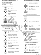
... To move BACK only to the first stitch of the option you choose END BSTART To EXIT the edit mode To return to the above display with changes in 6 # the gray box SETTING HOOP FEED POSITION HOOP FEED Press HOOP FEED to change . S R_St Co. # # N_No - Press the ...EDIT To enter EDIT mode. FO/SB - 2000/1 - 002 Co. # # N_No ERASING A STORED DESIGN FROM MEMORY Use BACK and FORWARD keys to display a "C" in effect. Press "#" to display a "J" in the gray 4 # box To move by color changes either FORWARD or BACK in design 1 Press "#" again to pick a design from ...
... To move BACK only to the first stitch of the option you choose END BSTART To EXIT the edit mode To return to the above display with changes in 6 # the gray box SETTING HOOP FEED POSITION HOOP FEED Press HOOP FEED to change . S R_St Co. # # N_No - Press the ...EDIT To enter EDIT mode. FO/SB - 2000/1 - 002 Co. # # N_No ERASING A STORED DESIGN FROM MEMORY Use BACK and FORWARD keys to display a "C" in effect. Press "#" to display a "J" in the gray 4 # box To move by color changes either FORWARD or BACK in design 1 Press "#" again to pick a design from ...
Service Manual
Page 56
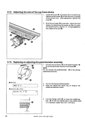
... NOTE Do not connect the potentiometer 6 to move the needle bar case 0 so that the wire is in between needle bars No.1 and No.2. 49 BAS-401 • 412A • 416A- 4-12. After adjustment, tighten the screw 0. 2. Turn the change collar @ to the sewing machine at each end...of the wire 0. 14.7N--24.7N --Brnm 4-13. Replacing an adjusting the potentiometer assembly 1. Connect the connector 6 of 1.5 - 2.5 kgf applied to display the needle bar selection screen. 0000 0 4. Loosen the screw 6, and adjust the wire tension by tightening the screws so that the slack will be 8 ...
... NOTE Do not connect the potentiometer 6 to move the needle bar case 0 so that the wire is in between needle bars No.1 and No.2. 49 BAS-401 • 412A • 416A- 4-12. After adjustment, tighten the screw 0. 2. Turn the change collar @ to the sewing machine at each end...of the wire 0. 14.7N--24.7N --Brnm 4-13. Replacing an adjusting the potentiometer assembly 1. Connect the connector 6 of 1.5 - 2.5 kgf applied to display the needle bar selection screen. 0000 0 4. Loosen the screw 6, and adjust the wire tension by tightening the screws so that the slack will be 8 ...

Service Manual
Page 57
... not move , and secure by tightening the set screws O. Check that the needle bars match the numbers in the display (No.1 to No.9) when the keys are flashing on the needle bar number display, and then turn the change collar © so that 1 and 2 are used to the neutral position turn the... this condition, insert the shaft of the potentiometer ® clockwise as far as it will go so that it does not move ). 8. BES-1210AC 50 BAS-401.412A• 416A- Shaft -- 0 5.
... not move , and secure by tightening the set screws O. Check that the needle bars match the numbers in the display (No.1 to No.9) when the keys are flashing on the needle bar number display, and then turn the change collar © so that 1 and 2 are used to the neutral position turn the... this condition, insert the shaft of the potentiometer ® clockwise as far as it will go so that it does not move ). 8. BES-1210AC 50 BAS-401.412A• 416A- Shaft -- 0 5.

Service Manual
Page 60
Also, it will appear on the display. (You learn of test mode functions 5-3-1. END * * * Test Mode * * * ® [SYNC] 0 [TRVEL] 0 [Mem.] ® [Ver. ] Press the key to return to ON (the dog shields ... the synchronize signal is used to adjust the angles of rotary encoder and stop position sensor which are set to the test mode menu. 53 BAS-401 • 412A • 416A • BES-1210AC ON/OFF indications for the machine pulley. Angles of encoder and sensor can be adjusted while checking...
Also, it will appear on the display. (You learn of test mode functions 5-3-1. END * * * Test Mode * * * ® [SYNC] 0 [TRVEL] 0 [Mem.] ® [Ver. ] Press the key to return to ON (the dog shields ... the synchronize signal is used to adjust the angles of rotary encoder and stop position sensor which are set to the test mode menu. 53 BAS-401 • 412A • 416A • BES-1210AC ON/OFF indications for the machine pulley. Angles of encoder and sensor can be adjusted while checking...

Service Manual
Page 61
... the front Ov. The hoop will be moved for length on the XY drive, and the positions of the sensor which are set on the display will be moved for the predetermined amount from the home position in order to the following keys Key Cap frame Standard cap frame Wide cap... shielded after the hoop is pressed, the hoop will be adjusted will change . (0 always appears.) Flat hoop stoppers allocated to hit the flat hoop stopers. BAS-401.412A 416A BES-1210AC 54 When either the t> or key is moved, the white circle indicating the position of the flat hoop stoppers. This...
... the front Ov. The hoop will be moved for length on the XY drive, and the positions of the sensor which are set on the display will be moved for the predetermined amount from the home position in order to the following keys Key Cap frame Standard cap frame Wide cap... shielded after the hoop is pressed, the hoop will be adjusted will change . (0 always appears.) Flat hoop stoppers allocated to hit the flat hoop stopers. BAS-401.412A 416A BES-1210AC 54 When either the t> or key is moved, the white circle indicating the position of the flat hoop stoppers. This...

Service Manual
Page 62
Memory function • This is used to the test mode menu. 55 BAS-401 - 412A - 416A ES-1210AC If the memory expansion board is selected, checking will start, and the display on the memory expansion board. Checking results [When all static RAM chips (No. 1-6) are normal] [Memory NG! Press the key. Press the...
Memory function • This is used to the test mode menu. 55 BAS-401 - 412A - 416A ES-1210AC If the memory expansion board is selected, checking will start, and the display on the memory expansion board. Checking results [When all static RAM chips (No. 1-6) are normal] [Memory NG! Press the key. Press the...
Service Manual
Page 63
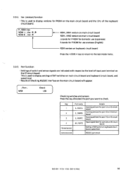
...E stands for P-ROM for port 2A on1O circuit board Setting of the keyboard circuit board. ROM J _Ver. * ,* ROM K _Ver. * j -K- This is used to display settings of DIP switches on main circuit board and keyboard circuit board, and speed level. • Results of checking RS232C interface on the main circuit... DIP switch on the 10 circuit board. Port function • Settings of input port terminal on keyboard circuit board, speed level RS232C port check BAS-401 - 412A 416A • BES-1210AC 56 P_ ROM Ver. PORTB 5_ PORTC M _ PORTS Details Input signal level for port 1A on...
...E stands for P-ROM for port 2A on1O circuit board Setting of the keyboard circuit board. ROM J _Ver. * ,* ROM K _Ver. * j -K- This is used to display settings of DIP switches on main circuit board and keyboard circuit board, and speed level. • Results of checking RS232C interface on the main circuit... DIP switch on the 10 circuit board. Port function • Settings of input port terminal on keyboard circuit board, speed level RS232C port check BAS-401 - 412A 416A • BES-1210AC 56 P_ ROM Ver. PORTB 5_ PORTC M _ PORTS Details Input signal level for port 1A on...

Service Manual
Page 64
... Either 0 or 1 is positioned above the hole in the needle plate; Press the key to return to the test mode menu. 0 Checking SPORTA This is displayed. Input port level 1 = H level 0 = L level Each time the sensor or switch setting is changed (shield or release sensor, or turn switch on ...or off), the corresponding bit number will appear when the key is always displayed. correct position.) (0 = Needle is positioned deviated from above the hole in the needle plate.) 1 is pressed. Needle bar case position ROT signal...
... Either 0 or 1 is positioned above the hole in the needle plate; Press the key to return to the test mode menu. 0 Checking SPORTA This is displayed. Input port level 1 = H level 0 = L level Each time the sensor or switch setting is changed (shield or release sensor, or turn switch on ...or off), the corresponding bit number will appear when the key is always displayed. correct position.) (0 = Needle is positioned deviated from above the hole in the needle plate.) 1 is pressed. Needle bar case position ROT signal...

Service Manual
Page 65
...sensor (1 = shielded, 0 = released) Cap frame sensor X (1 = shielded, 0 = released) Stop position sensor (1= shielded, 0 = released) Timing pulse (Either 1 or 0 is displayed every pulse.) Synchronize signal (1= ON, 0 = OFF) 3 Checking SPORTC This is used to check the following : • X- correct position.) (0 = Needle is positioned deviated from above ...Y-home position sensors • Overtravel sensors for cap frame • Rotary encoder and stop switch (1 = ON, 0= OFF) BAS-401 • 412A • 416A • BES-1210AC 58 Z Checking SPORTB This is used to check the following :...
...sensor (1 = shielded, 0 = released) Cap frame sensor X (1 = shielded, 0 = released) Stop position sensor (1= shielded, 0 = released) Timing pulse (Either 1 or 0 is displayed every pulse.) Synchronize signal (1= ON, 0 = OFF) 3 Checking SPORTC This is used to check the following : • X- correct position.) (0 = Needle is positioned deviated from above ...Y-home position sensors • Overtravel sensors for cap frame • Rotary encoder and stop switch (1 = ON, 0= OFF) BAS-401 • 412A • 416A • BES-1210AC 58 Z Checking SPORTB This is used to check the following :...
Service Manual
Page 66
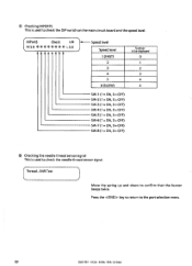
S 59 BAS-401 • 412A - 416A - Thread _SNR Test Move the spring up and down to the port selection menu. Press the key to return to confirm that the buzzer beeps twice. BES-1210AC MPortS Check MSB ******** V* LSB Speed level Speed level 1 (FAST) 2 3 4 5 6 (SLOW) Number to be displayed 0 1 2 3 4 5 SW-1 (1 = ON, 0 = OFF) SW-2 (1 = ON...
S 59 BAS-401 • 412A - 416A - Thread _SNR Test Move the spring up and down to the port selection menu. Press the key to return to confirm that the buzzer beeps twice. BES-1210AC MPortS Check MSB ******** V* LSB Speed level Speed level 1 (FAST) 2 3 4 5 6 (SLOW) Number to be displayed 0 1 2 3 4 5 SW-1 (1 = ON, 0 = OFF) SW-2 (1 = ON...

Service Manual
Page 67
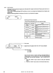
Press the key. BAS-401 412A 416A • BES-1210AC 60 6) Checking the RS232C port • Numbers 1, 2, 4, and 8 of the ASCII are sent from the sending port of the ... is not attached, the check program may not work correctly. Press the key to return to the port selection menu. Checking will start and the display below will appear sequentially. Checking result OK: normal NG: abnormal Received data will appear sequentially. 3. Port MSB Check LSB COMMUNICATION [232C S = R= * * { END...
Press the key. BAS-401 412A 416A • BES-1210AC 60 6) Checking the RS232C port • Numbers 1, 2, 4, and 8 of the ASCII are sent from the sending port of the ... is not attached, the check program may not work correctly. Press the key to return to the port selection menu. Checking will start and the display below will appear sequentially. Checking result OK: normal NG: abnormal Received data will appear sequentially. 3. Port MSB Check LSB COMMUNICATION [232C S = R= * * { END...

Service Manual
Page 71
Sync. (synchronize) function This is used to ON. 5-6. Also, it will appear on the display. (You learn of test mode functions 5-6-1. Turn the pulley. Angles of rotary encoder and stop position sensor...rotary encoder and stop position signal is set to the test mode menu. 1. * * * Test Mode * * * (-- [SYNC] [TRVEL] --o 2 BAS-401 •412A • 416A • BES-1210AC 64 END 2. Press the key to return to ON (the dog shields the sensor). ON/OFF indications... adjust the angles of encoder and sensor can be adjusted while checking signal conditions on the display.
Sync. (synchronize) function This is used to ON. 5-6. Also, it will appear on the display. (You learn of test mode functions 5-6-1. Turn the pulley. Angles of rotary encoder and stop position sensor...rotary encoder and stop position signal is set to the test mode menu. 1. * * * Test Mode * * * (-- [SYNC] [TRVEL] --o 2 BAS-401 •412A • 416A • BES-1210AC 64 END 2. Press the key to return to ON (the dog shields the sensor). ON/OFF indications... adjust the angles of encoder and sensor can be adjusted while checking signal conditions on the display.

Service Manual
Page 72
... A +Y limit 197.5 mm Where the carriage hits right and left stoppers on the rear Where there is pressed, the hoop will be moved, and the display on the left will be moved for the predetermined amount from the home position in 0.1 mm increments, and the value for length on the XY... 182.1 mm Press the or key. This function is moved, the white circle indicating the position of the sensor which are set on the display will change . 65 BAS-401 412A- 416A- Press the or key. Press the or < Po.> key. SNR Length = 077.1 mm 2. If the sensor is shielded after the...
... A +Y limit 197.5 mm Where the carriage hits right and left stoppers on the rear Where there is pressed, the hoop will be moved, and the display on the left will be moved for the predetermined amount from the home position in 0.1 mm increments, and the value for length on the XY... 182.1 mm Press the or key. This function is moved, the white circle indicating the position of the sensor which are set on the display will change . 65 BAS-401 412A- 416A- Press the or key. Press the or < Po.> key. SNR Length = 077.1 mm 2. If the sensor is shielded after the...

Service Manual
Page 73
Press the key. This is used to the home position, and the initial menu will be indicated at the specified position. 4. BAS-401 • 412A • 416A • BES-1210AC 66 Ov. The hoop will appear. Checking Memory Memory Complete! F- Memory function - As soon as this function .... Sensor =O Length '.. = 077.1 mm ..) Adjust the positions of sensor and dog so that the white circle is pressed again, the hoop will start, and the display on the memory expansion board. When the key is changed to the test mode menu.
Press the key. This is used to the home position, and the initial menu will be indicated at the specified position. 4. BAS-401 • 412A • 416A • BES-1210AC 66 Ov. The hoop will appear. Checking Memory Memory Complete! F- Memory function - As soon as this function .... Sensor =O Length '.. = 077.1 mm ..) Adjust the positions of sensor and dog so that the white circle is pressed again, the hoop will start, and the display on the memory expansion board. When the key is changed to the test mode menu.

Service Manual
Page 74
...version on the main circuit board and the CPU of the keyboard circuit board. Sets picker solenoid on each to the test mode menu. 67 BAS-401 - 412A 416A BES-1210AC Sets jump solenoid on each machine head. (Invalid when it is already raised.) Lowers presser foot on each. ...1 to 6) to check each solenoid operation. Lifts presser foot on each to the test mode menu. 5-6-5. Ver. (version) function • This is used to display versions for PROM on main circuit board J stands for P-ROM for domestic use (Japanese) E stands for P-ROM for use overseas (English) Press the key to...
...version on the main circuit board and the CPU of the keyboard circuit board. Sets picker solenoid on each to the test mode menu. 67 BAS-401 - 412A 416A BES-1210AC Sets jump solenoid on each machine head. (Invalid when it is already raised.) Lowers presser foot on each. ...1 to 6) to check each solenoid operation. Lifts presser foot on each to the test mode menu. 5-6-5. Ver. (version) function • This is used to display versions for PROM on main circuit board J stands for P-ROM for domestic use (Japanese) E stands for P-ROM for use overseas (English) Press the key to...
Service Manual
Page 76
... level Thread sensor signal check EDIT RS232C port check 3 _ Port Check * MSB******** LSB / Port name Speed level will appear when the key is used to display settings of DIP switch on the main circuit board will alternate between 1 and 0 along with respect to check. 5-6-7. Press the key to return to the...
... level Thread sensor signal check EDIT RS232C port check 3 _ Port Check * MSB******** LSB / Port name Speed level will appear when the key is used to display settings of DIP switch on the main circuit board will alternate between 1 and 0 along with respect to check. 5-6-7. Press the key to return to the...

Service Manual
Page 77
...overtravel sensors for cap frame • Rotary encoder and stop position sensor • S _ Port_ B Check MSB ****** 1 LSB Either 0 or 1 is displayed. Needle bar case position ROT signal (1 = Needle is used to check the following : • Needle bar case position signal ROT • Cap frame...= ON) Needle up sensor (1 = OFF, 0 = ON) Timing pulse (1 and 0 are alternated between every pulse.) Needle down signal (1 = ON, 0 = OFF) BAS-401 •412A • 416A • BES-1210AC 70 0 Checking S _ PORT _ A This is positioned above the hole in the needle plate; Checking S_ PORT_ B ...
...overtravel sensors for cap frame • Rotary encoder and stop position sensor • S _ Port_ B Check MSB ****** 1 LSB Either 0 or 1 is displayed. Needle bar case position ROT signal (1 = Needle is used to check the following : • Needle bar case position signal ROT • Cap frame...= ON) Needle up sensor (1 = OFF, 0 = ON) Timing pulse (1 and 0 are alternated between every pulse.) Needle down signal (1 = ON, 0 = OFF) BAS-401 •412A • 416A • BES-1210AC 70 0 Checking S _ PORT _ A This is positioned above the hole in the needle plate; Checking S_ PORT_ B ...

Service Manual
Page 78
...-4 (1 = ON, 0 = OFF) SW-5 (1 = ON, 0 = OFF) SW-6 (1 = ON, 0 = OFF) SW-7 (1 = ON, 0 = OFF) SW-8 (1 = ON, 0 = OFF) 71 BAS-401 •412A -416A - ® Checking S_PORT_C This is near the hole in the needle plate.) I Either 0 or 1is displayed. Wiper sensor (1 = Wiper is extended, 0 = Wiper is retracted) Machine motor lock signal (1 = slide, 0= release) Fan alarm...
...-4 (1 = ON, 0 = OFF) SW-5 (1 = ON, 0 = OFF) SW-6 (1 = ON, 0 = OFF) SW-7 (1 = ON, 0 = OFF) SW-8 (1 = ON, 0 = OFF) 71 BAS-401 •412A -416A - ® Checking S_PORT_C This is near the hole in the needle plate.) I Either 0 or 1is displayed. Wiper sensor (1 = Wiper is extended, 0 = Wiper is retracted) Machine motor lock signal (1 = slide, 0= release) Fan alarm...

Service Manual
Page 79
... the needle thread sensor signal. [Thread SNR Test * For the BAS-401 • 412A • 416A and BES-1210AC The buzzer will beep when the sensor pully rotates. ® Checking K _PORT _SV This is used to display settings of DIP switches on keyboard circuit board and speed level.... BAS-401 - 412A - 416A • BES-1210AC 72 K _ Port _ SV MSB ******** Check * LSB Speed level Speed level 1 (FAST) 2 3 ...
... the needle thread sensor signal. [Thread SNR Test * For the BAS-401 • 412A • 416A and BES-1210AC The buzzer will beep when the sensor pully rotates. ® Checking K _PORT _SV This is used to display settings of DIP switches on keyboard circuit board and speed level.... BAS-401 - 412A - 416A • BES-1210AC 72 K _ Port _ SV MSB ******** Check * LSB Speed level Speed level 1 (FAST) 2 3 ...
Service Manual
Page 114
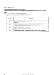
...Home position detection error occurs. • Solenoid does not operate. (Thread trimmer does not function) Needle bar case locking. Fuse No. Operation panel display is blown. Bobbin winder motor does not operate. Replacing fuse The fol lowing problems occur if the fuse is blank and the sewing machine does... not operate. 107 BAS-401 • 412A , 416A • BES-1210AC Overload • X and Y carriages do not move at all . NOTES • Be sure to use ...
...Home position detection error occurs. • Solenoid does not operate. (Thread trimmer does not function) Needle bar case locking. Fuse No. Operation panel display is blown. Bobbin winder motor does not operate. Replacing fuse The fol lowing problems occur if the fuse is blank and the sewing machine does... not operate. 107 BAS-401 • 412A , 416A • BES-1210AC Overload • X and Y carriages do not move at all . NOTES • Be sure to use ...

