
Tubular to Cap - English
Page 1
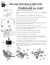
... lever. 8) Install the metal bar with the two shorter black thumbscrews (E). 12) Swing the "L" shaped plate (H) up behind the pantograph. 13) Attach the two screws (K). Other screws can cause mechanical problems. 14) Tighten the phillips or thumb screw (J) located on it, and secure with the "L"...needle plate (A-1) and replace with the cap needle plate (A-2). 3) Turn the machine off and move the switch (L) to "CAP" mode and turn the power back on. 4) Move the needle case to needle #1 using cap drive system, also please use the proper screws. BAS-416, BAS-416A & BES-1210 For Technical ...
... lever. 8) Install the metal bar with the two shorter black thumbscrews (E). 12) Swing the "L" shaped plate (H) up behind the pantograph. 13) Attach the two screws (K). Other screws can cause mechanical problems. 14) Tighten the phillips or thumb screw (J) located on it, and secure with the "L"...needle plate (A-1) and replace with the cap needle plate (A-2). 3) Turn the machine off and move the switch (L) to "CAP" mode and turn the power back on. 4) Move the needle case to needle #1 using cap drive system, also please use the proper screws. BAS-416, BAS-416A & BES-1210 For Technical ...

Cap to Tubular - English
Page 1
... machine off and move the switch (L) to "FLAT" mode and turn the power back on each side NOTE: Do not attach these two screws (K) when not using cap drive system 2) Loosen the black thumb screw (G) and slide the guide bar (F) out of the lower arm. 3) Remove ... the cap needle plate (A-2) and replace with lever. 11) Place the TUBULAR arm attachment (A) onto the machine over the positioning pins (C). 12) Attach using the needle select button. 8) Turn the pulley in the ON position. 1) Remove the two screws (K) and loosen screw (J), it may be a thumbscrew or Phillips screw. BAS-416, BAS-416A...
... machine off and move the switch (L) to "FLAT" mode and turn the power back on each side NOTE: Do not attach these two screws (K) when not using cap drive system 2) Loosen the black thumb screw (G) and slide the guide bar (F) out of the lower arm. 3) Remove ... the cap needle plate (A-2) and replace with lever. 11) Place the TUBULAR arm attachment (A) onto the machine over the positioning pins (C). 12) Attach using the needle select button. 8) Turn the pulley in the ON position. 1) Remove the two screws (K) and loosen screw (J), it may be a thumbscrew or Phillips screw. BAS-416, BAS-416A...

Parts Manual - English
Page 57
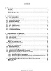
a. 1IMAEN11,* / Attachment set / Anbausatz /Jeu d'accessoires/Juego de fijaciOn REF.NO. CODE Q'TY ei.S-1 < A igt aged COMMON PARTS> 1-1 536465001 1 Z:=7:1/77714 7/Q1H 1-1-1 532844001 1 )1! Er - /.. 1-1-2 532862000 1 V =7 -1L•t 1:4X8 1-1-38 536462001 1 7-14/ I.:tr./9'1Z 1-2-1 532879001 2 i
a. 1IMAEN11,* / Attachment set / Anbausatz /Jeu d'accessoires/Juego de fijaciOn REF.NO. CODE Q'TY ei.S-1 < A igt aged COMMON PARTS> 1-1 536465001 1 Z:=7:1/77714 7/Q1H 1-1-1 532844001 1 )1! Er - /.. 1-1-2 532862000 1 V =7 -1L•t 1:4X8 1-1-38 536462001 1 7-14/ I.:tr./9'1Z 1-2-1 532879001 2 i

Parts Manual - English
Page 59
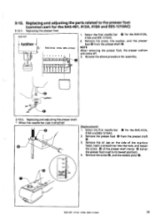
a . / Attachment set / Anbausatz / Jeu d'accessoires /Juego de fijacion REF.NO. CODE QTY e NAME OF PARTS RM 1-2-20 533888001 2 HINGE 1-2-21 062400616 4 y-Nmm4X6 SCREW, PAN M4X6 1-2-22 002400514 2 +/-^
a . / Attachment set / Anbausatz / Jeu d'accessoires /Juego de fijacion REF.NO. CODE QTY e NAME OF PARTS RM 1-2-20 533888001 2 HINGE 1-2-21 062400616 4 y-Nmm4X6 SCREW, PAN M4X6 1-2-22 002400514 2 +/-^
Service Manual
Page 3
...26 3-10-3. Thread trimmer mechanism 6 2-4. Drive, (X) feed mechanism 10 2-8. Attaching Y wire 17 3-4. Replacing and adjusting the parts related to the presser foot 26 3-10-1. Picker mechanism 9 2-7. Cap frame device (optional) 13 3. Drive, (Y) feed mechanism 11 2-9. Replacing ...18 ■ BAS-401 18 ■ BAS-412A • 416A • BES-1210AC 19 3-5. Replacing and adjusting the jump solenoid 24 3-9. Attaching X wire 16 3-3. Needle bar flip-up mechanism 8 2-6. Part names ■ BAS-401 1 ■ BAS-412A 2 ■ BAS-416A •...
...26 3-10-3. Thread trimmer mechanism 6 2-4. Drive, (X) feed mechanism 10 2-8. Attaching Y wire 17 3-4. Replacing and adjusting the parts related to the presser foot 26 3-10-1. Picker mechanism 9 2-7. Cap frame device (optional) 13 3. Drive, (Y) feed mechanism 11 2-9. Replacing ...18 ■ BAS-401 18 ■ BAS-412A • 416A • BES-1210AC 19 3-5. Replacing and adjusting the jump solenoid 24 3-9. Attaching X wire 16 3-3. Needle bar flip-up mechanism 8 2-6. Part names ■ BAS-401 1 ■ BAS-412A 2 ■ BAS-416A •...
Service Manual
Page 33
...1210AC 26 D ern erJ ern ern ern cushion L- 3-10-2. Replacing the presser foot BAS-401 ® brother 1. Remove the presser foot 0 from the presser shaft ® . 3-10. Select the first needle bar 0 for the BAS-401, 412A, 416A and BES-1210AC) 3-10-1. Replacing and adjusting the presser shaft..., 416A and BES-1210AC. 2. Remove the oil cap on the side of the machine head, insert a screwdriver into the hole, and loosen the screw 0 of the presser shaft clamp O (when the presser foot is attached U • IlD•• [Replacement] 1. Replacing and adjusting the parts ...
...1210AC 26 D ern erJ ern ern ern cushion L- 3-10-2. Replacing the presser foot BAS-401 ® brother 1. Remove the presser foot 0 from the presser shaft ® . 3-10. Select the first needle bar 0 for the BAS-401, 412A, 416A and BES-1210AC) 3-10-1. Replacing and adjusting the presser shaft..., 416A and BES-1210AC. 2. Remove the oil cap on the side of the machine head, insert a screwdriver into the hole, and loosen the screw 0 of the presser shaft clamp O (when the presser foot is attached U • IlD•• [Replacement] 1. Replacing and adjusting the parts ...

Service Manual
Page 34
...of the presser foot. 27 BAS-401 • 4124 • 416A- O ring • Be sure to insert the O ring between the presser shaft clamp 0 and the presser 0 operating base 0 before attaching the presser shaft @. © When attaching the presser guide plate, ...apply adhesive to its lowest position. 2. a Attach the presser operating base 0 with the oil cap. 5. screws_ 5. Be careful. 8. Make sure that the distance from...
...of the presser foot. 27 BAS-401 • 4124 • 416A- O ring • Be sure to insert the O ring between the presser shaft clamp 0 and the presser 0 operating base 0 before attaching the presser shaft @. © When attaching the presser guide plate, ...apply adhesive to its lowest position. 2. a Attach the presser operating base 0 with the oil cap. 5. screws_ 5. Be careful. 8. Make sure that the distance from...

Service Manual
Page 84
Loosen set screw 0 of wire drum X 0 so that wire drum X 0 can turn on the power. 0 0 0 7. Attach the X-limit dog cap @ so that it is in its notch faces toward the sensor ® when the X-axis home position dog interrupts the sensor 0 light. 6. The machine detects... position plate assembly S manually and adjust the needle tip position so that its hole. 5. r- 1 O 77 BAS-401. 412A • 416A • BES-1210AC While pressing the < 4 > key for the BAS-412A or the key for the BAS-401, 416A and BES1210AC, turn idly. 4. Then, tighten screw 0 firmly so that the Xlimit dog...
Loosen set screw 0 of wire drum X 0 so that wire drum X 0 can turn on the power. 0 0 0 7. Attach the X-limit dog cap @ so that it is in its notch faces toward the sensor ® when the X-axis home position dog interrupts the sensor 0 light. 6. The machine detects... position plate assembly S manually and adjust the needle tip position so that its hole. 5. r- 1 O 77 BAS-401. 412A • 416A • BES-1210AC While pressing the < 4 > key for the BAS-412A or the key for the BAS-401, 416A and BES1210AC, turn idly. 4. Then, tighten screw 0 firmly so that the Xlimit dog...

Service Manual
Page 87
.... 5-9-2. NOTE The home position plate is an optional part. Adjusting cap frame overtravel sensor (X direction) (Use Travel in the test mode). home position Plate BAS-401 412A • 416A • BES-1210AC 80 NOTE Be sure to remove the presser foot. 0 Uri Attach the home position plate (536461-001) to the carriage. Consult...
.... 5-9-2. NOTE The home position plate is an optional part. Adjusting cap frame overtravel sensor (X direction) (Use Travel in the test mode). home position Plate BAS-401 412A • 416A • BES-1210AC 80 NOTE Be sure to remove the presser foot. 0 Uri Attach the home position plate (536461-001) to the carriage. Consult...

Service Manual
Page 99
...; Do not bend circuit boards. Furthermore, if cap frame specifications have not been included, connector P10 will also be spare, and so its connector also will not be sure to treat the circuit board forcefully. BAS-401 • 412A- 416A • BES-...side. This clears the internal memory. • Connector P9 is a spare connector, and so the cable is easily damaged by pushing down the < 1 > key for the BAS-412 or the key for the main circuit board is not attached to turn off the ...it while holding down near each of the circuit board. • The part code for the BAS-401 and 416.
...; Do not bend circuit boards. Furthermore, if cap frame specifications have not been included, connector P10 will also be spare, and so its connector also will not be sure to treat the circuit board forcefully. BAS-401 • 412A- 416A • BES-...side. This clears the internal memory. • Connector P9 is a spare connector, and so the cable is easily damaged by pushing down the < 1 > key for the BAS-412 or the key for the main circuit board is not attached to turn off the ...it while holding down near each of the circuit board. • The part code for the BAS-401 and 416.


