
Thread Tensions - English
Page 1
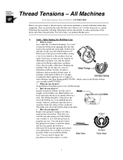
... small slotted screwdriver. Remove the spring by taking it ? Note how you check it as even as a guide. For best results, use genuine Brother parts. 1. Anti - Also called the "No Backlash Spring". It is correct. 1 I recommend the prewound, with proper tension adjustments to keep ...to spin this procedure a few times until it for? Running the machine with jumbo bobbins. Spin Spring for the correct weight), in the Brother bobbin case assembly p/n#S35584001. !" They are items related to make a difference. Try to thread tensions and tension problems as illustrated. Use...
... small slotted screwdriver. Remove the spring by taking it ? Note how you check it as even as a guide. For best results, use genuine Brother parts. 1. Anti - Also called the "No Backlash Spring". It is correct. 1 I recommend the prewound, with proper tension adjustments to keep ...to spin this procedure a few times until it for? Running the machine with jumbo bobbins. Spin Spring for the correct weight), in the Brother bobbin case assembly p/n#S35584001. !" They are items related to make a difference. Try to thread tensions and tension problems as illustrated. Use...
Thread Tensions - English
Page 2
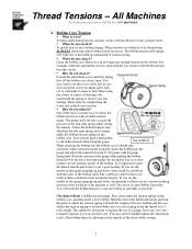
When do you adjust it should spin clockwise when viewed from the gauge. Loosen the adjustment screw until the spring lifts off bobbin as smoothly as possible. Then using the gauge. You will not need to be bent over a table just in case you see the needle on the gauge jumping up and down , the machine will take into the gauge and adjust the tension between 15-30 grams with the sides of the new bobbin and the case. Do not pull to fast or to form a proper stitch. !" If you loosen the screw too much and it 's own weight. Discard or fix that bobbin if possible. ...
When do you adjust it should spin clockwise when viewed from the gauge. Loosen the adjustment screw until the spring lifts off bobbin as smoothly as possible. Then using the gauge. You will not need to be bent over a table just in case you see the needle on the gauge jumping up and down , the machine will take into the gauge and adjust the tension between 15-30 grams with the sides of the new bobbin and the case. Do not pull to fast or to form a proper stitch. !" If you loosen the screw too much and it 's own weight. Discard or fix that bobbin if possible. ...
Thread Tensions - English
Page 3
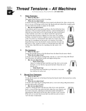
What are they for? When do you adjust them ? At installation and for ? For bobbin thread showing on the machine head. !" Pre-tensioners !" What are they for any tension problems after bobbin has been cleaned and adjusted first. How do you adjust them ? For looping problems, turn knob clockwise (tighten) no more than one full turn the knob more than two to three turns, then there may be something else that needs to be checked. 4. What are too short then loosen knob one half turn the knob more turns. o Metal Knob Type Screw the knob down until the top of ...
What are they for? When do you adjust them ? At installation and for ? For bobbin thread showing on the machine head. !" Pre-tensioners !" What are they for any tension problems after bobbin has been cleaned and adjusted first. How do you adjust them ? For looping problems, turn knob clockwise (tighten) no more than one full turn the knob more than two to three turns, then there may be something else that needs to be checked. 4. What are too short then loosen knob one half turn the knob more turns. o Metal Knob Type Screw the knob down until the top of ...
Thread Tensions - English
Page 4
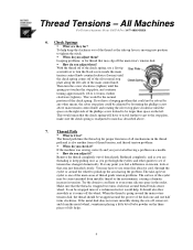
All Machines For Technical Assistance Please Call Toll Free 1-877-4BROTHER 6. When do you feel a difference in tension. Then turn the black screw inside the main tension control knob counterclockwise (loosen) until the spring just touches the stop plate, and continue turning approximately 1/8 to match as you adjust them ? If at that area just threaded closely. When the thread is going around the main rotary tension disk, the thread should also flow smoothly as the take -up lever is moving into position to see if tension has changed dramatically. Check Springs !" This...
All Machines For Technical Assistance Please Call Toll Free 1-877-4BROTHER 6. When do you feel a difference in tension. Then turn the black screw inside the main tension control knob counterclockwise (loosen) until the spring just touches the stop plate, and continue turning approximately 1/8 to match as you adjust them ? If at that area just threaded closely. When the thread is going around the main rotary tension disk, the thread should also flow smoothly as the take -up lever is moving into position to see if tension has changed dramatically. Check Springs !" This...
Thread Tensions - English
Page 5
All the above notes, suggestions, recommendations, solutions, etc. You must find that the thread is set . if the tension is thinner, you can adjust the bobbin by tightening each of them wide. When sewing hats, the lint from the top of thread around the wheel cannot grasp the wheel tight enough to change each individual top main tensioner instead by loosening it, then all the streaks will cause the bobbin streak to an exact tension you can adjust the top tensions. Sew out the bobbin tension test most of you may find the problem by doing this , look parallel, but ...
All the above notes, suggestions, recommendations, solutions, etc. You must find that the thread is set . if the tension is thinner, you can adjust the bobbin by tightening each of them wide. When sewing hats, the lint from the top of thread around the wheel cannot grasp the wheel tight enough to change each individual top main tensioner instead by loosening it, then all the streaks will cause the bobbin streak to an exact tension you can adjust the top tensions. Sew out the bobbin tension test most of you may find the problem by doing this , look parallel, but ...
Wiper Problems and Solutions - English
Page 1
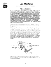
It hooks the upper thread after a trim you don't have cut the thread, then the wiper will come down to the bottom of its travel the upper thread passes to grab the upper thread and see if it and you get a wiper out error and the thread is still in the upper thread holder. If it does stick out then the needle or presser foot won't come out easily. The wiper then actually stops above the upper thread holder and the upper thread is held by the two pieces of the material into the retracted position. All Machines For Technical Assistance Please Call Toll Free 1-877-4BROTHER ...
It hooks the upper thread after a trim you don't have cut the thread, then the wiper will come down to the bottom of its travel the upper thread passes to grab the upper thread and see if it and you get a wiper out error and the thread is still in the upper thread holder. If it does stick out then the needle or presser foot won't come out easily. The wiper then actually stops above the upper thread holder and the upper thread is held by the two pieces of the material into the retracted position. All Machines For Technical Assistance Please Call Toll Free 1-877-4BROTHER ...
Wiper Problems and Solutions - English
Page 2
missing or the screw has broken off causing the solenoid sensor plate to be past the sensor. (See Wiper Assembly Parts Breakdown) • Wiper solenoid arm setscrews on the solenoid are loose or missing. (See Wiper Assembly Parts Breakdown) • Sensor needs adjustment or is no good. (See checking solenoid sensor alignment.) Wiper will not operate at all • Blown fuse on power supply circuit board. (Refer to Instruction Manual) • Wiper solenoid is defective. (See checking the wiper solenoid) • Circuit board is bad. (See checking the voltage to the wiper solenoid) Wiper ...
missing or the screw has broken off causing the solenoid sensor plate to be past the sensor. (See Wiper Assembly Parts Breakdown) • Wiper solenoid arm setscrews on the solenoid are loose or missing. (See Wiper Assembly Parts Breakdown) • Sensor needs adjustment or is no good. (See checking solenoid sensor alignment.) Wiper will not operate at all • Blown fuse on power supply circuit board. (Refer to Instruction Manual) • Wiper solenoid is defective. (See checking the wiper solenoid) • Circuit board is bad. (See checking the voltage to the wiper solenoid) Wiper ...

Wiper Problems and Solutions - English
Page 3
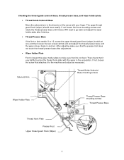
Wiper comes down and retracts but does not retract • Slot in thread guide solenoid bracket base needs to damaged the bottom of the Wiper Assembly Parts Breakdown. • Magic tapes in the shaded area of the thread guide solenoid bracket base. (See Wiper Assembly Parts Breakdown) • Bent presser foot • Wiper holder plate is either loose or missing. Apply black grease in thread presser base assembly are either missing or damaged. (See Wiper Assembly Parts Breakdown) • Thread presser base misadjusted or bent. (See checking thread presser base and cover ...
Wiper comes down and retracts but does not retract • Slot in thread guide solenoid bracket base needs to damaged the bottom of the Wiper Assembly Parts Breakdown. • Magic tapes in the shaded area of the thread guide solenoid bracket base. (See Wiper Assembly Parts Breakdown) • Bent presser foot • Wiper holder plate is either loose or missing. Apply black grease in thread presser base assembly are either missing or damaged. (See Wiper Assembly Parts Breakdown) • Thread presser base misadjusted or bent. (See checking thread presser base and cover ...

Wiper Problems and Solutions - English
Page 5
Checking the wiper solenoid Disconnect the wiper solenoid from the machine by following the cable from the solenoid and unplugging at the connector on the machine. Using a voltmeter set up correctly then either the sensor or solenoid sensor plate needs to be adjusted until the alignment is correct. Looking at the connector on the machine. Checking upper thread guide hook (wiper) alignment. Color change machine to read approximately +60VDC for about a second. Manually lower the wiper down on the machine and it will vary from machine type; The wiper should see something that go to ...
Checking the wiper solenoid Disconnect the wiper solenoid from the machine by following the cable from the solenoid and unplugging at the connector on the machine. Using a voltmeter set up correctly then either the sensor or solenoid sensor plate needs to be adjusted until the alignment is correct. Looking at the connector on the machine. Checking upper thread guide hook (wiper) alignment. Color change machine to read approximately +60VDC for about a second. Manually lower the wiper down on the machine and it will vary from machine type; The wiper should see something that go to ...
Wiper Problems and Solutions - English
Page 6
Checking the thread guide solenoid base, thread presser base, and wiper holder plate. • Thread Guide Solenoid Base Move the solenoid arm in the direction of the arrow with the wiper in the up position. After adjusting make sure that it is not bent. If not, loosen the screw that attaches it to make sure that the presser foot does not touch the thread presser base after finishing. • Thread Presser Base If the first or last needle, 9 or 12, cause the upper thread guard hook (wiper) to stick at one end then loosen the two screws at that end and adjust the thread ...
Checking the thread guide solenoid base, thread presser base, and wiper holder plate. • Thread Guide Solenoid Base Move the solenoid arm in the direction of the arrow with the wiper in the up position. After adjusting make sure that it is not bent. If not, loosen the screw that attaches it to make sure that the presser foot does not touch the thread presser base after finishing. • Thread Presser Base If the first or last needle, 9 or 12, cause the upper thread guard hook (wiper) to stick at one end then loosen the two screws at that end and adjust the thread ...
Wiper Problems and Solutions - English
Page 7
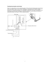
A damaged or missing lower arm cushion usually causes this. If the thread guide solenoid base is damaged or deformed it can be filed at the very bottom to be replaced as well. Checking thread guide solenoid base Check for a deformed pin on the positioning spacer, B. If the positioning spacer, B, is damaged or deformed sometimes it can be replaced. Also check the thread guide solenoid base at the bottom to remove the bump in the metal or it will need to see if it has a bump. Front View Thread Guide Solenoid Base Pin Positioning Spacer, B Washer Nut Damaged or deformed ...
A damaged or missing lower arm cushion usually causes this. If the thread guide solenoid base is damaged or deformed it can be filed at the very bottom to be replaced as well. Checking thread guide solenoid base Check for a deformed pin on the positioning spacer, B. If the positioning spacer, B, is damaged or deformed sometimes it can be replaced. Also check the thread guide solenoid base at the bottom to remove the bump in the metal or it will need to see if it has a bump. Front View Thread Guide Solenoid Base Pin Positioning Spacer, B Washer Nut Damaged or deformed ...
Knife Adjustments - English
Page 1
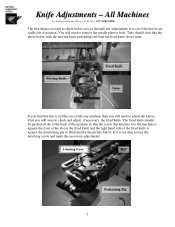
They should be pushed all the to the back of position. First you will want to check before you go through any adjustments is against the front of the slot in the fixed knife and the right hand side of the fixed knife is to see if the knives are really out of the machine so that the screw that this is not then loosen the attaching screw and make the necessary adjustments. You will need to remove the needle plate to check and adjust, if necessary, the fixed knife. If it to adjust the knives. Attaching Screw Slot Positioning Pin 1 Moving Knife Fixed Knife 1mm If ...
They should be pushed all the to the back of position. First you will want to check before you go through any adjustments is against the front of the slot in the fixed knife and the right hand side of the fixed knife is to see if the knives are really out of the machine so that the screw that this is not then loosen the attaching screw and make the necessary adjustments. You will need to remove the needle plate to check and adjust, if necessary, the fixed knife. If it to adjust the knives. Attaching Screw Slot Positioning Pin 1 Moving Knife Fixed Knife 1mm If ...
Knife Adjustments - English
Page 2
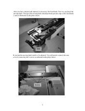
After you find the moving knife needs to remove the arm cover by the photo below . Now we can check the moving knife should protrude past the edge of the fixed knife 1 mm as illustrated by removing the 6 screws as indicated in the photo below . 1mm If you have checked and adjusted, if necessary, the fixed knife. You will need to be adjusted. Screws 2 The tip of the moving knife.
After you find the moving knife needs to remove the arm cover by the photo below . Now we can check the moving knife should protrude past the edge of the fixed knife 1 mm as illustrated by removing the 6 screws as indicated in the photo below . 1mm If you have checked and adjusted, if necessary, the fixed knife. You will need to be adjusted. Screws 2 The tip of the moving knife.
Knife Adjustments - English
Page 3
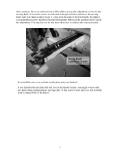
Moving Knife Adjustment Screws Re-install the arm cover and the needle plate and your adjustment screws and press the thread-trimming button on the machine and re-check the adjustment. You may have the cover removed you will be able to change both of the fixed knife. Re-tighten your finished. If that the machine will probably need to access the adjustment screws for the moving knife. If you find that doesn't work then you will still not cut the thread cleanly, you might want to achieve the correct position. Once you have to do this more than once to add two knife shims ...
Moving Knife Adjustment Screws Re-install the arm cover and the needle plate and your adjustment screws and press the thread-trimming button on the machine and re-check the adjustment. You may have the cover removed you will be able to change both of the fixed knife. Re-tighten your finished. If that the machine will probably need to access the adjustment screws for the moving knife. If you find that doesn't work then you will still not cut the thread cleanly, you might want to achieve the correct position. Once you have to do this more than once to add two knife shims ...
Maintenance Schedule - English
Page 1
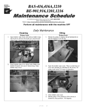
... bobbin thread is at the top. 2. Open bobbin case cover and remove bobbin case. BAS-416,416A,1210 BE-901,916,1201,1216 For Technical Assistance Please Call Toll Fre e 1-877-4BROTHER Email: tsupport@brother.com Website: http://www.brother-usa.com/industembroidery/tech_down.aspx Perform all maintenance with the machine OFF Daily Maintenance...
... bobbin thread is at the top. 2. Open bobbin case cover and remove bobbin case. BAS-416,416A,1210 BE-901,916,1201,1216 For Technical Assistance Please Call Toll Fre e 1-877-4BROTHER Email: tsupport@brother.com Website: http://www.brother-usa.com/industembroidery/tech_down.aspx Perform all maintenance with the machine OFF Daily Maintenance...
Maintenance Schedule - English
Page 2
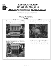
BAS-416,416A,1210 BE-901,916,1201,1216 For Technical Assistance Please Call Toll Fre e 1-877-4BROTHER Email: tsupport@brother.com Website: http://www.brother-usa.com/industembroidery/tech_down.aspx Weekly Maintenance Oiling Needle Bars 1. Remove the front plate that has the "BROTHER" logo on it by removing one or two hours of oil on...
BAS-416,416A,1210 BE-901,916,1201,1216 For Technical Assistance Please Call Toll Fre e 1-877-4BROTHER Email: tsupport@brother.com Website: http://www.brother-usa.com/industembroidery/tech_down.aspx Weekly Maintenance Oiling Needle Bars 1. Remove the front plate that has the "BROTHER" logo on it by removing one or two hours of oil on...
Maintenance Schedule - English
Page 3
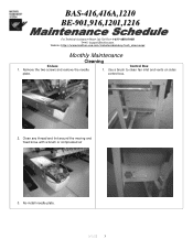
Clean any thread and lint around the moving and fixed knive with a brush or compressed air 3. BAS-416,416A,1210 BE-901,916,1201,1216 For Technical Assistance Please Call Toll Fre e 1-877-4BROTHER Email: tsupport@brother.com Website: http://www.brother-usa.com/industembroidery/tech_down.aspx Monthly Maintenance Cleaning Knives 1. Remove the two screws and remove the needle plate. Re-install needle plate. 9/1/05 3 Control Box 1. Use a brush to clean fan inlet and vents on sides control box. 2.
Clean any thread and lint around the moving and fixed knive with a brush or compressed air 3. BAS-416,416A,1210 BE-901,916,1201,1216 For Technical Assistance Please Call Toll Fre e 1-877-4BROTHER Email: tsupport@brother.com Website: http://www.brother-usa.com/industembroidery/tech_down.aspx Monthly Maintenance Cleaning Knives 1. Remove the two screws and remove the needle plate. Re-install needle plate. 9/1/05 3 Control Box 1. Use a brush to clean fan inlet and vents on sides control box. 2.
Maintenance Schedule - English
Page 4
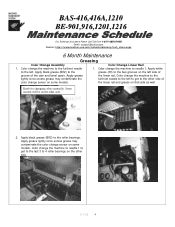
... (30) to the two grooves on some models. Knob for changing colors manually. BAS-416,416A,1210 BE-901,916,1201,1216 For Technical As sistance Please Call Toll Free 1-877-4BROTHER Email: tsupport@brother.com Website: http://www.brother-usa.com/industembroidery/tech_down.aspx 6 Month Maintenance Greasing Color Change Assembly Color Change Linear...
... (30) to the two grooves on some models. Knob for changing colors manually. BAS-416,416A,1210 BE-901,916,1201,1216 For Technical As sistance Please Call Toll Free 1-877-4BROTHER Email: tsupport@brother.com Website: http://www.brother-usa.com/industembroidery/tech_down.aspx 6 Month Maintenance Greasing Color Change Assembly Color Change Linear...
Maintenance Schedule - English
Page 5
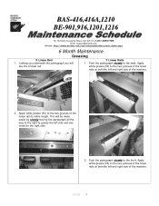
white grease (30) to the two grooves of the machine. 9/1/05 5 BAS-416,416A,1210 BE-901,916,1201,1216 For Technical Assistance Please Call Toll Fre e 1-877-4BROTHER Email: tsupport@brother.com Website: http://www.brother-usa.com/industembroidery/tech_down.aspx 6 Month Maintenance Greasing X Linear Rail Y Linear Rails 1. Apply white grease (30) to the...
white grease (30) to the two grooves of the machine. 9/1/05 5 BAS-416,416A,1210 BE-901,916,1201,1216 For Technical Assistance Please Call Toll Fre e 1-877-4BROTHER Email: tsupport@brother.com Website: http://www.brother-usa.com/industembroidery/tech_down.aspx 6 Month Maintenance Greasing X Linear Rail Y Linear Rails 1. Apply white grease (30) to the...
Maintenance Schedule - English
Page 6
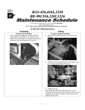
... the notch for the guide bracket and retracting lever as indicated by the arrow. 3. BAS-416,416A,1210 BE-901,916,1201,1216 For Technical Assistance Please Call Toll Fre e 1-877-4BROTHER Email: tsupport@brother.com Website: http://www.brother-usa.com/industembroidery/tech_down.aspx 6 Month Maintenance Greasing Oiling Presser Foot Assembly 1. Remove the...
... the notch for the guide bracket and retracting lever as indicated by the arrow. 3. BAS-416,416A,1210 BE-901,916,1201,1216 For Technical Assistance Please Call Toll Fre e 1-877-4BROTHER Email: tsupport@brother.com Website: http://www.brother-usa.com/industembroidery/tech_down.aspx 6 Month Maintenance Greasing Oiling Presser Foot Assembly 1. Remove the...
