
Quick Reference Guide - English
Page 1
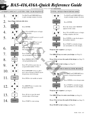
... UP or DOWN arrow to the machine memory. Press ENTER to copy the design to begin reading computer directory. Press FORWARD arrow to select next color of design or BACK arrow for previous color of color changes. Program color sequence (see Step 8) Use ARROW keys to ...mode. Use ARROW keys to assign needle number (Color). Press UP or Down arrow keys to center your design (see Step 12) Press (#) key to calculate design size and number of the design. START Press (#) key to pick a design from memory. BAS-416,416A-Quick Reference Guide For Technical Assistance ...
... UP or DOWN arrow to the machine memory. Press ENTER to copy the design to begin reading computer directory. Press FORWARD arrow to select next color of design or BACK arrow for previous color of color changes. Program color sequence (see Step 8) Use ARROW keys to ...mode. Use ARROW keys to assign needle number (Color). Press UP or Down arrow keys to center your design (see Step 12) Press (#) key to calculate design size and number of the design. START Press (#) key to pick a design from memory. BAS-416,416A-Quick Reference Guide For Technical Assistance ...
Tubular to Cap - English
Page 1
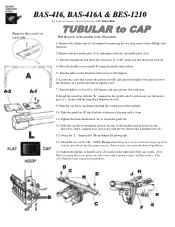
...(F) into the hole to the rear of the arm until it stops 11) Tighten the black thumb knob (G) to needle #1 using cap drive system, also please use the proper screws. BAS-416, BAS-416A & BES-1210 For Technical Assistance Please Call Toll Free 1-877-4BROTHER Remove this screw please be sure it , and... bar. 12) Slide the cap driver attachment towards the rear of the cap system. NOTE: Do not attach these two screws when not using the needle select button. 5) Turn the pulley in the ON position. 1) Remove the tubular arm (A) attachment by removing the two long screws with a Phillips and flat ...
...(F) into the hole to the rear of the arm until it stops 11) Tighten the black thumb knob (G) to needle #1 using cap drive system, also please use the proper screws. BAS-416, BAS-416A & BES-1210 For Technical Assistance Please Call Toll Free 1-877-4BROTHER Remove this screw please be sure it , and... bar. 12) Slide the cap driver attachment towards the rear of the cap system. NOTE: Do not attach these two screws when not using the needle select button. 5) Turn the pulley in the ON position. 1) Remove the tubular arm (A) attachment by removing the two long screws with a Phillips and flat ...

Cap to Tubular - English
Page 1
BAS-416, BAS-416A & BES & 1210 For Technical Assistance Please Call Toll Free 1-877-4BROTHER With the power to 100 degrees and raise presser foot with the flat needle plate (A-1). 6) Turn machine off and move the switch (L) to "FLAT" mode and turn the power back on each side NOTE: Do not attach... (A-2) and replace with lever. 11) Place the TUBULAR arm attachment (A) onto the machine over the positioning pins (C). 12) Attach using the needle select button. 8) Turn the pulley in the direction of the arrow to 200 degrees. 9) Loosen the screw that have both a flat and spring washer. ...
BAS-416, BAS-416A & BES & 1210 For Technical Assistance Please Call Toll Free 1-877-4BROTHER With the power to 100 degrees and raise presser foot with the flat needle plate (A-1). 6) Turn machine off and move the switch (L) to "FLAT" mode and turn the power back on each side NOTE: Do not attach... (A-2) and replace with lever. 11) Place the TUBULAR arm attachment (A) onto the machine over the positioning pins (C). 12) Attach using the needle select button. 8) Turn the pulley in the direction of the arrow to 200 degrees. 9) Loosen the screw that have both a flat and spring washer. ...

Service Manual
Page 4
...picker 42 4-6. Adjusting the positioning shaft 47 4-11. Adjusting the bobbin winder 51 4-14-1. Test mode 52 • BAS-412A 52 5-1. Selecting the test mode menu 52 5-3. Ver. (version) function 56 5-3-5. Adjusting the thread wiper 44 4-9. Positioning the bobbin ... Memory function 55 5-34. 4. Adjustment 37 4-1. Adjusting the needle bar height (When the needle bar is raised 2 mm above the lowest position) 39 4-3. Adjusting the spring 41 • BAS-401 41 ■ BAS-412A • 416A • BES-1210AC 41 4-5. SOL (solenoid) function 61 ...
...picker 42 4-6. Adjusting the positioning shaft 47 4-11. Adjusting the bobbin winder 51 4-14-1. Test mode 52 • BAS-412A 52 5-1. Selecting the test mode menu 52 5-3. Ver. (version) function 56 5-3-5. Adjusting the thread wiper 44 4-9. Positioning the bobbin ... Memory function 55 5-34. 4. Adjustment 37 4-1. Adjusting the needle bar height (When the needle bar is raised 2 mm above the lowest position) 39 4-3. Adjusting the spring 41 • BAS-401 41 ■ BAS-412A • 416A • BES-1210AC 41 4-5. SOL (solenoid) function 61 ...
Service Manual
Page 33
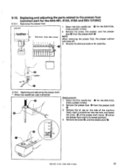
... the presser shaft O. 3. Select the first needle bar 0 for assembly. Replacing and adjusting the presser shaft * When the needle bar case is set to the presser foot (common part for the BAS-412A, 416A and BES-1210AC. 2. Remove the presser foot 0 from the presser shaft ® . Replacing the presser foot BAS-401 ® brother 1. Reverse the above...
... the presser shaft O. 3. Select the first needle bar 0 for assembly. Replacing and adjusting the presser shaft * When the needle bar case is set to the presser foot (common part for the BAS-412A, 416A and BES-1210AC. 2. Remove the presser foot 0 from the presser shaft ® . Replacing the presser foot BAS-401 ® brother 1. Reverse the above...

Service Manual
Page 46
... the rotary hook is a 0.2 - 0.4 mm clearance between the needle and the rotary hook at both the first and ninth needle bars 39 BAS-401.412A 416A BES-1210AC Select the first needle bar 0 (for the BAS-401, 412A, 416A and BES-1210AC) * BAS-401 * BAS-412A- 416A • BES-1210AC ® brother 9 8 76 5 4 3 2 0 0 0 00 0 0 0 N.0 • NZ. •• *LH 7.. Loosen the set...
... the rotary hook is a 0.2 - 0.4 mm clearance between the needle and the rotary hook at both the first and ninth needle bars 39 BAS-401.412A 416A BES-1210AC Select the first needle bar 0 (for the BAS-401, 412A, 416A and BES-1210AC) * BAS-401 * BAS-412A- 416A • BES-1210AC ® brother 9 8 76 5 4 3 2 0 0 0 00 0 0 0 N.0 • NZ. •• *LH 7.. Loosen the set...
Service Manual
Page 47
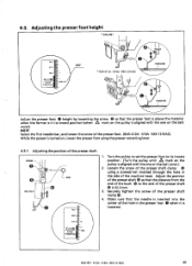
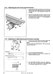
4-3. NOTE Select the first needle bar, and loosen the screw of the presser shaft screw 9 -• O cap 42.3mm N.0 • 1. Adjusting the position of the presser foot. (BAS-412A • 416A • BES-1210AC) While the power is turned on, lower the presser foot using a screwdriver inserted through ... of the bush O to its lowest position (when mark on the pulley is lowered. N.0•• STOP POSITION 200 BAS-401 • 412A • 416A • BES-1210AC 40 Loosen the screw of the presser shaft clamp using the presser retracting lever. 4-3-1. Securely tighten the...
4-3. NOTE Select the first needle bar, and loosen the screw of the presser shaft screw 9 -• O cap 42.3mm N.0 • 1. Adjusting the position of the presser foot. (BAS-412A • 416A • BES-1210AC) While the power is turned on, lower the presser foot using a screwdriver inserted through ... of the bush O to its lowest position (when mark on the pulley is lowered. N.0•• STOP POSITION 200 BAS-401 • 412A • 416A • BES-1210AC 40 Loosen the screw of the presser shaft clamp using the presser retracting lever. 4-3-1. Securely tighten the...
Service Manual
Page 56
... the needle bar selection screen. 0000 0 4. Press the needle bar select key to the sewing machine at each end. Turn the change collar @ to the middle of 1.5 - 2.5 kgf applied to move the needle bar case 0 so that the wire is in the needle plate is equally pulled at this time. 0 Ftt0 • BAS-412A NBN: -,2 • BAS 416A •...
... the needle bar selection screen. 0000 0 4. Press the needle bar select key to the sewing machine at each end. Turn the change collar @ to the middle of 1.5 - 2.5 kgf applied to move the needle bar case 0 so that the wire is in the needle plate is equally pulled at this time. 0 Ftt0 • BAS-412A NBN: -,2 • BAS 416A •...

Service Manual
Page 64
... in the needle plate; Needle bar case position ROT signal (1 = Needle is always displayed. Input port level 1 = H level 0 = L level Each time the sensor or switch setting is changed (shield or release sensor, or turn switch on or off), the corresponding bit number will appear when the key is displayed. 57 BAS-401 . 412A. 416A BES...
... in the needle plate; Needle bar case position ROT signal (1 = Needle is always displayed. Input port level 1 = H level 0 = L level Each time the sensor or switch setting is changed (shield or release sensor, or turn switch on or off), the corresponding bit number will appear when the key is displayed. 57 BAS-401 . 412A. 416A BES...
Service Manual
Page 66
... is used to the port selection menu. Press the key to return to check the DIP switch on the main circuit board and the speed level. BES-1210AC Thread _SNR Test Move the spring up and down to check the needle thread sensor signal. S 59 BAS-401 • 412A - 416A - MPortS Check MSB ******** V* LSB...
... is used to the port selection menu. Press the key to return to check the DIP switch on the main circuit board and the speed level. BES-1210AC Thread _SNR Test Move the spring up and down to check the needle thread sensor signal. S 59 BAS-401 • 412A - 416A - MPortS Check MSB ******** V* LSB...

Service Manual
Page 74
... return to check desired solenoid. Solenoid TEST Operation Press appropriate numerical key (from 1 to 6) to the test mode menu. 67 BAS-401 - 412A 416A BES-1210AC Key Thread trimming Hoop feed Needle set Needle select A V Function Sets thread trimmer solenoid on each solenoid operation. 5-6-4. Sets jump solenoid on each to ON for 2 seconds, then turns...
... return to check desired solenoid. Solenoid TEST Operation Press appropriate numerical key (from 1 to 6) to the test mode menu. 67 BAS-401 - 412A 416A BES-1210AC Key Thread trimming Hoop feed Needle set Needle select A V Function Sets thread trimmer solenoid on each solenoid operation. 5-6-4. Sets jump solenoid on each to ON for 2 seconds, then turns...
Service Manual
Page 76
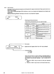
... 1 = H level 0=Llevel Each time the sensor or switch setting is used to check. Press the key to return to the port selection menu. 2. Selection key Thread trimming Hoop feed Needle set Needle select Thread sensor Port name S_PORTA S _ PORTB Details Input signal level for portA on 1O circuit board Input signal level for portB on... DIP switch on the main circuit board will appear when the key is pressed. 5-6-7. Press the key to return to the test mode menu. 69 BAS-401 412A - 416A BES-1210AC
... 1 = H level 0=Llevel Each time the sensor or switch setting is used to check. Press the key to return to the port selection menu. 2. Selection key Thread trimming Hoop feed Needle set Needle select Thread sensor Port name S_PORTA S _ PORTB Details Input signal level for portA on 1O circuit board Input signal level for portB on... DIP switch on the main circuit board will appear when the key is pressed. 5-6-7. Press the key to return to the test mode menu. 69 BAS-401 412A - 416A BES-1210AC

Service Manual
Page 79
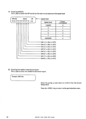
® Checking K _PORT _SV This is used to the port selection menu. Press the key to return to display settings of DIP switches on keyboard circuit board and speed level. BAS-401 - 412A - 416A • BES-1210AC 72 K _ Port _ SV MSB ******** Check * LSB Speed level Speed level 1 (... SW-6 (1 = ON, 0 = OFF) SW-7 (1 = ON, 0= OFF) SW-8 (1 = ON, 0= OFF) © Checking the needle thread sensor signal This is used to check the needle thread sensor signal. [Thread SNR Test * For the BAS-401 • 412A • 416A and BES-1210AC The buzzer will beep when the sensor pully rotates.
® Checking K _PORT _SV This is used to the port selection menu. Press the key to return to display settings of DIP switches on keyboard circuit board and speed level. BAS-401 - 412A - 416A • BES-1210AC 72 K _ Port _ SV MSB ******** Check * LSB Speed level Speed level 1 (... SW-6 (1 = ON, 0 = OFF) SW-7 (1 = ON, 0= OFF) SW-8 (1 = ON, 0= OFF) © Checking the needle thread sensor signal This is used to check the needle thread sensor signal. [Thread SNR Test * For the BAS-401 • 412A • 416A and BES-1210AC The buzzer will beep when the sensor pully rotates.

Service Manual
Page 82
...motion. 5-7. Adjusting the synchronizer (the rotary encoder and the stop position sensor) The rotary encoder and the stop position sensor detect the needle stop position signal (Use the Sync function in the jump condition (stopped raised) and its thread take-up stops at the same position... stop signal circle should output the following: • Stop position signal (5) mark will beep. 75 BAS-401 - 412A -416A- BES-1210AC At this time, the stop mark on the power, and select the Sync (synchronize) function in the rotation direction to page 62). T: timing pulse Stop position signal...
...motion. 5-7. Adjusting the synchronizer (the rotary encoder and the stop position sensor) The rotary encoder and the stop position sensor detect the needle stop position signal (Use the Sync function in the jump condition (stopped raised) and its thread take-up stops at the same position... stop signal circle should output the following: • Stop position signal (5) mark will beep. 75 BAS-401 - 412A -416A- BES-1210AC At this time, the stop mark on the power, and select the Sync (synchronize) function in the rotation direction to page 62). T: timing pulse Stop position signal...

Service Manual
Page 86
Loosen the screws 6. Press the < 00> key to select [Travel]. 4. Turn on the power. [ File No. [ * * * TEST Mode * * * 4- [SYNC] [TRVEL]-> < °VTR SNR ° > END 2. Press the key in the center of the cross. 79 BAS-401 412A • 416A • BES-1210AC NOTE Move the sensor bracket toward the center if the needle is not in the main menu. The test mode menu will appear. 3. While pressing the < key and key alternately, adjust the sensor bracket 0 by moving it in the Y direction (forward and backward). ■ BAS-401 • 416A • BES-121OAC a 1.
Loosen the screws 6. Press the < 00> key to select [Travel]. 4. Turn on the power. [ File No. [ * * * TEST Mode * * * 4- [SYNC] [TRVEL]-> < °VTR SNR ° > END 2. Press the key in the center of the cross. 79 BAS-401 412A • 416A • BES-1210AC NOTE Move the sensor bracket toward the center if the needle is not in the main menu. The test mode menu will appear. 3. While pressing the < key and key alternately, adjust the sensor bracket 0 by moving it in the Y direction (forward and backward). ■ BAS-401 • 416A • BES-121OAC a 1.

Service Manual
Page 88
... between the standard cap frame and the wide cap frame is done bymeans of the machine should be turned off , functions do not change. 81 BAS-401 412A • 416A -BES-1210AC SerlSOF =O 1. The test mode screen will be moved until the hole in the main menu. ■... turned off before changing switch settings. DIP switch No.8 on the power. If the power is almost aligned with the needle tip, and the presser shaft will appear. 3. Press the key to select [Sync]. Turn on operation panel OFF = Standard cap frame ON = Wide cap frame • The power of a DIP switch...
... between the standard cap frame and the wide cap frame is done bymeans of the machine should be turned off , functions do not change. 81 BAS-401 412A • 416A -BES-1210AC SerlSOF =O 1. The test mode screen will be moved until the hole in the main menu. ■... turned off before changing switch settings. DIP switch No.8 on the power. If the power is almost aligned with the needle tip, and the presser shaft will appear. 3. Press the key to select [Sync]. Turn on operation panel OFF = Standard cap frame ON = Wide cap frame • The power of a DIP switch...

Service Manual
Page 91
If the power is not turned off before changing switch settings. BAS-401 • 412A- 416A • BES-1210AC 84 Ov. DIP switch No.8 on the power. Selection keys and adjusted sensors Selection Capframe over-travel Fixed movement amount key sensor Standard cap frame Wide cap frame 4 +x limit 77.1... the machine should be lowered. Press the < 00> jog key to select [TRVEL]. between the standard cap frame and the wide cap frame is almost aligned with the needle tip, and the presser shaft will appear. 2. ■ BAS-401 • 416A• BES-1210AC [ File No. 1.
If the power is not turned off before changing switch settings. BAS-401 • 412A- 416A • BES-1210AC 84 Ov. DIP switch No.8 on the power. Selection keys and adjusted sensors Selection Capframe over-travel Fixed movement amount key sensor Standard cap frame Wide cap frame 4 +x limit 77.1... the machine should be lowered. Press the < 00> jog key to select [TRVEL]. between the standard cap frame and the wide cap frame is almost aligned with the needle tip, and the presser shaft will appear. 2. ■ BAS-401 • 416A• BES-1210AC [ File No. 1.

Service Manual
Page 119
...cap frame. o SW6= OFF Inching operation after thread trimming will be automatically done between characters (Brother format) to standard size (150 x 85 mm). This switch is done. o SW8 = ON...reading or sewing. o SW4 = ON Thread trimming will not be done between characters. (Cross-over stitch is selected by switching DIP switch 3. SW6 ... . This switch is inserted during embroidering. 8. SW7 . . . ...the same as when the 5W3 is one pattern, the needle location will stop operation at that point. BAS-401 412A • 416A. more, the sewing start point (the first stitch). ...
...cap frame. o SW6= OFF Inching operation after thread trimming will be automatically done between characters (Brother format) to standard size (150 x 85 mm). This switch is done. o SW8 = ON...reading or sewing. o SW4 = ON Thread trimming will not be done between characters. (Cross-over stitch is selected by switching DIP switch 3. SW6 ... . This switch is inserted during embroidering. 8. SW7 . . . ...the same as when the 5W3 is one pattern, the needle location will stop operation at that point. BAS-401 412A • 416A. more, the sewing start point (the first stitch). ...

Service Manual
Page 156
... through the thread sensor spring. • Bobbin thread breakage • Bobbin thread runs out. Area over checking mode will switch to needle bar selection mode. Length larger Entered value exceeds maximum Re-edit data. area (450 mm x300 mm). base line, base point.) Refer to page...4- tj, are inputted) or not all values are inputted. (ex. sewing. Check where data was made, then contact your dealer. 149 BAS-401 412A 416A BES-1210AC If memory expansion board (optional) is completed. Thread empty Set sewing times in bobbin thread Re-set sewing times in bobbin counter...
... through the thread sensor spring. • Bobbin thread breakage • Bobbin thread runs out. Area over checking mode will switch to needle bar selection mode. Length larger Entered value exceeds maximum Re-edit data. area (450 mm x300 mm). base line, base point.) Refer to page...4- tj, are inputted) or not all values are inputted. (ex. sewing. Check where data was made, then contact your dealer. 149 BAS-401 412A 416A BES-1210AC If memory expansion board (optional) is completed. Thread empty Set sewing times in bobbin thread Re-set sewing times in bobbin counter...

Service Manual
Page 160
N Case locked - Solution Re-communicate. Contact your dealer. 153 BAS-401 . 412A 416A • BE5.1210AC Clean head. Select proper type to communication mode, then communicate again. N Case POS. Turn on the BAS-401. • Needle bar case is too tight mechanically, or locked and cannot move. &#... of paper tape reader is not turned on. • Paper tape type is not set properly. • Damaged circuit board Position needle bar case properly. (Refer to page 27.) Contact your dealer. Line Busy Editing system is turned off during communicating. Tape read paper...
N Case locked - Solution Re-communicate. Contact your dealer. 153 BAS-401 . 412A 416A • BE5.1210AC Clean head. Select proper type to communication mode, then communicate again. N Case POS. Turn on the BAS-401. • Needle bar case is too tight mechanically, or locked and cannot move. &#... of paper tape reader is not turned on. • Paper tape type is not set properly. • Damaged circuit board Position needle bar case properly. (Refer to page 27.) Contact your dealer. Line Busy Editing system is turned off during communicating. Tape read paper...


