

Hand Book - English
Page 21
... S23833-001 1 187 Work clamp, L311- 009 S23834-001 1 188 Feed plate, 311 - 009 S23835-001 1 2000.7 BAS-311E, 311EL, 326E, 326EL 21/41 cross" For sewing the bar tack "Triangle" Ref. No. [Models BAS-311E,311EL] Part name Part code Q'ty 183 Work clamp, R311- 008 S23830-001 1 184 Work clamp, L311- 008 S23831-001 1 185...
... S23833-001 1 187 Work clamp, L311- 009 S23834-001 1 188 Feed plate, 311 - 009 S23835-001 1 2000.7 BAS-311E, 311EL, 326E, 326EL 21/41 cross" For sewing the bar tack "Triangle" Ref. No. [Models BAS-311E,311EL] Part name Part code Q'ty 183 Work clamp, R311- 008 S23830-001 1 184 Work clamp, L311- 008 S23831-001 1 185...

Hand Book - English
Page 27
No. 1 1-1 1-1-1 1-1-2 1-1-3 1-1-4 1-1-5 1-1-6 1-1-7 1-1-8 1-1-9 1-1-10 1-1-11 1-1-12 1-1-13 1-1-14 1-1-15 1-1-16 1-1-17 1-1-18 1-1-19 1-1-20 1-1-21 1-1-22 1-1-23 1-1-24 1-1-25 1-2 1-3 1-4 1-5 1-6 1-7 1-8 1-9 1-10 1-11 1-11-1 1-11-2 1-11-3 1-11-4 1-11-5 1-11-6 1-11-7 1-11-7-1 1-11-7-2 1-11-8 1-11-9 1-...Half union, Q4M5 Regulator assy Joint, 3109-4-10 Screw, pan M4 x 40 Bead band Air tube, 4L = 1300 Air tube, 4L = 300 Part name [Models BAS-311E,311EL] Part code Q'ty S44793-009 1 S12633-209 1 S12634-009 1 S12635-009 1 S12636-001 1 S12641-009 1 018681-232 2 S12638-009 1 018301...
No. 1 1-1 1-1-1 1-1-2 1-1-3 1-1-4 1-1-5 1-1-6 1-1-7 1-1-8 1-1-9 1-1-10 1-1-11 1-1-12 1-1-13 1-1-14 1-1-15 1-1-16 1-1-17 1-1-18 1-1-19 1-1-20 1-1-21 1-1-22 1-1-23 1-1-24 1-1-25 1-2 1-3 1-4 1-5 1-6 1-7 1-8 1-9 1-10 1-11 1-11-1 1-11-2 1-11-3 1-11-4 1-11-5 1-11-6 1-11-7 1-11-7-1 1-11-7-2 1-11-8 1-11-9 1-...Half union, Q4M5 Regulator assy Joint, 3109-4-10 Screw, pan M4 x 40 Bead band Air tube, 4L = 1300 Air tube, 4L = 300 Part name [Models BAS-311E,311EL] Part code Q'ty S44793-009 1 S12633-209 1 S12634-009 1 S12635-009 1 S12636-001 1 S12641-009 1 018681-232 2 S12638-009 1 018301...

Hand Book - English
Page 30
... 1 1-1 1-1-1 1-1-2 1-1-3 1-1-4 1-1-5 1-1-6 1-1-7 1-1-8 1-1-9 1-1-10 1-1-11 1-1-12 1-1-13 1-1-14 1-1-15 1-1-16 1-1-17 1-1-18 1-1-19 1-1-20 1-1-21 1-1-22 1-1-23 1-1-24 1-1-25 1-1-26 1-2 1-3 1-4 1-5 1-6 1-7 1-8 1-9 1-10 1-10 1-11 1-11-1 1-11-2 1-11-3 1-11-4 1-... Screw, pan M4 x 40 Bead band Air tube, 4L = 1300 Air tube, 4L = 300 Part name [Models BAS-326E, 326EL] Part code Q'ty S44419-009 1 S51073-009 1 S44420-009 1 S12634-009 1 S12635-009 1 S44421-...2 062404-005 2 340400-001 2 S03803-000 2 S28741-000 1 BAS-311E, 311EL, 326E, 326EL 30/41 2000.7 Inner clamping device Ref.
... 1 1-1 1-1-1 1-1-2 1-1-3 1-1-4 1-1-5 1-1-6 1-1-7 1-1-8 1-1-9 1-1-10 1-1-11 1-1-12 1-1-13 1-1-14 1-1-15 1-1-16 1-1-17 1-1-18 1-1-19 1-1-20 1-1-21 1-1-22 1-1-23 1-1-24 1-1-25 1-1-26 1-2 1-3 1-4 1-5 1-6 1-7 1-8 1-9 1-10 1-10 1-11 1-11-1 1-11-2 1-11-3 1-11-4 1-... Screw, pan M4 x 40 Bead band Air tube, 4L = 1300 Air tube, 4L = 300 Part name [Models BAS-326E, 326EL] Part code Q'ty S44419-009 1 S51073-009 1 S44420-009 1 S12634-009 1 S12635-009 1 S44421-...2 062404-005 2 340400-001 2 S03803-000 2 S28741-000 1 BAS-311E, 311EL, 326E, 326EL 30/41 2000.7 Inner clamping device Ref.
Extended Option Output Instruction Manual - English
Page 17
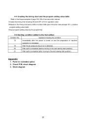
Parts for extended option 2. Block diagram 17 Appendix 1. Check PCB circuit diagram 3. 4-4 Creating the timing chart and the program setting value table Refer to the three ... operation is completed. 19 After the air pressure drop error is detected. 20 After split is completed (before moving to the next sewing start position). 21 After split is completed (after the power is turned on the timing chart and condition number table (see instruction manual page 191-), create a program setting...
Parts for extended option 2. Block diagram 17 Appendix 1. Check PCB circuit diagram 3. 4-4 Creating the timing chart and the program setting value table Refer to the three ... operation is completed. 19 After the air pressure drop error is detected. 20 After split is completed (before moving to the next sewing start position). 21 After split is completed (after the power is turned on the timing chart and condition number table (see instruction manual page 191-), create a program setting...

Network Users Manual - English
Page 95
....) Single-pedal operation by special order.) DIP switch A-7 is not used (does not rise). BAS-311E.311EL.326E.326EL 87 Cassette is carried out using an alternating clamping presser (1/4 ON, 3/4 OFF... memo-04 memo-05 Needle stops in the order Y → X and X → Y. memo-21 After the home position is finished, the work clamp rises automatically. memo-0E memo-0F Test feeding is ...are available for attaching buttons. s Memory Switches (00 - 0F) Chapter 6 Power supply and electrical parts adjustment SW No. memo-00 memo-01 When ON When moving to the start position, the &#...
....) Single-pedal operation by special order.) DIP switch A-7 is not used (does not rise). BAS-311E.311EL.326E.326EL 87 Cassette is carried out using an alternating clamping presser (1/4 ON, 3/4 OFF... memo-04 memo-05 Needle stops in the order Y → X and X → Y. memo-21 After the home position is finished, the work clamp rises automatically. memo-0E memo-0F Test feeding is ...are available for attaching buttons. s Memory Switches (00 - 0F) Chapter 6 Power supply and electrical parts adjustment SW No. memo-00 memo-01 When ON When moving to the start position, the &#...
Network Users Manual - English
Page 101
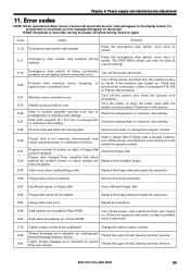
if a programmer is being continually pressed, or emergency switch connection error. E.12 E.20 E.21 E.22 E.30 E.31 E.32 Emergency stop switch was pressed during sewing. Turn off the power and check. Check the enlargement or ...Replace the floppy disk and repeat the operation. Remove the write-protection. Repeat the operation. Sewing can then resume. BAS-311E.311EL.326E.326EL 93 Chapter 6 Power supply and electrical parts adjustment 11. Machine motor operation error. No end code was pressed. E.51 Insufficient space on again. Thread breakage error...
if a programmer is being continually pressed, or emergency switch connection error. E.12 E.20 E.21 E.22 E.30 E.31 E.32 Emergency stop switch was pressed during sewing. Turn off the power and check. Check the enlargement or ...Replace the floppy disk and repeat the operation. Remove the write-protection. Repeat the operation. Sewing can then resume. BAS-311E.311EL.326E.326EL 93 Chapter 6 Power supply and electrical parts adjustment 11. Machine motor operation error. No end code was pressed. E.51 Insufficient space on again. Thread breakage error...

Network Users Manual - English
Page 112
...[E.60], the panel circuit board is defective. • Refer to #1.1-5 • Refer to #1.1-2 X pulse motor control circuit board 104 BAS-311E.311EL.326E.326EL Parts to #d1-1, -1, -3 #1 The power lamp does not light when the power is defective. Control circuit board 5. Turn on the power...error code [E.90], the power supply voltage has sharply dropped. • Check that generates strong electrical noise nearby. With error code [E.21], the machine is malfunctioning. • Check that grounding is securely made and there is no equipment that the voltage of a socket...
...[E.60], the panel circuit board is defective. • Refer to #1.1-5 • Refer to #1.1-2 X pulse motor control circuit board 104 BAS-311E.311EL.326E.326EL Parts to #d1-1, -1, -3 #1 The power lamp does not light when the power is defective. Control circuit board 5. Turn on the power...error code [E.90], the power supply voltage has sharply dropped. • Check that generates strong electrical noise nearby. With error code [E.21], the machine is malfunctioning. • Check that grounding is securely made and there is no equipment that the voltage of a socket...

Network Users Manual - English
Page 119
...PCB and connector P2 on the cord. Panel circuit board #22 Sewing is defective. 3. Programmer Panel circuit board BAS-311E.311EL.326E.326EL 111 EM switch defective. Between pins 2 and 3: ∞ Ωnormally or 0 Ω... pins 1 and 2: 0 Ω normally or ∞ Ω when the emergency stop switch is canceled. #21 The STEP BACK switch is pressed. EM switch assembly. #20 The thread trimmer does not operate after the emergency stop...• Refer to be made. 1. Check/repair/adjust Parts to #1 and #2 (panel switch). The synchronizer is pressed. 1.
...PCB and connector P2 on the cord. Panel circuit board #22 Sewing is defective. 3. Programmer Panel circuit board BAS-311E.311EL.326E.326EL 111 EM switch defective. Between pins 2 and 3: ∞ Ωnormally or 0 Ω... pins 1 and 2: 0 Ω normally or ∞ Ω when the emergency stop switch is canceled. #21 The STEP BACK switch is pressed. EM switch assembly. #20 The thread trimmer does not operate after the emergency stop...• Refer to be made. 1. Check/repair/adjust Parts to #1 and #2 (panel switch). The synchronizer is pressed. 1.
Network Users Manual - English
Page 120
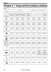
...thread guide A thread guide A S02438-001 S02438-001 S02438-001 S02439-001 S02438-001 S02438-001 S02438-001 Needle DP × 17 #21 145646-021 DP × 17 #21 145646-021 DP × 5 #16 107415-016 DP × 17 #25 145646-025 DP × 17 #19 145646-019 DP...001 Spring 104525-001 Spring 107606-001 Spring 107606-001 Spring 107606-001 Spring 104525-001 112 BAS-311E.311EL.326E.326EL Chapter 8. 1. Chapter 8. Gauge parts list according to subclasses The following parts are available for the BAS-311E, 311EL, 326E, 326EL for adding further flexibility to the range of applications.
...thread guide A thread guide A S02438-001 S02438-001 S02438-001 S02439-001 S02438-001 S02438-001 S02438-001 Needle DP × 17 #21 145646-021 DP × 17 #21 145646-021 DP × 5 #16 107415-016 DP × 17 #25 145646-025 DP × 17 #19 145646-019 DP...001 Spring 104525-001 Spring 107606-001 Spring 107606-001 Spring 107606-001 Spring 104525-001 112 BAS-311E.311EL.326E.326EL Chapter 8. 1. Chapter 8. Gauge parts list according to subclasses The following parts are available for the BAS-311E, 311EL, 326E, 326EL for adding further flexibility to the range of applications.

Network Users Manual - English
Page 132
... S43252000 S43253000 S43254000 037301015 S43255000 S43256000 S43257000 037200615 S43271000 QTY NAME OF PARTS REF.NO. Chapter 10. Option parts s Programmer 1-1 1-5 1-4 1-3 1-18 1-13 Option parts 1-9 1-15 1-13 1-7 1-8 1 2-20 1-16 1-14 1-...21 S43272000 037300615 S43267000 S43268000 S43270000 S43981000 S43259001 S43269000 S40621000 149809000 QTY NAME OF PARTS 1 MAGNET,B 6 TAPPING SCREW,PAN V M3X6 1 PROGRAMMER HARNESS 1 INVERTER HARNESS 1 CORD BUSH,KR51 2 LOWER COVER,PROGRAMMER 1 PROGRAMMER PCB ASSY 1 PROM PROGRAMMER ASSY "OPTION PARTS" 1 EMI CORE,ESD-SR-15 1 BEAD BAND,L 124 BAS-311E...
... S43252000 S43253000 S43254000 037301015 S43255000 S43256000 S43257000 037200615 S43271000 QTY NAME OF PARTS REF.NO. Chapter 10. Option parts s Programmer 1-1 1-5 1-4 1-3 1-18 1-13 Option parts 1-9 1-15 1-13 1-7 1-8 1 2-20 1-16 1-14 1-...21 S43272000 037300615 S43267000 S43268000 S43270000 S43981000 S43259001 S43269000 S40621000 149809000 QTY NAME OF PARTS 1 MAGNET,B 6 TAPPING SCREW,PAN V M3X6 1 PROGRAMMER HARNESS 1 INVERTER HARNESS 1 CORD BUSH,KR51 2 LOWER COVER,PROGRAMMER 1 PROGRAMMER PCB ASSY 1 PROM PROGRAMMER ASSY "OPTION PARTS" 1 EMI CORE,ESD-SR-15 1 BEAD BAND,L 124 BAS-311E...

Network Users Manual - English
Page 133
... WORK CLAMP FOOT 312-2 S12643001 1 OUTER WORK CLAMP,312-1 6 S10542001 1 INNER CLAMP (LL) BAS-311E.311EL.326E.326EL 125 CODE QTY NAME OF PARTS REF.NO. s Inner clamping device (Option device) 1-6 1-13 1-4 1-8 1-5 1-2 1-1-3 1-7 Chapter 10. Option parts 1-1-19 1-1-18 1-1-4 1-1-25 1-1-6 1-1-5 1-1-11 1-1-24 1-1-23 1-1-8 1-1-21 1-3 1-1-22 1-1-20 1-1-17 1-1-14 1-10 1-9 1-1-16 1-1-15 1-1-9 1-1-7 1-1-1 1-1-10 1-1-2 1-1-13 1-1-12 1-11-6 1-11...
... WORK CLAMP FOOT 312-2 S12643001 1 OUTER WORK CLAMP,312-1 6 S10542001 1 INNER CLAMP (LL) BAS-311E.311EL.326E.326EL 125 CODE QTY NAME OF PARTS REF.NO. s Inner clamping device (Option device) 1-6 1-13 1-4 1-8 1-5 1-2 1-1-3 1-7 Chapter 10. Option parts 1-1-19 1-1-18 1-1-4 1-1-25 1-1-6 1-1-5 1-1-11 1-1-24 1-1-23 1-1-8 1-1-21 1-3 1-1-22 1-1-20 1-1-17 1-1-14 1-10 1-9 1-1-16 1-1-15 1-1-9 1-1-7 1-1-1 1-1-10 1-1-2 1-1-13 1-1-12 1-11-6 1-11...

Network Users Manual - English
Page 134
... CLAMP, 326L-3 INNER CLAMP, LL WORK CLAMP BLANK, A 326L OT-FEED PLATE BLANK, H 326L t=1.2 126 BAS-311E.311EL.326E.326EL Option parts sInner clamping device (Option device) BAS-326EL 1-12 1-1-25 1-1-19 1-1-18 1-2 1-1-4 1-1-3 1-13 1-4 1-6 1-5 1-8 1-7 1-1-6 1-1-26 1-1-5 1-1-24 1-1-23 1-1-7 1-1-22 1-1-20 1-1-21 1-1-17 1-1-14 1-3 1-1-9 1-1-13 1-1-12 1-1-2 1-10 1-9 1-1-16 1-1-10 1-1-11 1-1-8 1-1-1 1-11 1 1-11-8 1-1-15 1-11-2 1-11-1 1-14 1-11...
... CLAMP, 326L-3 INNER CLAMP, LL WORK CLAMP BLANK, A 326L OT-FEED PLATE BLANK, H 326L t=1.2 126 BAS-311E.311EL.326E.326EL Option parts sInner clamping device (Option device) BAS-326EL 1-12 1-1-25 1-1-19 1-1-18 1-2 1-1-4 1-1-3 1-13 1-4 1-6 1-5 1-8 1-7 1-1-6 1-1-26 1-1-5 1-1-24 1-1-23 1-1-7 1-1-22 1-1-20 1-1-21 1-1-17 1-1-14 1-3 1-1-9 1-1-13 1-1-12 1-1-2 1-10 1-9 1-1-16 1-1-10 1-1-11 1-1-8 1-1-1 1-11 1 1-11-8 1-1-15 1-11-2 1-11-1 1-14 1-11...

Network Users Manual - English
Page 137
... 1 1 CODE S42811001 S42813001 QTY NAME OF PARTS 1 WORK CLAMP SET,S.H 1 WORK CLAMP SET,S.H 1-2 153057002 2 SCREW,BUTTON HEAD SM4.37 REF.NO. 2 2 CODE QTY NAME OF PARTS S18614001 S18621001 1 WORK CLAMP SET,AS 1 WORK CLAMP SET,AS 2 BAS-311E.311EL.326E.326EL 129 s Snap fastener and ...hook attachment device M-508K 16 M-520K 18 18 M-525K 21 21 M-533K 28 25 M-528K 12 33 OM ø7.6,ø8.6 ...
... 1 1 CODE S42811001 S42813001 QTY NAME OF PARTS 1 WORK CLAMP SET,S.H 1 WORK CLAMP SET,S.H 1-2 153057002 2 SCREW,BUTTON HEAD SM4.37 REF.NO. 2 2 CODE QTY NAME OF PARTS S18614001 S18621001 1 WORK CLAMP SET,AS 1 WORK CLAMP SET,AS 2 BAS-311E.311EL.326E.326EL 129 s Snap fastener and ...hook attachment device M-508K 16 M-520K 18 18 M-525K 21 21 M-533K 28 25 M-528K 12 33 OM ø7.6,ø8.6 ...

