
User Manual in English
Page 1
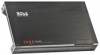
page 1 Thank you years of a PHANTOM Amplifier. USER'S MANUAL page CONTENTS 2 Introduction 2 What is included? 3 Features 3 About 2 Ohm operation 4 General precautions 4 Installation precautions 4 Mounting the amplifier 5 ...Troubleshooting 16 Specifications PHANTOM MOSFET Amplifier User's Manual - PH2.500 PH2.600 PH2.800 PH2.1000 PH2.1300 PH2.1500 Two Channel MOSFET Car Audio Amplifiers PH4.400 PH4.500 PH4.600 PH4.700 Four Channel MOSFET Car Audio Amplifiers PH1500M PH2500M MonoBlock MOSFET Car Audio Amplifiers Congratulations on your choice for car audio entertainment! It...
page 1 Thank you years of a PHANTOM Amplifier. USER'S MANUAL page CONTENTS 2 Introduction 2 What is included? 3 Features 3 About 2 Ohm operation 4 General precautions 4 Installation precautions 4 Mounting the amplifier 5 ...Troubleshooting 16 Specifications PHANTOM MOSFET Amplifier User's Manual - PH2.500 PH2.600 PH2.800 PH2.1000 PH2.1300 PH2.1500 Two Channel MOSFET Car Audio Amplifiers PH4.400 PH4.500 PH4.600 PH4.700 Four Channel MOSFET Car Audio Amplifiers PH1500M PH2500M MonoBlock MOSFET Car Audio Amplifiers Congratulations on your choice for car audio entertainment! It...
User Manual in English
Page 2
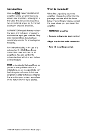
... and four 4-channel amplifiers. If something is included? You can control the subwoofer level with connector • Four (4) mounting screws PHANTOM MOSFET Amplifier User's Manual - When first unpacking your input source. What is missing, contact the store where you integrate the amp ...amplifiers are introducing eleven new amplifiers, all designed in the USA. All PHANTOM models feature variable low pass and high pass crossovers and variable input gain controls. Introduction With the PHANTOM MOSFET amplifier series, we are placed in many different kinds of installations,...
... and four 4-channel amplifiers. If something is included? You can control the subwoofer level with connector • Four (4) mounting screws PHANTOM MOSFET Amplifier User's Manual - When first unpacking your input source. What is missing, contact the store where you integrate the amp ...amplifiers are introducing eleven new amplifiers, all designed in the USA. All PHANTOM models feature variable low pass and high pass crossovers and variable input gain controls. Introduction With the PHANTOM MOSFET amplifier series, we are placed in many different kinds of installations,...
User Manual in English
Page 3
...effect. This acoustic coupling effect increases your music reproduction will also increase by about the same amount, so be distorted. PHANTOM MOSFET Amplifier User's Manual - Features Your new PHANTOM amplifier features the following: • Class A-B operation • Bridgeable outputs (except PH1500M and PH2500M) • Tri-... LED power and protection indicators • Black anodized heatsink • Remote subwoofer level control About 2 Ohm operation Your PHANTOM amplifier has been designed to operate efficiently at loads down to run the amplifiers into a 2 Ohm load. page 3
...effect. This acoustic coupling effect increases your music reproduction will also increase by about the same amount, so be distorted. PHANTOM MOSFET Amplifier User's Manual - Features Your new PHANTOM amplifier features the following: • Class A-B operation • Bridgeable outputs (except PH1500M and PH2500M) • Tri-... LED power and protection indicators • Black anodized heatsink • Remote subwoofer level control About 2 Ohm operation Your PHANTOM amplifier has been designed to operate efficiently at loads down to run the amplifiers into a 2 Ohm load. page 3
User Manual in English
Page 4
... location. 3. SHOCK HAZARD! page 4 Mounting the amplifier 1. Find a suitable location in the vehicle in damage to your audio system or your head unit or other equipment is unmounted. Confirm that supplied with all audio system components securely to become damp or wet from water or drinks. Mark the location for the mounting... or rating may result in your local dealer or service center as soon as possible . If you wish to your system, disconnect the vehicle battery. PHANTOM MOSFET Amplifier User's Manual -
... location. 3. SHOCK HAZARD! page 4 Mounting the amplifier 1. Find a suitable location in the vehicle in damage to your audio system or your head unit or other equipment is unmounted. Confirm that supplied with all audio system components securely to become damp or wet from water or drinks. Mark the location for the mounting... or rating may result in your local dealer or service center as soon as possible . If you wish to your system, disconnect the vehicle battery. PHANTOM MOSFET Amplifier User's Manual -

User Manual in English
Page 5
...gauge (or heavier) wire. 3. Connect all crossover controls/switches to the closest point on the chassis of the head unit using high-quality cables. PHANTOM MOSFET Amplifier User's Manual - Be sure you proceed. 1. Each (+) cable must have its own inline fuse. -or• Run a #4 cable...adjust the amplifier's input level control(s) to just below the level of cables from the amplifier to this distribution block and to avoid audio phase problems. 7. Connect all the connections before powering up the head unit and the amplifier. Do not mistake the input level control...
...gauge (or heavier) wire. 3. Connect all crossover controls/switches to the closest point on the chassis of the head unit using high-quality cables. PHANTOM MOSFET Amplifier User's Manual - Be sure you proceed. 1. Each (+) cable must have its own inline fuse. -or• Run a #4 cable...adjust the amplifier's input level control(s) to just below the level of cables from the amplifier to this distribution block and to avoid audio phase problems. 7. Connect all the connections before powering up the head unit and the amplifier. Do not mistake the input level control...
User Manual in English
Page 6
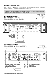
...45Hz 90Hz LOW PASS FREQUENCY PROTECTION REMOTE SUBWOOFER LEVEL CONTROL TWO C HANNE L M OSF ET POWE R AMPL IFIER To Audio Outputs of head unit or signal processor 4-Channel Amplifiers PH4.400, PH4.500, PH4.600 and PH4.700 Remote Subwoofer Level Control CH3/4 CH1/2 CH CH 4 3 CH1 CH3 HIGH LEVEL INPUTS CH CH CH2 CH4 2...min 100mV-2V 2V-8V 50Hz 45Hz high full low POWER PROTECTION FO UR C HANN EL MO SFET POWE R AMPLIFIER To FRONT Audio Outputs of head unit or signal processor To REAR Audio Outputs of head unit or signal processor PHANTOM MOSFET Amplifier User's Manual - page 6
...45Hz 90Hz LOW PASS FREQUENCY PROTECTION REMOTE SUBWOOFER LEVEL CONTROL TWO C HANNE L M OSF ET POWE R AMPL IFIER To Audio Outputs of head unit or signal processor 4-Channel Amplifiers PH4.400, PH4.500, PH4.600 and PH4.700 Remote Subwoofer Level Control CH3/4 CH1/2 CH CH 4 3 CH1 CH3 HIGH LEVEL INPUTS CH CH CH2 CH4 2...min 100mV-2V 2V-8V 50Hz 45Hz high full low POWER PROTECTION FO UR C HANN EL MO SFET POWE R AMPLIFIER To FRONT Audio Outputs of head unit or signal processor To REAR Audio Outputs of head unit or signal processor PHANTOM MOSFET Amplifier User's Manual - page 6
User Manual in English
Page 7
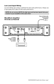
... 90Hz LOW PASS FREQUENCY PROTECTION REMOTE SUBWOOFER LEVEL CONTROL M OSF E T M ONOBL OCK POWE R AM PL I FI E R To Audio Outputs of head unit or signal processor PHANTOM MOSFET Amplifier User's Manual - Always use a high-quality RCA cable for best audio performance. Low Level Input Wiring Low-level (RCA) input wiring is preferred for best...
... 90Hz LOW PASS FREQUENCY PROTECTION REMOTE SUBWOOFER LEVEL CONTROL M OSF E T M ONOBL OCK POWE R AM PL I FI E R To Audio Outputs of head unit or signal processor PHANTOM MOSFET Amplifier User's Manual - Always use a high-quality RCA cable for best audio performance. Low Level Input Wiring Low-level (RCA) input wiring is preferred for best...
User Manual in English
Page 8
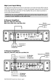
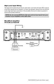
..., connect the speaker outputs from your receiver to the high level input connector of head unit PHANTOM MOSFET Amplifier User's Manual - page 8 L+ To Speaker Terminals of head unit 4-Channel Amplifiers PH4.400, PH4.500, PH4.600 and PH4.700 CH CH CH CH 4+ 4- 3- 3+ To Speaker Terminals of head unit Remote Subwoofer... MO SFET POWE R AMPLIFIER CH CH CH CH 2+ 2- 1- 1+ To Speaker Terminals of the amplifier. Be sure to observe polarity to avoid audio phase problems. NOTE: Do not connect BOTH the high level and low level inputs from the receiver to your head unit lacks RCA outputs. L-...
..., connect the speaker outputs from your receiver to the high level input connector of head unit PHANTOM MOSFET Amplifier User's Manual - page 8 L+ To Speaker Terminals of head unit 4-Channel Amplifiers PH4.400, PH4.500, PH4.600 and PH4.700 CH CH CH CH 4+ 4- 3- 3+ To Speaker Terminals of head unit Remote Subwoofer... MO SFET POWE R AMPLIFIER CH CH CH CH 2+ 2- 1- 1+ To Speaker Terminals of the amplifier. Be sure to observe polarity to avoid audio phase problems. NOTE: Do not connect BOTH the high level and low level inputs from the receiver to your head unit lacks RCA outputs. L-...
User Manual in English
Page 9
..., connect the speaker outputs from your receiver to the high level input connector of head unit Remote Subwoofer Level Control PHANTOM MOSFET Amplifier User's Manual - Be sure to observe polarity to avoid audio phase problems. NOTE: Do not connect BOTH the high level and low level inputs from the receiver to your...
..., connect the speaker outputs from your receiver to the high level input connector of head unit Remote Subwoofer Level Control PHANTOM MOSFET Amplifier User's Manual - Be sure to observe polarity to avoid audio phase problems. NOTE: Do not connect BOTH the high level and low level inputs from the receiver to your...
User Manual in English
Page 10
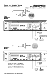
... Mode FUSES +12V GND REMOTE POWER CONNECTIONS Chassis ground point to REMOTE TURN-ON terminal of the subwoofer to the L (+) amplifier terminal. PHANTOM MOSFET Amplifier User's Manual - Subwoofer SPEAKER IMPEDANCE 4-8 OHMS L R SPEAKER CONNECTIONS BRIDGED MODE FUSES Connect the Positive (+) terminal of head unit... FUSE Battery Speaker + - Power and Speaker Wiring 2 Channel and Bridged Modes 2-Channel Amplifiers PH2.500, PH2.600, PH2.800, PH2.1000, PH2.1300, and PH2.1500 Two Channel Mode + LEFT - page 10 +12V GND REMOTE...
... Mode FUSES +12V GND REMOTE POWER CONNECTIONS Chassis ground point to REMOTE TURN-ON terminal of the subwoofer to the L (+) amplifier terminal. PHANTOM MOSFET Amplifier User's Manual - Subwoofer SPEAKER IMPEDANCE 4-8 OHMS L R SPEAKER CONNECTIONS BRIDGED MODE FUSES Connect the Positive (+) terminal of head unit... FUSE Battery Speaker + - Power and Speaker Wiring 2 Channel and Bridged Modes 2-Channel Amplifiers PH2.500, PH2.600, PH2.800, PH2.1000, PH2.1300, and PH2.1500 Two Channel Mode + LEFT - page 10 +12V GND REMOTE...
User Manual in English
Page 11
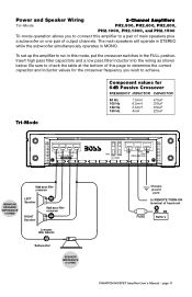
... to check the table at the bottom of this amplifier to a pair of main speakers plus a subwoofer on one pair of head unit FUSE Battery PHANTOM MOSFET Amplifier User's Manual - To set up the amplifier to run in this mode, put the crossover switches in MONO. page 11 Power and Speaker... Wiring 2-Channel Amplifiers Tri-Mode PH2.500, PH2.600, PH2.800, PH2.1000, PH2.1300, and PH2.1500 Tri-mode operation allows you to connect this page to determine the correct capacitor...
... to check the table at the bottom of this amplifier to a pair of main speakers plus a subwoofer on one pair of head unit FUSE Battery PHANTOM MOSFET Amplifier User's Manual - To set up the amplifier to run in this mode, put the crossover switches in MONO. page 11 Power and Speaker... Wiring 2-Channel Amplifiers Tri-Mode PH2.500, PH2.600, PH2.800, PH2.1000, PH2.1300, and PH2.1500 Tri-mode operation allows you to connect this page to determine the correct capacitor...

User Manual in English
Page 12
PHANTOM MOSFET Amplifier User's Manual - CH1 CH2 SPEAKER CONNECTIONS BRIDGED MODE CH3 CH4 SPEAKER CONNECTIONS BRIDGED MODE +12V GND FUSES REMOTE POWER CONNECTIONS Bridged Mode LEFT ... REMOTE TURN-ON terminal of the RIGHT subwoofer to the CH2 (-) amplifier terminal. Power and Speaker Wiring 4-Channel Amplifiers 4 Channel and Bridged Modes PH4.400, PH4.500, PH4.600 and PH4.700 CH2 Speaker CH1 Speaker Four Channel Mode SPEAKER IMPEDANCE 2-8 OHMS CH1 CH2 SPEAKER CONNECTIONS BRIDGED MODE CH3 CH4 SPEAKER CONNECTIONS BRIDGED MODE +12V...
PHANTOM MOSFET Amplifier User's Manual - CH1 CH2 SPEAKER CONNECTIONS BRIDGED MODE CH3 CH4 SPEAKER CONNECTIONS BRIDGED MODE +12V GND FUSES REMOTE POWER CONNECTIONS Bridged Mode LEFT ... REMOTE TURN-ON terminal of the RIGHT subwoofer to the CH2 (-) amplifier terminal. Power and Speaker Wiring 4-Channel Amplifiers 4 Channel and Bridged Modes PH4.400, PH4.500, PH4.600 and PH4.700 CH2 Speaker CH1 Speaker Four Channel Mode SPEAKER IMPEDANCE 2-8 OHMS CH1 CH2 SPEAKER CONNECTIONS BRIDGED MODE CH3 CH4 SPEAKER CONNECTIONS BRIDGED MODE +12V...
User Manual in English
Page 13
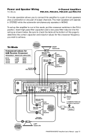
... REMOTE POWER CONNECTIONS High pass filter crossover - Power and Speaker Wiring 4-Channel Amplifiers Tri-Mode PH4.400, PH4.500, PH4.600 and PH4.700 Tri-mode operation allows you wish to achieve. CH2 Speaker + MINIMUM High pass filter crossover... SPEAKER IMPEDANCE - 4 OHMS CH1 + Speaker Low pass filter inductor LEFT Subwoofer Chassis ground point to a pair of main speakers plus a subwoofer on one pair of head unit FUSE Battery PHANTOM...
... REMOTE POWER CONNECTIONS High pass filter crossover - Power and Speaker Wiring 4-Channel Amplifiers Tri-Mode PH4.400, PH4.500, PH4.600 and PH4.700 Tri-mode operation allows you wish to achieve. CH2 Speaker + MINIMUM High pass filter crossover... SPEAKER IMPEDANCE - 4 OHMS CH1 + Speaker Low pass filter inductor LEFT Subwoofer Chassis ground point to a pair of main speakers plus a subwoofer on one pair of head unit FUSE Battery PHANTOM...
User Manual in English
Page 14
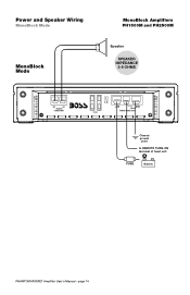
page 14 Power and Speaker Wiring MonoBlock Mode MonoBlock Amplifiers PH1500M and PH2500M MonoBlock Mode + Speaker - SPEAKER IMPEDANCE 2-8 OHMS SPEAKER CONNECTIONS FUSES +12V GND REMOTE POWER CONNECTIONS Chassis ground point to REMOTE TURN-ON terminal of head unit FUSE Battery PHANTOM MOSFET Amplifier User's Manual -
page 14 Power and Speaker Wiring MonoBlock Mode MonoBlock Amplifiers PH1500M and PH2500M MonoBlock Mode + Speaker - SPEAKER IMPEDANCE 2-8 OHMS SPEAKER CONNECTIONS FUSES +12V GND REMOTE POWER CONNECTIONS Chassis ground point to REMOTE TURN-ON terminal of head unit FUSE Battery PHANTOM MOSFET Amplifier User's Manual -
User Manual in English
Page 15
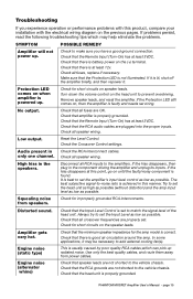
... prevent overdriving. If the Protection LED still comes on speaker leads. Amplifier gets very hot. Check that speaker leads are OK. PHANTOM MOSFET Amplifier User's Manual - Protection LED comes on until the faulty/noisy component is properly grounded. Check for short circuits on ..., compare your installation with the electrical wiring diagram on the (+) terminal. Check all RCA inputs to add external cooling fan(s). Audio present in the component driving the amplifier and unplug its inputs. Try to set the amplifier's input level control as low as...
... prevent overdriving. If the Protection LED still comes on speaker leads. Amplifier gets very hot. Check that speaker leads are OK. PHANTOM MOSFET Amplifier User's Manual - Protection LED comes on until the faulty/noisy component is properly grounded. Check for short circuits on ..., compare your installation with the electrical wiring diagram on the (+) terminal. Check all RCA inputs to add external cooling fan(s). Audio present in the component driving the amplifier and unplug its inputs. Try to set the amplifier's input level control as low as...
