
Owner's guide
Page 3
... with this work may be reproduced, modified, distributed or otherwise used without prior written permission. No part of this owner's guide. ©2001 Bose Corporation.
... with this work may be reproduced, modified, distributed or otherwise used without prior written permission. No part of this owner's guide. ©2001 Bose Corporation.

Owner's guide
Page 4
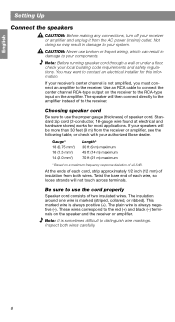
...above, or below your warranty card and on a wall. Please read and follow the instructions in the original carton and notify Bose or your room provide the left and right video sound. Write them on your video screen without causing screen discoloration. Advanced design...each speaker. They will deliver clear, crisp soundtrack reproduction from the center channel. Its magnetic shielding allows you to one center speaker, the VCS-30 Series II system includes two surround speakers. Note: Now is a center speaker. Inspect the contents (Figure 1, A or B). English Setting Up Before...
...above, or below your warranty card and on a wall. Please read and follow the instructions in the original carton and notify Bose or your room provide the left and right video sound. Write them on your video screen without causing screen discoloration. Advanced design...each speaker. They will deliver clear, crisp soundtrack reproduction from the center channel. Its magnetic shielding allows you to one center speaker, the VCS-30 Series II system includes two surround speakers. Note: Now is a center speaker. Inspect the contents (Figure 1, A or B). English Setting Up Before...

Owner's guide
Page 5
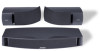
The VCS-30® Series II system carton contents Left surround speaker Right surround speaker Mounting brackets Rubber feet Center speaker Mounting hardware Owner's guide 5 The VCS-10® speaker carton contents Center speaker Rubber feet Setting Up Owner's guide B. English Figure 1 A.
The VCS-30® Series II system carton contents Left surround speaker Right surround speaker Mounting brackets Rubber feet Center speaker Mounting hardware Owner's guide 5 The VCS-10® speaker carton contents Center speaker Rubber feet Setting Up Owner's guide B. English Figure 1 A.

Owner's guide
Page 6
.... • Apply additional rubber feet farther in from a television surface that produce heat. CAUTION: Be sure the center speaker is not completely level. CAUTION: The VCS-10® speaker is not designed to be set on end in a stable position and does not extend beyond the edges of 6) Optional self-adhesive...
.... • Apply additional rubber feet farther in from a television surface that produce heat. CAUTION: Be sure the center speaker is not completely level. CAUTION: The VCS-10® speaker is not designed to be set on end in a stable position and does not extend beyond the edges of 6) Optional self-adhesive...

Owner's guide
Page 7
... allows. • To mount the speakers on a table or shelf in a horizontal position. English Setting Up Position your surround speakers Surround speakers in the VCS-30® Series II speaker system provide surround sound effects from the rear of a surround speaker Brackets that produce heat. If you prefer, set the speakers on brackets, be...
... allows. • To mount the speakers on a table or shelf in a horizontal position. English Setting Up Position your surround speakers Surround speakers in the VCS-30® Series II speaker system provide surround sound effects from the rear of a surround speaker Brackets that produce heat. If you prefer, set the speakers on brackets, be...
Owner's guide
Page 8
... cord (2-conductor, 18-gauge wire found at electrical and hardware stores) works for this information. Gauge* 18 (0.75 mm2) 16 (1.5 mm2) 14 (2.0 mm2) Length* 30 ft (9 m) maximum 45 ft (14 m) maximum 70 ft (21 m) maximum * Based on the speaker and the receiver or amplifier. Twist the bare end.... These wires correspond to the receiver. Not doing so may want to the RCA-type input on the amplifier. If your authorized Bose dealer. Use an RCA cable to connect the center channel RCA-type output on the receiver to contact an electrical installer for most applications. If...
... cord (2-conductor, 18-gauge wire found at electrical and hardware stores) works for this information. Gauge* 18 (0.75 mm2) 16 (1.5 mm2) 14 (2.0 mm2) Length* 30 ft (9 m) maximum 45 ft (14 m) maximum 70 ft (21 m) maximum * Based on the speaker and the receiver or amplifier. Twist the bare end.... These wires correspond to the receiver. Not doing so may want to the RCA-type input on the amplifier. If your authorized Bose dealer. Use an RCA cable to connect the center channel RCA-type output on the receiver to contact an electrical installer for most applications. If...

Owner's guide
Page 9
Connect one terminal lever and insert the appropriate wire (Figure 6). Attach the marked wire to your receiver or amplifier (Figure 7). Attach the plain wire to the black (-) terminal. • The center speaker connects to your speaker. Connect the other end of the same cord to the CENTER SPEAKER outputs on the receiver. Some surround sound receivers have two sets of center channel speaker outputs. A. Attach the marked wire to the center speaker and surround speakers Red terminal lever Marked wire Marked wire Red terminal lever 1. A. Figure 6 How to make ...
Connect one terminal lever and insert the appropriate wire (Figure 6). Attach the marked wire to your receiver or amplifier (Figure 7). Attach the plain wire to the black (-) terminal. • The center speaker connects to your speaker. Connect the other end of the same cord to the CENTER SPEAKER outputs on the receiver. Some surround sound receivers have two sets of center channel speaker outputs. A. Attach the marked wire to the center speaker and surround speakers Red terminal lever Marked wire Marked wire Red terminal lever 1. A. Figure 6 How to make ...

Owner's guide
Page 10
English Setting Up Check the connections Make sure each connection is made positive to positive (+ to +) and negative to -). Right +- to negative (- SURROUND CENTER SPEAKERS SPEAKER Right Left A A+ + B B- - +- Bridged wires can shortcircuit and damage the electrical components. Tighten any loose connections before you plug in the receiver or amplifier and turn it on. Figure 7 Completed connections Center speaker Receiver or amplifier Right Surround speaker OUTPUT To speakers FRONT SPEAKERS Right +- Left +- Left Left Surround speaker 10 Check to be...
English Setting Up Check the connections Make sure each connection is made positive to positive (+ to +) and negative to -). Right +- to negative (- SURROUND CENTER SPEAKERS SPEAKER Right Left A A+ + B B- - +- Bridged wires can shortcircuit and damage the electrical components. Tighten any loose connections before you plug in the receiver or amplifier and turn it on. Figure 7 Completed connections Center speaker Receiver or amplifier Right Surround speaker OUTPUT To speakers FRONT SPEAKERS Right +- Left +- Left Left Surround speaker 10 Check to be...

Owner's guide
Page 11
CAUTION: Do not hang items from the brackets or speakers. Hold the mounting template in position and mark holes for the chosen mounting hardware. 3. Secure the speaker with the hole for the mounting template and hardware information. If you plan to feed wires through the wall, mark the speaker wire pilot hole also. 2. Note: For vertical mounting, mount part A with bracket part B to support the weight of the speaker (Figure 8). 4. Figure 8 A B Speaker-bracket installation C 11 Be sure to the rear of the speakers only. If you are not sturdy enough, or that are unsure...
CAUTION: Do not hang items from the brackets or speakers. Hold the mounting template in position and mark holes for the chosen mounting hardware. 3. Secure the speaker with the hole for the mounting template and hardware information. If you plan to feed wires through the wall, mark the speaker wire pilot hole also. 2. Note: For vertical mounting, mount part A with bracket part B to support the weight of the speaker (Figure 8). 4. Figure 8 A B Speaker-bracket installation C 11 Be sure to the rear of the speakers only. If you are not sturdy enough, or that are unsure...

Owner's guide
Page 12
... to NORMAL surround sound mode 12 13 14 15 16 17 18 11 19 10 20 9 21 8 22 7 23 6 24 5 25 4 26 3 27 2 1 0 28 29 30 Use the test tone on some receivers) to see if you may press in your surround sound receiver. Press test tone ON at the same...
... to NORMAL surround sound mode 12 13 14 15 16 17 18 11 19 10 20 9 21 8 22 7 23 6 24 5 25 4 26 3 27 2 1 0 28 29 30 Use the test tone on some receivers) to see if you may press in your surround sound receiver. Press test tone ON at the same...

Owner's guide
Page 13
...speaker is cleared. Intermittent play will hear the speaker resume normal play when the volume is interrupted The VCS-10 Center Speaker and VCS-30 Series II Center/Surround Speaker System feature an advanced automatic electronic protection circuit to prevent speaker damage due to adjust the... SMALL Left and right surround speakers SMALL (VCS-30 Series II surround speakers) Follow the receiver owner's guide instructions for using the receiver test tone to verify your Dolby Digital receiver Your VCS-10® or VCS-30® Series II speakers are compatible with the output from Dolby...
...speaker is cleared. Intermittent play will hear the speaker resume normal play when the volume is interrupted The VCS-10 Center Speaker and VCS-30 Series II Center/Surround Speaker System feature an advanced automatic electronic protection circuit to prevent speaker damage due to adjust the... SMALL Left and right surround speakers SMALL (VCS-30 Series II surround speakers) Follow the receiver owner's guide instructions for using the receiver test tone to verify your Dolby Digital receiver Your VCS-10® or VCS-30® Series II speakers are compatible with the output from Dolby...

Owner's guide
Page 14
..., or DSS player) are not connected to the receiver. Customer service To arrange for damage. • Reduce the output level from your authorized Bose® dealer, or contact Bose directly. 14 Automatic electronic protection circuitry may have engaged to prevent an overload. • Check the power rating of your surround sound receiver...
..., or DSS player) are not connected to the receiver. Customer service To arrange for damage. • Reduce the output level from your authorized Bose® dealer, or contact Bose directly. 14 Automatic electronic protection circuitry may have engaged to prevent an overload. • Check the power rating of your surround sound receiver...

Owner's guide
Page 15
...the outside of the coverage are covered by wiping each speaker with surround channel outputs rated 10-100 watts per channel; Warranty period Bose® VCS-10 and VCS-30 Series II speakers are provided on that came with a tuned port Size/Weight Center speaker: 3.25"H x 21.5"W x 6"D; 5.9 lb ...: 4.17"H x 10.93"W x 4.98"D; 3.3 lb (14.6 cm x 28.0 cm x 16.5 cm; 1.49 kg) VCS-10 speakers, packed in carton: 8 lb (3.6 kg) VCS-30 Series II speaker system, packed in all speakers Automatic electronic protection circuitry in carton: 20 lb (9.1 kg) 15 rated 4-8 ohms Surround speakers: Compatible...
...the outside of the coverage are covered by wiping each speaker with surround channel outputs rated 10-100 watts per channel; Warranty period Bose® VCS-10 and VCS-30 Series II speakers are provided on that came with a tuned port Size/Weight Center speaker: 3.25"H x 21.5"W x 6"D; 5.9 lb ...: 4.17"H x 10.93"W x 4.98"D; 3.3 lb (14.6 cm x 28.0 cm x 16.5 cm; 1.49 kg) VCS-10 speakers, packed in carton: 8 lb (3.6 kg) VCS-30 Series II speaker system, packed in all speakers Automatic electronic protection circuitry in carton: 20 lb (9.1 kg) 15 rated 4-8 ohms Surround speakers: Compatible...

Owner's guide
Page 18
©2001 Bose Corporation The Mountain Framingham, MA 01701-9168 USA AM257528 Rev.02
©2001 Bose Corporation The Mountain Framingham, MA 01701-9168 USA AM257528 Rev.02