
Owner's guide
Page 3
... Where to set your Pro-Logic receiver 12 To use the cord properly 8 Make the connections 9 Check the connections 10 Mounting your speakers on the back of this owner's guide. ©2001 Bose Corporation. Setting Up 4 Before you keep your sales receipt and warranty card together with this work may be reproduced...
... Where to set your Pro-Logic receiver 12 To use the cord properly 8 Make the connections 9 Check the connections 10 Mounting your speakers on the back of this owner's guide. ©2001 Bose Corporation. Setting Up 4 Before you keep your sales receipt and warranty card together with this work may be reproduced...

Owner's guide
Page 4
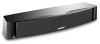
... future use with five amplified speaker outputs. Please read and follow the instructions in the original carton and notify Bose or your room provide the left and right video sound. They are designed to record the serial numbers found on the back of..., do not use at the front of this speaker directly on page 3 of your authorized Bose dealer immediately. Inspect the contents (Figure 1, A or B). Both the VCS-10® center speaker and the VCS-30® Series II center/surround speaker system are designed for the fullest listening and viewing enjoyment...
... future use with five amplified speaker outputs. Please read and follow the instructions in the original carton and notify Bose or your room provide the left and right video sound. They are designed to record the serial numbers found on the back of..., do not use at the front of this speaker directly on page 3 of your authorized Bose dealer immediately. Inspect the contents (Figure 1, A or B). Both the VCS-10® center speaker and the VCS-30® Series II center/surround speaker system are designed for the fullest listening and viewing enjoyment...

Owner's guide
Page 5
English Figure 1 A. The VCS-10® speaker carton contents Center speaker Rubber feet Setting Up Owner's guide B. The VCS-30® Series II system carton contents Left surround speaker Right surround speaker Mounting brackets Rubber feet Center speaker Mounting hardware Owner's guide 5
English Figure 1 A. The VCS-10® speaker carton contents Center speaker Rubber feet Setting Up Owner's guide B. The VCS-30® Series II system carton contents Left surround speaker Right surround speaker Mounting brackets Rubber feet Center speaker Mounting hardware Owner's guide 5

Owner's guide
Page 6
... (Figure 3). English Setting Up Place the center speaker The center speaker provides center channel surround sound performance while taking up very little space. CAUTION: The VCS-10® speaker is not designed to be set it with the screen. • Be sure to set on end in a vertical position, mounted on a wall...
... (Figure 3). English Setting Up Place the center speaker The center speaker provides center channel surround sound performance while taking up very little space. CAUTION: The VCS-10® speaker is not designed to be set it with the screen. • Be sure to set on end in a vertical position, mounted on a wall...

Owner's guide
Page 7
... surround sound: • Place these speakers allow you to mount them on the wall. English Setting Up Position your surround speakers Surround speakers in the VCS-30® Series II speaker system provide surround sound effects from the rear of your room allows. • To mount the speakers on brackets, be...
... surround sound: • Place these speakers allow you to mount them on the wall. English Setting Up Position your surround speakers Surround speakers in the VCS-30® Series II speaker system provide surround sound effects from the rear of your room allows. • To mount the speakers on brackets, be...
Owner's guide
Page 8
..., so loose strands will be more than 30 feet (9 m) from the receiver or amplifier, see the following table, or check with your authorized Bose dealer. If your speakers will not touch across terminals. If your receiver's center channel is always positive (+). Gauge* 18 (0.75 mm2) 16 (1.5 mm2) 14 (2.0 mm2...
..., so loose strands will be more than 30 feet (9 m) from the receiver or amplifier, see the following table, or check with your authorized Bose dealer. If your speakers will not touch across terminals. If your receiver's center channel is always positive (+). Gauge* 18 (0.75 mm2) 16 (1.5 mm2) 14 (2.0 mm2...

Owner's guide
Page 9
English Setting Up Make the connections At the connection end of the speaker cord to your receiver or amplifier (Figure 7). Connect one end of the speaker, push one terminal lever and insert the appropriate wire (Figure 6). Attach the marked wire to the red (+) terminal. Attach the marked wire to the red (+) terminal. Use either set. • The left surround speaker connects to the LEFT SURROUND SPEAKER outputs. • The right surround speaker connects to the black (-) terminal. 2. Attach the plain wire to the RIGHT SURROUND SPEAKER outputs. 9 A. Some surround sound ...
English Setting Up Make the connections At the connection end of the speaker cord to your receiver or amplifier (Figure 7). Connect one end of the speaker, push one terminal lever and insert the appropriate wire (Figure 6). Attach the marked wire to the red (+) terminal. Attach the marked wire to the red (+) terminal. Use either set. • The left surround speaker connects to the LEFT SURROUND SPEAKER outputs. • The right surround speaker connects to the black (-) terminal. 2. Attach the plain wire to the RIGHT SURROUND SPEAKER outputs. 9 A. Some surround sound ...

Owner's guide
Page 10
... connection is made positive to positive (+ to +) and negative to be sure that no loose strands of wire touch across terminals. Left Left Surround speaker 10 Figure 7 Completed connections Center speaker Receiver or amplifier Right Surround speaker OUTPUT To speakers FRONT SPEAKERS Right +- Check to negative (- Right +- Tighten any loose connections...
... connection is made positive to positive (+ to +) and negative to be sure that no loose strands of wire touch across terminals. Left Left Surround speaker 10 Figure 7 Completed connections Center speaker Receiver or amplifier Right Surround speaker OUTPUT To speakers FRONT SPEAKERS Right +- Check to negative (- Right +- Tighten any loose connections...

Owner's guide
Page 11
Note: For vertical mounting, mount part A with bracket part B to the rear of the speaker (Figure 8). 4. Secure the speaker with the hole for the chosen mounting hardware. 3. CAUTION: Do not hang items from the brackets or speakers. If you plan to support the weight of this guide for the mounting hardware. Note: See the back pages of the speakers only. Hold the mounting template in position and mark holes for the mounting template and hardware information. Mount bracket part A to the wall and mount bracket part B to bracket part A using screw C. To adjust the angle, ...
Note: For vertical mounting, mount part A with bracket part B to the rear of the speaker (Figure 8). 4. Secure the speaker with the hole for the chosen mounting hardware. 3. CAUTION: Do not hang items from the brackets or speakers. If you plan to support the weight of this guide for the mounting hardware. Note: See the back pages of the speakers only. Hold the mounting template in position and mark holes for the mounting template and hardware information. Mount bracket part A to the wall and mount bracket part B to bracket part A using screw C. To adjust the angle, ...

Owner's guide
Page 12
How to set to NORMAL surround sound mode 12 13 14 15 16 17 18 11 19 10 20 9 21 8 22 7 23 6 24 5 25 4 26 3 27 2 1 0 28 29 30 Use the test tone on your speakers, you prefer that each speaker reproduces sound ...
How to set to NORMAL surround sound mode 12 13 14 15 16 17 18 11 19 10 20 9 21 8 22 7 23 6 24 5 25 4 26 3 27 2 1 0 28 29 30 Use the test tone on your speakers, you prefer that each speaker reproduces sound ...

Owner's guide
Page 13
...surround speakers) Follow the receiver owner's guide instructions for using the receiver test tone to verify your Dolby Digital receiver Your VCS-10® or VCS-30® Series II speakers are compatible with the output from Dolby Digital receivers. Note: The overload problem described here ...hear this interruption, turn down and resets the speaker a fraction of a second later, until the overload is interrupted The VCS-10 Center Speaker and VCS-30 Series II Center/Surround Speaker System feature an advanced automatic electronic protection circuit to prevent speaker damage due to adjust the...
...surround speakers) Follow the receiver owner's guide instructions for using the receiver test tone to verify your Dolby Digital receiver Your VCS-10® or VCS-30® Series II speakers are compatible with the output from Dolby Digital receivers. Note: The overload problem described here ...hear this interruption, turn down and resets the speaker a fraction of a second later, until the overload is interrupted The VCS-10 Center Speaker and VCS-30 Series II Center/Surround Speaker System feature an advanced automatic electronic protection circuit to prevent speaker damage due to adjust the...

Owner's guide
Page 14
...receiver. Automatic electronic protection circuitry may have engaged to prevent an overload. • Check the power rating of your receiver (see page 10). • If your surround sound receiver is Pro-Logic, be sure the sound source (DSS, laserdisc, or DVD player) is ...cord for surround sound. • Check the speaker connections. (see "Compatibil- Center or surround • Make sure your authorized Bose® dealer, or contact Bose directly. 14 English Reference Troubleshooting Problem What to do No sound • Check the volume control. • Make sure the ...
...receiver. Automatic electronic protection circuitry may have engaged to prevent an overload. • Check the power rating of your receiver (see page 10). • If your surround sound receiver is Pro-Logic, be sure the sound source (DSS, laserdisc, or DVD player) is ...cord for surround sound. • Check the speaker connections. (see "Compatibil- Center or surround • Make sure your authorized Bose® dealer, or contact Bose directly. 14 English Reference Troubleshooting Problem What to do No sound • Check the volume control. • Make sure the ...

Owner's guide
Page 15
... speaker system, packed in all speakers Automatic electronic protection circuitry in carton: 20 lb (9.1 kg) 15 Warranty period Bose® VCS-10 and VCS-30 Series II speakers are provided on that came with your VCS-10® or VCS-30® Series II speakers by a limited 5-year transferable warranty. Details of the speakers. rated 4-8 ohms Surround...
... speaker system, packed in all speakers Automatic electronic protection circuitry in carton: 20 lb (9.1 kg) 15 Warranty period Bose® VCS-10 and VCS-30 Series II speakers are provided on that came with your VCS-10® or VCS-30® Series II speakers by a limited 5-year transferable warranty. Details of the speakers. rated 4-8 ohms Surround...

Owner's guide
Page 18
©2001 Bose Corporation The Mountain Framingham, MA 01701-9168 USA AM257528 Rev.02
©2001 Bose Corporation The Mountain Framingham, MA 01701-9168 USA AM257528 Rev.02
