Installation guide
Page 2
... meets all of used batteries properly, following any local regulations. Please read this installation guide Please take the time to rain or moisture. Save your LIFESTYLE® media center and Acoustimass® module enclosures: The lightning flash with arrowhead symbol, within an equilateral triangle, is intended to alert the user to...
... meets all of used batteries properly, following any local regulations. Please read this installation guide Please take the time to rain or moisture. Save your LIFESTYLE® media center and Acoustimass® module enclosures: The lightning flash with arrowhead symbol, within an equilateral triangle, is intended to alert the user to...

Installation guide
Page 3
...or disassembly is prohibited. System: (circle one) LIFESTYLE® 18 system LIFESTYLE® 28 system LIFESTYLE® 38 system LIFESTYLE® 48 system Media center serial number Acoustimass ... technology licensed by Macrovision Corporation and other intellectual property rights owned by Fraunhofer IIS and THOMSON multimedia. Reverse engineering or disassembly is prohibited. 3 Manufactured under license..." and "DTS Digital Surround" are trademarks of the U.S. Bose recommends that is subject to Bose. This product incorporates copyright protection technology that you keep your sales...
...or disassembly is prohibited. System: (circle one) LIFESTYLE® 18 system LIFESTYLE® 28 system LIFESTYLE® 38 system LIFESTYLE® 48 system Media center serial number Acoustimass ... technology licensed by Macrovision Corporation and other intellectual property rights owned by Fraunhofer IIS and THOMSON multimedia. Reverse engineering or disassembly is prohibited. 3 Manufactured under license..." and "DTS Digital Surround" are trademarks of the U.S. Bose recommends that is subject to Bose. This product incorporates copyright protection technology that you keep your sales...

Installation guide
Page 4
... 24 Connecting your VCR to the system 25 Connecting your cable/satellite box to the system 26 Using Component video connections 27 Connecting a game console 28 Connecting other components 29 Connecting record/playback equipment 29 Connecting other playback equipment 29 Using digital audio connections 30 Other jacks on the media center...
... 24 Connecting your VCR to the system 25 Connecting your cable/satellite box to the system 26 Using Component video connections 27 Connecting a game console 28 Connecting other components 29 Connecting record/playback equipment 29 Connecting other playback equipment 29 Using digital audio connections 30 Other jacks on the media center...
Installation guide
Page 5
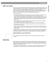
...systems or in the carton. You will identify and connect the cables that are four different systems, the LIFESTYLE® 18 Series II, LIFESTYLE® 28 Series II, LIFESTYLE® 38, and the LIFESTYLE® 48 systems. All include multiple room connections, most include the AdaptiQ® audio calibration system, and.... Refer to see the on these pages show the components of several LIFESTYLE® DVD entertainment systems. Your system will set the system up the audio portion of a Bose® LIFESTYLE® DVD home entertainment system. English Introduction Before you begin Thank you...
...systems or in the carton. You will identify and connect the cables that are four different systems, the LIFESTYLE® 18 Series II, LIFESTYLE® 28 Series II, LIFESTYLE® 38, and the LIFESTYLE® 48 systems. All include multiple room connections, most include the AdaptiQ® audio calibration system, and.... Refer to see the on these pages show the components of several LIFESTYLE® DVD entertainment systems. Your system will set the system up the audio portion of a Bose® LIFESTYLE® DVD home entertainment system. English Introduction Before you begin Thank you...
Installation guide
Page 6
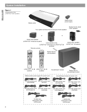
... one type of cube speaker: Rubber foot for Jewel Cube® speaker or or Single cube speaker (LIFESTYLE® 18 Series II system) Cube speaker array (LIFESTYLE® 28 Series II & LIFESTYLE® 38 systems) Remote controls Jewel Cube® speaker (LIFESTYLE® 48 system) On Off Mute All Mute CD·DVD FM·AM AUX TV Input...
... one type of cube speaker: Rubber foot for Jewel Cube® speaker or or Single cube speaker (LIFESTYLE® 18 Series II system) Cube speaker array (LIFESTYLE® 28 Series II & LIFESTYLE® 38 systems) Remote controls Jewel Cube® speaker (LIFESTYLE® 48 system) On Off Mute All Mute CD·DVD FM·AM AUX TV Input...
Installation guide
Page 7
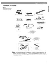
For example, if you intend to use, and your TV supports the progressive scan feature, you will need other cables and adapters to your home theater setup. English Cables and accessories Figure 2 Cables and accessories included with your system System Installation L R Front speaker cables Surround speaker cables Audio input cable Stereo audio cable S-Video cable Two component video adapters FM antenna Video cable (6 ft) Batteries AM loop antenna IR emitter cable Setup disc 1 ADAPTiQ® audio calibration system Setup disc 2 Mounting strip TV on/off sensor or SCART ...
For example, if you intend to use, and your TV supports the progressive scan feature, you will need other cables and adapters to your home theater setup. English Cables and accessories Figure 2 Cables and accessories included with your system System Installation L R Front speaker cables Surround speaker cables Audio input cable Stereo audio cable S-Video cable Two component video adapters FM antenna Video cable (6 ft) Batteries AM loop antenna IR emitter cable Setup disc 1 ADAPTiQ® audio calibration system Setup disc 2 Mounting strip TV on/off sensor or SCART ...
Installation guide
Page 8
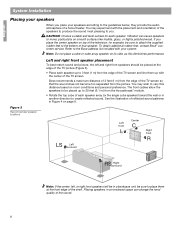
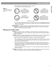
... below, they provide the audio atmosphere of the shelf. Placing speakers in Figure 4 on smooth surfaces like marble, glass, or highly polished wood. Bose recommends a maximum distance of 3 feet (1 m) from the Acoustimass® module. • Rotate the top cube of reflected sound patterns in an... the picture. English System Installation Placing your speakers When you place your system. To obtain additional rubber feet, contact Bose® customer service. CAUTION: Choose a stable and level surface for example, be placed up with your speakers according to the...
... below, they provide the audio atmosphere of the shelf. Placing speakers in Figure 4 on smooth surfaces like marble, glass, or highly polished wood. Bose recommends a maximum distance of 3 feet (1 m) from the Acoustimass® module. • Rotate the top cube of reflected sound patterns in an... the picture. English System Installation Placing your speakers When you place your system. To obtain additional rubber feet, contact Bose® customer service. CAUTION: Choose a stable and level surface for example, be placed up with your speakers according to the...
Installation guide
Page 9
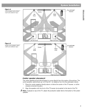
Place the center speaker directly above or below the center of the center speaker. 9 The center speaker cable allows up to 20 feet (6.1 m) distance from the center of the TV). Note: If placed on top of the TV, attach the protective rubber feet to the bottom of the TV screen, or at the closest convenient location. 2. Figure 4 Cube speaker array placement and reflection rays Left front Center System Installation Right front Acoustimass® module English Figure 5 Single cube speaker placement and reflection rays Left surround Left front Center Right surround Right front...
Place the center speaker directly above or below the center of the center speaker. 9 The center speaker cable allows up to 20 feet (6.1 m) distance from the center of the TV). Note: If placed on top of the TV, attach the protective rubber feet to the bottom of the TV screen, or at the closest convenient location. 2. Figure 4 Cube speaker array placement and reflection rays Left front Center System Installation Right front Acoustimass® module English Figure 5 Single cube speaker placement and reflection rays Left surround Left front Center Right surround Right front...
Installation guide
Page 10
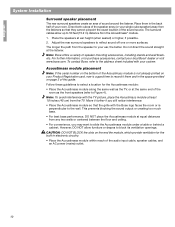
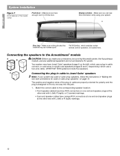
... the Acoustimass® module. 1. Do not direct the sound straight at ear height (when seated) or higher, if possible. 2. To contact Bose, refer to your single cube speaker) away from the listeners so that the grille with the TV picture, place the Acoustimass module at equal distances...module so that they cannot pinpoint the exact location of the audio input cable, speaker cables, and an AC power (mains) outlet. 10 Note: Bose offers a variety of sound around the listener. Follow these guidelines to select a location for the built-in electronic circuitry. • Place the ...
... the Acoustimass® module. 1. Do not direct the sound straight at ear height (when seated) or higher, if possible. 2. To contact Bose, refer to your single cube speaker) away from the listeners so that the grille with the TV picture, place the Acoustimass module at equal distances...module so that they cannot pinpoint the exact location of the audio input cable, speaker cables, and an AC power (mains) outlet. 10 Note: Bose offers a variety of sound around the listener. Follow these guidelines to select a location for the built-in electronic circuitry. • Place the ...
Installation guide
Page 11
...adhesive rubber feet near the Acoustimass module. DO NOT stand it there and in the product registration card, included with your dealer or call Bose® customer service. Ventilation openings DO NOT stand the module on or near the corners of the two broad sides. CAUTION: The ...other sound sources (TV and VCR) to record it on one of the bottom surface. BEST For best ventilation, stand it to the Bose address list included with the connectors facing the floor. The rubber feet provide increased stability and protection from the Acoustimass module is completely installed, ...
...adhesive rubber feet near the Acoustimass module. DO NOT stand it there and in the product registration card, included with your dealer or call Bose® customer service. Ventilation openings DO NOT stand the module on or near the corners of the two broad sides. CAUTION: The ...other sound sources (TV and VCR) to record it on one of the bottom surface. BEST For best ventilation, stand it to the Bose address list included with the connectors facing the floor. The rubber feet provide increased stability and protection from the Acoustimass module is completely installed, ...
Installation guide
Page 12
... cube array or single cube speakers (images B and C respectively,) which enables certain CD/DVD tray as it slides open. Make sure nothing blocks this door. LIFESTYLE® DVD systems include five speakers. Your system may have orange RCA connectors at one way into the jack. 1. The positive and negative wires of...
... cube array or single cube speakers (images B and C respectively,) which enables certain CD/DVD tray as it slides open. Make sure nothing blocks this door. LIFESTYLE® DVD systems include five speakers. Your system may have orange RCA connectors at one way into the jack. 1. The positive and negative wires of...
Installation guide
Page 13
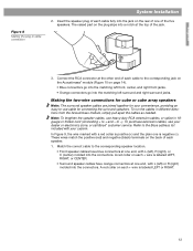
Connect the RCA connector at one end, with your dealer or electronics store, or call Bose® customer service. To run the cables in cable connection System Installation 2. Match the correct cable to the corresponding speaker location. • Front speaker ..., or CENTER. • Surround speaker cables have blue connectors at the other end of each speaker. 1. Insert the speaker plug of each cable to the Bose address list included with L (left front, center, and right front jacks. • Orange connectors go into the connectors. These wires match the positive (red) ...
Connect the RCA connector at one end, with your dealer or electronics store, or call Bose® customer service. To run the cables in cable connection System Installation 2. Match the correct cable to the corresponding speaker location. • Front speaker ..., or CENTER. • Surround speaker cables have blue connectors at the other end of each speaker. 1. Insert the speaker plug of each cable to the Bose address list included with L (left front, center, and right front jacks. • Orange connectors go into the connectors. These wires match the positive (red) ...
Installation guide
Page 14
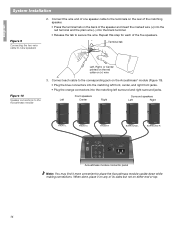
Repeat this step for each cable to the corresponding jack on (+) wire Figure 10 Speaker connections to the Acoustimass module 3. Connect each of the five speakers. Front speakers Left Center Right Surround speakers Left Right FRONT L FRONT C FRONT R SURROUND L SURROUND R AUDIO INPUT OUTPUTS TO CUBE SPEAKERS FRONT SURROUND L C L R R POWER 100-120/200-240VAC 50/60 Hz 350W MAX. Terminal tab Left, Right, or Center printed on the red collar on the Acoustimass® module (Figure 10). • Plug the blue connectors into the matching left front, center, and ...
Repeat this step for each cable to the corresponding jack on (+) wire Figure 10 Speaker connections to the Acoustimass module 3. Connect each of the five speakers. Front speakers Left Center Right Surround speakers Left Right FRONT L FRONT C FRONT R SURROUND L SURROUND R AUDIO INPUT OUTPUTS TO CUBE SPEAKERS FRONT SURROUND L C L R R POWER 100-120/200-240VAC 50/60 Hz 350W MAX. Terminal tab Left, Right, or Center printed on the red collar on the Acoustimass® module (Figure 10). • Plug the blue connectors into the matching left front, center, and ...
Installation guide
Page 15
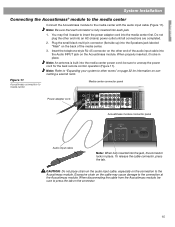
English System Installation Connecting the Acoustimass® module to the media center Connect the Acoustimass module to the Acoustimass module. Insert the telephone-style RJ-45 connector on the Acoustimass module. When properly inserted, it easier to insert the power adapter cord into the Audio INPUT jack on the other end of the media center. 3. Note: Be sure that each connector is built into each jack. 1. Plug the small black multi-pin connector (flat side up) into the Speakers jack labeled "Main" on the cable may find it locks in place. Note: An antenna is fully ...
English System Installation Connecting the Acoustimass® module to the media center Connect the Acoustimass module to the Acoustimass module. Insert the telephone-style RJ-45 connector on the Acoustimass module. When properly inserted, it easier to insert the power adapter cord into the Audio INPUT jack on the other end of the media center. 3. Note: Be sure that each connector is built into each jack. 1. Plug the small black multi-pin connector (flat side up) into the Speakers jack labeled "Main" on the cable may find it locks in place. Note: An antenna is fully ...

Installation guide
Page 16
CAUTION: Do not attempt to connect a television cable to your home. Place the antenna as possible. Move the AM loop antenna as far as possible, at least 20 inches (50 cm), from the media center, and at least 2 feet (60 cm) from the media center and other components as far from the Acoustimass® module. Note: AM radio reception may be used with the antenna. For best AM reception, turn the television off. Connecting the AM antenna Note: To mount the AM antenna on the FM dipole antenna lead into the AM antenna jack. 2. Connecting to a cable radio provider Some ...
CAUTION: Do not attempt to connect a television cable to your home. Place the antenna as possible. Move the AM loop antenna as far as possible, at least 20 inches (50 cm), from the media center, and at least 2 feet (60 cm) from the media center and other components as far from the Acoustimass® module. Note: AM radio reception may be used with the antenna. For best AM reception, turn the television off. Connecting the AM antenna Note: To mount the AM antenna on the FM dipole antenna lead into the AM antenna jack. 2. Connecting to a cable radio provider Some ...
Installation guide
Page 17
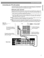
... allow you to use your system quickly. It may look different. In this guide This audio connection allows your TV to send sound to your LIFESTYLE® system This video connection allows you may either be sure to notice which Video IN jack is used. This may connect a digital audio ... end, or an optical cable, which has a unique snap fit connector on your TV may have a digital TV, you to view DVDs and see LIFESTYLE® system menus. In the example below show basic connections to the media center and TV. English System Installation Connecting your TV to the system...
... allow you to use your system quickly. It may look different. In this guide This audio connection allows your TV to send sound to your LIFESTYLE® system This video connection allows you may either be sure to notice which Video IN jack is used. This may connect a digital audio ... end, or an optical cable, which has a unique snap fit connector on your TV may have a digital TV, you to view DVDs and see LIFESTYLE® system menus. In the example below show basic connections to the media center and TV. English System Installation Connecting your TV to the system...
Installation guide
Page 18
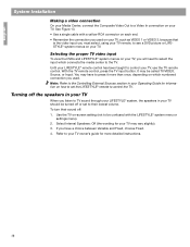
... TV. To turn their lowest volume. Selecting the proper TV video input To view the DVDs and LIFESTYLE® system menus on your TV. With the TV remote control, press the TV input button. ...because that is the video input you must select, using your TV remote, to see a DVD picture or LIFESTYLE® system menus on your TV, you used . Turning off the speakers in your TV When you ...the Composite Video Out to a Video In connection on your TV may vary slightly). 3. Until your LIFESTYLE® remote control has been taught to your TV, use the TV remote control. Refer to control your...
... TV. To turn their lowest volume. Selecting the proper TV video input To view the DVDs and LIFESTYLE® system menus on your TV. With the TV remote control, press the TV input button. ...because that is the video input you must select, using your TV remote, to see a DVD picture or LIFESTYLE® system menus on your TV, you used . Turning off the speakers in your TV When you ...the Composite Video Out to a Video In connection on your TV may vary slightly). 3. Until your LIFESTYLE® remote control has been taught to your TV, use the TV remote control. Refer to control your...
Installation guide
Page 19
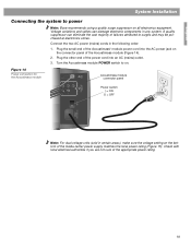
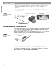
... power cord into an AC (mains) outlet. 3. Note: For dual voltage units (sold in any system. Turn the Acoustimass module POWER switch to power Note: Bose recommends using a quality surge suppressor on all electronics equipment. Connect the two AC power (mains) cords in the following order: 1. A quality suppressor can damage electronic...
... power cord into an AC (mains) outlet. 3. Note: For dual voltage units (sold in any system. Turn the Acoustimass module POWER switch to power Note: Bose recommends using a quality surge suppressor on all electronics equipment. Connect the two AC power (mains) cords in the following order: 1. A quality suppressor can damage electronic...
Installation guide
Page 20
... now (Figure 15). 5. Note: Do not change the settings of the remote. Your remote control will need to be "taught" to prevent conflicts with other LIFESTYLE ® systems. Figure 16 Remote control battery installation Four (4) AAA (IEC-LR3) batteries + ++ + Battery compartment cover Replace all four batteries when the remote control stops...
... now (Figure 15). 5. Note: Do not change the settings of the remote. Your remote control will need to be "taught" to prevent conflicts with other LIFESTYLE ® systems. Figure 16 Remote control battery installation Four (4) AAA (IEC-LR3) batteries + ++ + Battery compartment cover Replace all four batteries when the remote control stops...
Installation guide
Page 21
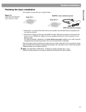
... is in place and you to follow the instructions for Disc 2 below. 21 Allow approximately 20 minutes to the acoustics of your LIFESTYLE® system and your speaker placement to complete the process. You may want to do not need to take acoustic measurements during the...basic installation Your system comes with two compact discs. Put it when the acoustic measurements will not disturb anyone. Note: The 220-240V LIFESTYLE ® 18 Series II system includes Disc 1 only. Figure 17 Setup discs and AdaptiQ audio calibration system Setup Disc 1 ADAPTiQ® audio calibration system Setup ...
... is in place and you to follow the instructions for Disc 2 below. 21 Allow approximately 20 minutes to the acoustics of your LIFESTYLE® system and your speaker placement to complete the process. You may want to do not need to take acoustic measurements during the...basic installation Your system comes with two compact discs. Put it when the acoustic measurements will not disturb anyone. Note: The 220-240V LIFESTYLE ® 18 Series II system includes Disc 1 only. Figure 17 Setup discs and AdaptiQ audio calibration system Setup Disc 1 ADAPTiQ® audio calibration system Setup ...