Owner's guide
Page 5
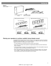
.... Figure 1 Carton contents Setting Up 20-ft (6.1m) system input cable Powered Acoustimass® module Three 20-ft (6.1m) front speaker cables Rubber feet for front center cube speaker With Acoustimass 6 System Five cube speakers With Acoustimass 10 System Five cube speaker arrays Two 50-ft (15.2m)... rear speaker cables Two 50-ft (15.2m) rear speaker cables USA/Canada Power cord (1) Europe UK/Singapore Australia Placing your speakers to create room-filling sound patterns (Figure 3). • Bose®...
.... Figure 1 Carton contents Setting Up 20-ft (6.1m) system input cable Powered Acoustimass® module Three 20-ft (6.1m) front speaker cables Rubber feet for front center cube speaker With Acoustimass 6 System Five cube speakers With Acoustimass 10 System Five cube speaker arrays Two 50-ft (15.2m)... rear speaker cables Two 50-ft (15.2m) rear speaker cables USA/Canada Power cord (1) Europe UK/Singapore Australia Placing your speakers to create room-filling sound patterns (Figure 3). • Bose®...
Owner's guide
Page 8
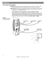
.... The other ends of the cables have blue RCA connectors at one end with the corresponding speaker location. Connecting front cube speakers to the Acoustimass module Three individual 20-foot (6.1 m) speaker cables connect the center, right, and left ), R (right), or C (center) molded ... 5 Cube speaker connections to the Acoustimass module (Figure 5). Always connect them to the powered Acoustimass® module, then connect the module to match the correct cable with L (left front cube speakers to Acoustimass module RIGHT CENTER LEFT Audio Input Left Center Right Front Front Front ...
.... The other ends of the cables have blue RCA connectors at one end with the corresponding speaker location. Connecting front cube speakers to the Acoustimass module Three individual 20-foot (6.1 m) speaker cables connect the center, right, and left ), R (right), or C (center) molded ... 5 Cube speaker connections to the Acoustimass module (Figure 5). Always connect them to the powered Acoustimass® module, then connect the module to match the correct cable with L (left front cube speakers to Acoustimass module RIGHT CENTER LEFT Audio Input Left Center Right Front Front Front ...
Owner's guide
Page 10
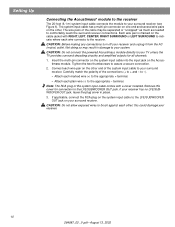
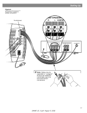
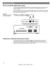
...cable may result in place. 3. If your surround receiver. CAUTION: Do not connect the powered Acoustimass module directly to the LFE/SUBWOOFER OUT jack on the system input cable to your TV unless the TV provides surround decoding circuitry and amplified outputs for ... on the other ; Remove this could damage your surround receiver (see Figure 6). Setting Up Connecting the Acoustimass® module to the receiver The 20-foot (6.1 m) system input cable connects the module to the LFE/SUBWOOFER OUT jack. Tighten the two thumbscrews to your receiver and unplug...
...cable may result in place. 3. If your surround receiver. CAUTION: Do not connect the powered Acoustimass module directly to the LFE/SUBWOOFER OUT jack on the system input cable to your TV unless the TV provides surround decoding circuitry and amplified outputs for ... on the other ; Remove this could damage your surround receiver (see Figure 6). Setting Up Connecting the Acoustimass® module to the receiver The 20-foot (6.1 m) system input cable connects the module to the LFE/SUBWOOFER OUT jack. Tighten the two thumbscrews to your receiver and unplug...
Owner's guide
Page 11
Figure 6 Acoustimass® module to receiver connections Thumbscrews Audio Output Left Rear Right Rear Audio Input Left Center Right Front Front Front Setting Up FRONT SPEAKERS A R L CENTER FRONT SPEAKERS A R L CENTER SURROUND SPEAKERS R L LFE/SUBWOOFER OUT Note: Cables may be separated or "unzipped" as much as needed to comfortably reach the surround receiver connections. 11 264887_00 _V.pdf • August 13, 2002
Figure 6 Acoustimass® module to receiver connections Thumbscrews Audio Output Left Rear Right Rear Audio Input Left Center Right Front Front Front Setting Up FRONT SPEAKERS A R L CENTER FRONT SPEAKERS A R L CENTER SURROUND SPEAKERS R L LFE/SUBWOOFER OUT Note: Cables may be separated or "unzipped" as much as needed to comfortably reach the surround receiver connections. 11 264887_00 _V.pdf • August 13, 2002
Owner's guide
Page 13
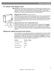
... The LFE level control on movie soundtracks. tive level of the LFE channel to LARGE in your digital surround sound receiver Your Acoustimass 6 or Acoustimass 10 speakers are compatible with the output from electrical stress or overload. Integrated Signal Processing assures full bass reproduction for a majority ...it to reduce the bass level of damage from digital surround receivers. The factory or detent setting is normal operation and indicates that power input may be exceeding safe levels. If the room sounds "thin" or lacks bass, turn the knob in a clockwise direction to ON...
... The LFE level control on movie soundtracks. tive level of the LFE channel to LARGE in your digital surround sound receiver Your Acoustimass 6 or Acoustimass 10 speakers are compatible with the output from electrical stress or overload. Integrated Signal Processing assures full bass reproduction for a majority ...it to reduce the bass level of damage from digital surround receivers. The factory or detent setting is normal operation and indicates that power input may be exceeding safe levels. If the room sounds "thin" or lacks bass, turn the knob in a clockwise direction to ON...
Owner's guide
Page 14
... owner's guide for this process vary, depending on the brand and model of your DVD player to the digital audio input on a surround receiver Note: Use the OPTICAL or COAXIAL OR digital input connections, but not both. Before you set the surround-sound center mode of your receiver to the owner's guide...
... owner's guide for this process vary, depending on the brand and model of your DVD player to the digital audio input on a surround receiver Note: Use the OPTICAL or COAXIAL OR digital input connections, but not both. Before you set the surround-sound center mode of your receiver to the owner's guide...
Owner's guide
Page 15
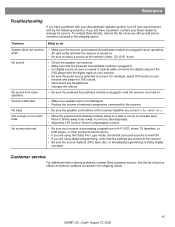
...System does not function • Make sure the receiver and powered Acoustimass module are using the Dolby Pro-Logic mode, check that surround-sound is turned ON. • If you still have a problem with the digital input on your receiver. • Be sure the audio source selected is... service For additional help in the shipping carton. Reference Troubleshooting If you have a problem, contact your Bose® dealer to select a source at all AC wall outlet and that the powered Acoustimass module is plugged in. • For digital sound, be sure a coaxial or optical cable connects ...
...System does not function • Make sure the receiver and powered Acoustimass module are using the Dolby Pro-Logic mode, check that surround-sound is turned ON. • If you still have a problem with the digital input on your receiver. • Be sure the audio source selected is... service For additional help in the shipping carton. Reference Troubleshooting If you have a problem, contact your Bose® dealer to select a source at all AC wall outlet and that the powered Acoustimass module is plugged in. • For digital sound, be sure a coaxial or optical cable connects ...
Owner's guide
Page 17
... Warranty period Your Acoustimass® speaker system is covered by a limited transferable warranty. Accessories • Table stands: UTS-20B (black), UTS-20W (white) • Floor stands: UFS-20B (black), UFS-20W (white) • Wall brackets: UB-20B (black), UB-20W (white) • Module input cable adapter for ...on the warranty card that came with existing wiring: PN 267139-001 (black) PN 267139-002 (white) • Module 20 ft (6.1 m) input extension cable: PN198221-001 (black) PN198221-002 (white) 17 264887_00 _V.pdf • August 13, 2002 Details of the warranty are provided on...
... Warranty period Your Acoustimass® speaker system is covered by a limited transferable warranty. Accessories • Table stands: UTS-20B (black), UTS-20W (white) • Floor stands: UFS-20B (black), UFS-20W (white) • Wall brackets: UB-20B (black), UB-20W (white) • Module input cable adapter for ...on the warranty card that came with existing wiring: PN 267139-001 (black) PN 267139-002 (white) • Module 20 ft (6.1 m) input extension cable: PN198221-001 (black) PN198221-002 (white) 17 264887_00 _V.pdf • August 13, 2002 Details of the warranty are provided on...


