Owner's guide
Page 5
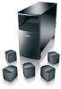
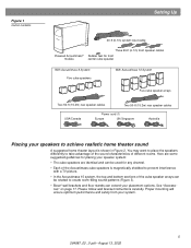
...Bose® wall brackets and floor stands can be rotated to prevent interference with a TV picture. • In the Acoustimass 10 system, the top and bottom sections of the Acoustimass cube speakers is shown in Figure 2. Figure 1 Carton contents Setting Up 20-ft (6.1m) system input cable Powered Acoustimass...® module Three 20-ft (6.1m) front speaker cables Rubber feet for any channel. • Each of the cube speaker arrays can extend your placement ...
...Bose® wall brackets and floor stands can be rotated to prevent interference with a TV picture. • In the Acoustimass 10 system, the top and bottom sections of the Acoustimass cube speakers is shown in Figure 2. Figure 1 Carton contents Setting Up 20-ft (6.1m) system input cable Powered Acoustimass...® module Three 20-ft (6.1m) front speaker cables Rubber feet for any channel. • Each of the cube speaker arrays can extend your placement ...
Owner's guide
Page 8
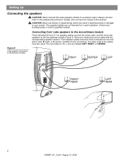
...RCA connectors at one end with the corresponding speaker location. The supplied cables are labeled LEFT, RIGHT, or CENTER. Always connect them to the powered Acoustimass® module, then connect the module to Acoustimass module RIGHT CENTER LEFT Audio Input Left Center Right Front Front Front ... • August 13, 2002 The red collars on the + wire are not intended for in electrical shock or damage to the Acoustimass module Three individual 20-foot (6.1 m) speaker cables connect the center, right, and left ), R (right), or C (center) molded into the connectors. Be sure to match ...
...RCA connectors at one end with the corresponding speaker location. The supplied cables are labeled LEFT, RIGHT, or CENTER. Always connect them to the powered Acoustimass® module, then connect the module to Acoustimass module RIGHT CENTER LEFT Audio Input Left Center Right Front Front Front ... • August 13, 2002 The red collars on the + wire are not intended for in electrical shock or damage to the Acoustimass module Three individual 20-foot (6.1 m) speaker cables connect the center, right, and left ), R (right), or C (center) molded into the connectors. Be sure to match ...
Owner's guide
Page 9
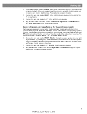
...rear cube speaker is connected to the Acoustimass module with LR (left rear) and RR (right rear) molded into the Center Front, Right Front, and Left Front blue RCA jacks, respectively, on the + wires are labeled LEFT REAR and RIGHT REAR. 1. Rear speaker cables have two wires. Connect the wire ... terminal tab on your right as you face the TV). Connect the wire pair marked LEFT to match the correct cable with the corresponding speaker location. Press the terminal tab on the Acoustimass module. 9 264887_00 _V.pdf • August 13, 2002 Plug the other end of the cube speaker. Be ...
...rear cube speaker is connected to the Acoustimass module with LR (left rear) and RR (right rear) molded into the Center Front, Right Front, and Left Front blue RCA jacks, respectively, on the + wires are labeled LEFT REAR and RIGHT REAR. 1. Rear speaker cables have two wires. Connect the wire ... terminal tab on your right as you face the TV). Connect the wire pair marked LEFT to match the correct cable with the corresponding speaker location. Press the terminal tab on the Acoustimass module. 9 264887_00 _V.pdf • August 13, 2002 Plug the other end of the cube speaker. Be ...
Owner's guide
Page 10
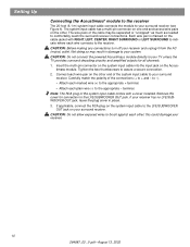
... two thumbscrews to your receiver. 10 264887_00 _V.pdf • August 13, 2002 Setting Up Connecting the Acoustimass® module to the receiver The 20-foot (6.1 m) system input cable connects the module to your TV unless the TV provides surround decoding circuitry and amplified outputs for... connection to the LFE/SUBWOOFER OUT jack. Each wire pair is marked on the cable jacket with a cover installed. CAUTION: Do not connect the powered Acoustimass module directly to + and - Note: The RCA plug of the connections (+ to your surround receiver (see ...
... two thumbscrews to your receiver. 10 264887_00 _V.pdf • August 13, 2002 Setting Up Connecting the Acoustimass® module to the receiver The 20-foot (6.1 m) system input cable connects the module to your TV unless the TV provides surround decoding circuitry and amplified outputs for... connection to the LFE/SUBWOOFER OUT jack. Each wire pair is marked on the cable jacket with a cover installed. CAUTION: Do not connect the powered Acoustimass module directly to + and - Note: The RCA plug of the connections (+ to your surround receiver (see ...
Owner's guide
Page 11
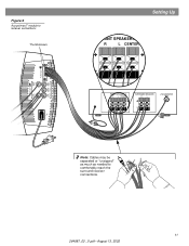
Figure 6 Acoustimass® module to receiver connections Thumbscrews Audio Output Left Rear Right Rear Audio Input Left Center Right Front Front Front Setting Up FRONT SPEAKERS A R L CENTER FRONT SPEAKERS A R L CENTER SURROUND SPEAKERS R L LFE/SUBWOOFER OUT Note: Cables may be separated or "unzipped" as much as needed to comfortably reach the surround receiver connections. 11 264887_00 _V.pdf • August 13, 2002
Figure 6 Acoustimass® module to receiver connections Thumbscrews Audio Output Left Rear Right Rear Audio Input Left Center Right Front Front Front Setting Up FRONT SPEAKERS A R L CENTER FRONT SPEAKERS A R L CENTER SURROUND SPEAKERS R L LFE/SUBWOOFER OUT Note: Cables may be separated or "unzipped" as much as needed to comfortably reach the surround receiver connections. 11 264887_00 _V.pdf • August 13, 2002
Owner's guide
Page 15
... an operating at all AC wall outlet and that the powered Acoustimass module is plugged in. • For digital sound, be sure a coaxial or optical cable connects the digital output of the DVD player with your Acoustimass® speaker system, turn off your Bose® dealer to arrange for DVD sound. • Disconnect any...
... an operating at all AC wall outlet and that the powered Acoustimass module is plugged in. • For digital sound, be sure a coaxial or optical cable connects the digital output of the DVD player with your Acoustimass® speaker system, turn off your Bose® dealer to arrange for DVD sound. • Disconnect any...
Owner's guide
Page 17
... 267139-001 (black) PN 267139-002 (white) • Module 20 ft (6.1 m) input extension cable: PN198221-001 (black) PN198221-002 (white) 17 264887_00 _V.pdf • August 13, 2002 Reference Warranty period Your Acoustimass® speaker system is covered by a limited transferable warranty. Accessories • Table stands: UTS-20B...white) • Floor stands: UFS-20B (black), UFS-20W (white) • Wall brackets: UB-20B (black), UB-20W (white) • Module input cable adapter for use with existing wiring: PN 267138-001 (black) PN 267138-002 (white) • Module-to Bose®.
... 267139-001 (black) PN 267139-002 (white) • Module 20 ft (6.1 m) input extension cable: PN198221-001 (black) PN198221-002 (white) 17 264887_00 _V.pdf • August 13, 2002 Reference Warranty period Your Acoustimass® speaker system is covered by a limited transferable warranty. Accessories • Table stands: UTS-20B...white) • Floor stands: UFS-20B (black), UFS-20W (white) • Wall brackets: UB-20B (black), UB-20W (white) • Module input cable adapter for use with existing wiring: PN 267138-001 (black) PN 267138-002 (white) • Module-to Bose®.

