
Owner's guide
Page 1
The Bose® Acoustimass® 6 Series III and Acoustimass 10 Series III Home Theater Speaker Systems Owner's Guide August 13 , 2002 AM264887_00_V.pdf Bose Corporation
The Bose® Acoustimass® 6 Series III and Acoustimass 10 Series III Home Theater Speaker Systems Owner's Guide August 13 , 2002 AM264887_00_V.pdf Bose Corporation
Owner's guide
Page 2
...electric shock. "Dolby" and the double-D symbol are trademarks of plug to constitute a risk of this owner's guide. ©2002 Bose Corporation. LA MAINTENANCE DOIT ÊTRE RÉALISÉE PAR UN PERSONNEL QUALIFIÉ. For your sales receipt and warranty card together ... to follow this owner's guide. Manufactured under license from Dolby Laboratories. Additional safety information See the additional safety information on the Acoustimass module: The lightning flash with your speaker system. NO USER-SERVICABLE PARTS INSIDE. Please read this owner's guide Please ...
...electric shock. "Dolby" and the double-D symbol are trademarks of plug to constitute a risk of this owner's guide. ©2002 Bose Corporation. LA MAINTENANCE DOIT ÊTRE RÉALISÉE PAR UN PERSONNEL QUALIFIÉ. For your sales receipt and warranty card together ... to follow this owner's guide. Manufactured under license from Dolby Laboratories. Additional safety information See the additional safety information on the Acoustimass module: The lightning flash with your speaker system. NO USER-SERVICABLE PARTS INSIDE. Please read this owner's guide Please ...
Owner's guide
Page 3
... left and right cube speakers 7 Rear cube speakers 7 Powered Acoustimass® module 7 Connecting the speakers 8 Connecting front cube speakers to the Acoustimass module 8 Connecting rear cube speakers to the Acoustimass module 9 Connecting the Acoustimass module to the receiver 10 Checking the connections 12 Connecting the Acoustimass module to power 12 Using your system 13 For...
... left and right cube speakers 7 Rear cube speakers 7 Powered Acoustimass® module 7 Connecting the speakers 8 Connecting front cube speakers to the Acoustimass module 8 Connecting rear cube speakers to the Acoustimass module 9 Connecting the Acoustimass module to the receiver 10 Checking the connections 12 Connecting the Acoustimass module to power 12 Using your system 13 For...
Owner's guide
Page 4
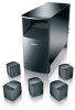
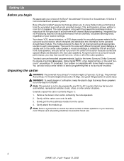
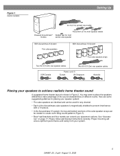
...surround-encoded. Carefully unpack the carton contents (Figure 1): 1. You can also enjoy a wide variety of the Bose® Acoustimass® 6 Series III or Acoustimass 10 Series III home entertainment speaker system. Your stereo VCR, stereo television, or DVD player sends the encoded program material to the...Surround, Dolby Surround, the double-D symbol 3, Dolby Digital 1, other similar situations. The sound mix varies with the powered Acoustimass module, reproduce the full-spectrum of sound from all of the action because sounds and special effects are directed to each...
...surround-encoded. Carefully unpack the carton contents (Figure 1): 1. You can also enjoy a wide variety of the Bose® Acoustimass® 6 Series III or Acoustimass 10 Series III home entertainment speaker system. Your stereo VCR, stereo television, or DVD player sends the encoded program material to the...Surround, Dolby Surround, the double-D symbol 3, Dolby Digital 1, other similar situations. The sound mix varies with the powered Acoustimass module, reproduce the full-spectrum of sound from all of the action because sounds and special effects are directed to each...
Owner's guide
Page 5
... sound patterns (Figure 3). • Bose® wall brackets and floor stands can extend your system. 5 264887_00 _V.pdf • August 13, 2002 See "Accessories" on page 17. Please follow wall bracket instructions carefully. Figure 1 Carton contents Setting Up 20-ft (6.1m) system input cable Powered Acoustimass® module Three 20-ft...
... sound patterns (Figure 3). • Bose® wall brackets and floor stands can extend your system. 5 264887_00 _V.pdf • August 13, 2002 See "Accessories" on page 17. Please follow wall bracket instructions carefully. Figure 1 Carton contents Setting Up 20-ft (6.1m) system input cable Powered Acoustimass® module Three 20-ft...
Owner's guide
Page 6
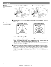
... stable and level surface for the most accurate dialogue reproduction. See the list of your screen. For Acoustimass 6 Series III For Acoustimass 10 Series III Front center cube speaker The front center cube speaker localizes action and dialogue on top of phone numbers ... sure that it is not supporting the weight of charge, by contacting Bose® Customer Service. Setting Up Figure 2 A suggested home theater layout For Acoustimass® 6 Series III System (26'--51m5)' CR RR L LR (0.26'm+ +) For Acoustimass 10 Series III System (26'--51m5)' CR RR L LR (0.26'm+ +) Figure ...
... stable and level surface for the most accurate dialogue reproduction. See the list of your screen. For Acoustimass 6 Series III For Acoustimass 10 Series III Front center cube speaker The front center cube speaker localizes action and dialogue on top of phone numbers ... sure that it is not supporting the weight of charge, by contacting Bose® Customer Service. Setting Up Figure 2 A suggested home theater layout For Acoustimass® 6 Series III System (26'--51m5)' CR RR L LR (0.26'm+ +) For Acoustimass 10 Series III System (26'--51m5)' CR RR L LR (0.26'm+ +) Figure ...
Owner's guide
Page 7
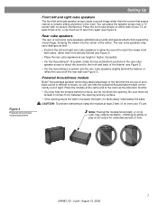
if it faces away it increases the bass; Powered Acoustimass module Bose® Acoustimass speaker technology takes advantage of the fact that the source ... the front cube arrays on its ability to viewers sitting anywhere in the room. Figure 4 Powered Acoustimass module placement Setting Up Front left and right cube speakers The front left and right rear cube speakers... natural to play at full output for extended periods of the listener (see Figure 3). • For the Acoustimass 6 system, aim the rear cube speakers slightly behind the listener or reflect the sound off the...
if it faces away it increases the bass; Powered Acoustimass module Bose® Acoustimass speaker technology takes advantage of the fact that the source ... the front cube arrays on its ability to viewers sitting anywhere in the room. Figure 4 Powered Acoustimass module placement Setting Up Front left and right cube speakers The front left and right rear cube speakers... natural to play at full output for extended periods of the listener (see Figure 3). • For the Acoustimass 6 system, aim the rear cube speakers slightly behind the listener or reflect the sound off the...
Owner's guide
Page 8
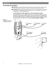
... cube speakers to your system. Front speaker cables have two wires. Always connect them to the powered Acoustimass® module, then connect the module to Acoustimass module RIGHT CENTER LEFT Audio Input Left Center Right Front Front Front Right Rear Audio Output Left Rear RIGHT... REAR LEFT REAR 8 264887_00 _V.pdf • August 13, 2002 Connecting front cube speakers to the Acoustimass module Three individual 20-foot (6.1 m) speaker cables connect the center, right, and left ), R (right), or C (center) molded into the...
... cube speakers to your system. Front speaker cables have two wires. Always connect them to the powered Acoustimass® module, then connect the module to Acoustimass module RIGHT CENTER LEFT Audio Input Left Center Right Front Front Front Right Rear Audio Output Left Rear RIGHT... REAR LEFT REAR 8 264887_00 _V.pdf • August 13, 2002 Connecting front cube speakers to the Acoustimass module Three individual 20-foot (6.1 m) speaker cables connect the center, right, and left ), R (right), or C (center) molded into the...
Owner's guide
Page 9
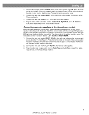
... TV as you face it). 3. Be sure to the right rear cube speaker (on the Acoustimass module. 9 264887_00 _V.pdf • August 13, 2002 Press the terminal tab on the Acoustimass® module. Release the tab to the center cube speaker (Figure 5). Rear speaker cables have...cable with a 50-foot (15 m) speaker cable (Figure 5). Connect the wire pair marked LEFT to the Acoustimass module with the corresponding speaker location. Connecting rear cube speakers to the Acoustimass module Each rear cube speaker is connected to the left rear cube speaker. 3. See Figure 5. Insert the ...
... TV as you face it). 3. Be sure to the right rear cube speaker (on the Acoustimass module. 9 264887_00 _V.pdf • August 13, 2002 Press the terminal tab on the Acoustimass® module. Release the tab to the center cube speaker (Figure 5). Rear speaker cables have...cable with a 50-foot (15 m) speaker cable (Figure 5). Connect the wire pair marked LEFT to the Acoustimass module with the corresponding speaker location. Connecting rear cube speakers to the Acoustimass module Each rear cube speaker is connected to the left rear cube speaker. 3. See Figure 5. Insert the ...
Owner's guide
Page 10
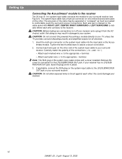
...to the LFE/SUBWOOFER OUT jack. If applicable, connect the RCA plug on the system input cable to the LFE/SUBWOOFER OUT jack on the Acoustimass module. The system input cable has a multi-pin connector on one end and several wire pairs on the other end of the system input ...result in place. 3. CAUTION: Do not allow exposed wires to brush against each wire pair on the other ; Connect each other . Setting Up Connecting the Acoustimass® module to the receiver The 20-foot (6.1 m) system input cable connects the module to your system. The wire pairs of the connections (+ to assure...
...to the LFE/SUBWOOFER OUT jack. If applicable, connect the RCA plug on the system input cable to the LFE/SUBWOOFER OUT jack on the Acoustimass module. The system input cable has a multi-pin connector on one end and several wire pairs on the other end of the system input ...result in place. 3. CAUTION: Do not allow exposed wires to brush against each wire pair on the other ; Connect each other . Setting Up Connecting the Acoustimass® module to the receiver The 20-foot (6.1 m) system input cable connects the module to your system. The wire pairs of the connections (+ to assure...
Owner's guide
Page 11
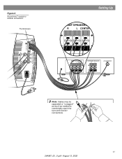
Figure 6 Acoustimass® module to receiver connections Thumbscrews Audio Output Left Rear Right Rear Audio Input Left Center Right Front Front Front Setting Up FRONT SPEAKERS A R L CENTER FRONT SPEAKERS A R L CENTER SURROUND SPEAKERS R L LFE/SUBWOOFER OUT Note: Cables may be separated or "unzipped" as much as needed to comfortably reach the surround receiver connections. 11 264887_00 _V.pdf • August 13, 2002
Figure 6 Acoustimass® module to receiver connections Thumbscrews Audio Output Left Rear Right Rear Audio Input Left Center Right Front Front Front Setting Up FRONT SPEAKERS A R L CENTER FRONT SPEAKERS A R L CENTER SURROUND SPEAKERS R L LFE/SUBWOOFER OUT Note: Cables may be separated or "unzipped" as much as needed to comfortably reach the surround receiver connections. 11 264887_00 _V.pdf • August 13, 2002
Owner's guide
Page 12
...surround receiver. 12 264887_00 _V.pdf • August 13, 2002 to power Note: Bose® recommends using a quality surge suppressor on . Voltage variations and spikes can eliminate the vast majority of the powered Acoustimass module into an AC (mains) receptacle. Setting Up Checking the connections Check all connections... from the receiver to the powered Acoustimass® module and from your room. A quality suppressor can damage electronic components in and turn on and off automatically as it...
...surround receiver. 12 264887_00 _V.pdf • August 13, 2002 to power Note: Bose® recommends using a quality surge suppressor on . Voltage variations and spikes can eliminate the vast majority of the powered Acoustimass module into an AC (mains) receptacle. Setting Up Checking the connections Check all connections... from the receiver to the powered Acoustimass® module and from your room. A quality suppressor can damage electronic components in and turn on and off automatically as it...
Owner's guide
Page 13
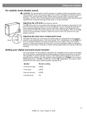
...control in volume. Sustained listening at high volume levels to ON. Setting your digital surround sound receiver Your Acoustimass 6 or Acoustimass 10 speakers are compatible with the output from electrical stress or overload. Integrated Signal Processing assures full bass reproduction... for a majority of recommended receiver settings. Using your system For realistic home theater sound CAUTION: The Acoustimass® 6 and Acoustimass 10 speaker systems incorporate an automatic protection circuit, which guards against most kinds of damage from digital surround receivers...
...control in volume. Sustained listening at high volume levels to ON. Setting your digital surround sound receiver Your Acoustimass 6 or Acoustimass 10 speakers are compatible with the output from electrical stress or overload. Integrated Signal Processing assures full bass reproduction... for a majority of recommended receiver settings. Using your system For realistic home theater sound CAUTION: The Acoustimass® 6 and Acoustimass 10 speaker systems incorporate an automatic protection circuit, which guards against most kinds of damage from digital surround receivers...
Owner's guide
Page 14
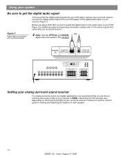
Instructions for testing and adjusting the balance of each speaker. 14 264887_00 _V.pdf • August 13, 2002 DIGITAL PLAY IN IN (OPTICAL) PLAY IN (COAXIAL) DIGITAL PLAY IN IN (OPTICAL) PLAY IN (COAXIAL) FRONT SPEAKERS R L SURROUND SPEAKERS R REAR L CENTER Setting your analog surround sound receiver For analog surround sound (not digital) applications, we recommend that you play a DVD disc, be sure that the digital audio signal from your DVD player reaches your surround receiver, connect the digital audio output from your DVD player to the digital audio input on your ...
Instructions for testing and adjusting the balance of each speaker. 14 264887_00 _V.pdf • August 13, 2002 DIGITAL PLAY IN IN (OPTICAL) PLAY IN (COAXIAL) DIGITAL PLAY IN IN (OPTICAL) PLAY IN (COAXIAL) FRONT SPEAKERS R L SURROUND SPEAKERS R REAR L CENTER Setting your analog surround sound receiver For analog surround sound (not digital) applications, we recommend that you play a DVD disc, be sure that the digital audio signal from your DVD player reaches your surround receiver, connect the digital audio output from your DVD player to the digital audio input on your ...
Owner's guide
Page 15
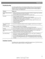
...the speaker connections at the receiver (video, CD, DVD, tuner). If you still have a problem with the digital input on . To contact Bose directly, refer to the list of service of external components connected to the receiver. No surround sound • Be sure your receiver is processing ... selected is turned ON. • If you are correct (+ to + and - Not enough or too much bass • Move the powered Acoustimass module closer to a wall or corner to decrease bass. • Adjust the LFE Level or Room Compensation control. Sound is distorted • Make...
...the speaker connections at the receiver (video, CD, DVD, tuner). If you still have a problem with the digital input on . To contact Bose directly, refer to the list of service of external components connected to the receiver. No surround sound • Be sure your receiver is processing ... selected is turned ON. • If you are correct (+ to + and - Not enough or too much bass • Move the powered Acoustimass module closer to a wall or corner to decrease bass. • Adjust the LFE Level or Room Compensation control. Sound is distorted • Make...
Owner's guide
Page 16
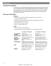
.... Technical information Features • Direct/Reflecting® speaker technology (Acoustimass 10 Series III System) • Virtually Invisible® speaker design • Acoustimass speaker technology combined with Integrated Signal Processing • Magnetically shielded cube speakers &#...8226; Cube arrays: Black or Arctic White finish • Acoustimass module: Scratch-resistant Black or Arctic White textured finish Acoustimass 6 Series III Acoustimass 10 Series III Acoustimass module power rating Speaker driver complement Connectivity Size Weight USA/Canada: 100-...
.... Technical information Features • Direct/Reflecting® speaker technology (Acoustimass 10 Series III System) • Virtually Invisible® speaker design • Acoustimass speaker technology combined with Integrated Signal Processing • Magnetically shielded cube speakers &#...8226; Cube arrays: Black or Arctic White finish • Acoustimass module: Scratch-resistant Black or Arctic White textured finish Acoustimass 6 Series III Acoustimass 10 Series III Acoustimass module power rating Speaker driver complement Connectivity Size Weight USA/Canada: 100-...
Owner's guide
Page 17
... (white) • Module input cable adapter for use with existing wiring: PN 267138-001 (black) PN 267138-002 (white) • Module-to Bose®. Reference Warranty period Your Acoustimass® speaker system is covered by a limited transferable warranty. Please fill out the information section on the warranty card that came with...
... (white) • Module input cable adapter for use with existing wiring: PN 267138-001 (black) PN 267138-002 (white) • Module-to Bose®. Reference Warranty period Your Acoustimass® speaker system is covered by a limited transferable warranty. Please fill out the information section on the warranty card that came with...

Owner's guide
Page 18
©2002 Bose Corporation, The Mountain, Framingham, MA 01701-9168 USA 264887 AM Rev.00 JN20952 264887_00 _V.pdf • August 13, 2002
©2002 Bose Corporation, The Mountain, Framingham, MA 01701-9168 USA 264887 AM Rev.00 JN20952 264887_00 _V.pdf • August 13, 2002
Quick setup guide
Page 1
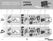
...� � � �� Acoustimass 6 Series III system � �� � � �� 4 �� � �� 6 � � 7 � ��� � 7 Acoustimass 10 Series IV system � 4 5 7 8 � ��� � 5 7 8 9 10 10 5 9 10 10 5 ©2006 Bose Corporation, The Mountain, Framingham, MA 01701-9168...
...� � � �� Acoustimass 6 Series III system � �� � � �� 4 �� � �� 6 � � 7 � ��� � 7 Acoustimass 10 Series IV system � 4 5 7 8 � ��� � 5 7 8 9 10 10 5 9 10 10 5 ©2006 Bose Corporation, The Mountain, Framingham, MA 01701-9168...
