Quick setup guide
Page 1
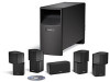
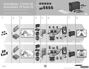
Acoustimass® 6 Series III Acoustimass 10 Series IV HOME ENTERTAINMENT SPEAKER SYSTEMS Quick setup guide • Hurtig opstillingsvejledning • Kurzanleitung • Guía rápida de instalación • Noticede montage • Guida di installazione rapida • Snelle opstellingsgids • Vägledning för snabb montering 1 2 3 4 5 6 �� � � � �� Acoustimass 6 Series III system � �� �...
Acoustimass® 6 Series III Acoustimass 10 Series IV HOME ENTERTAINMENT SPEAKER SYSTEMS Quick setup guide • Hurtig opstillingsvejledning • Kurzanleitung • Guía rápida de instalación • Noticede montage • Guida di installazione rapida • Snelle opstellingsgids • Vägledning för snabb montering 1 2 3 4 5 6 �� � � � �� Acoustimass 6 Series III system � �� �...
Owner's guide
Page 2
...as marked on the rear of Dolby Laboratories. These CAUTION marks are trademarks of the Acoustimass module: The lightning flash with this owner's guide carefully. Serial number Dealer name Dealer... reproduced, modified, distributed or otherwise used without prior written permission. Please save your speaker system. For your safety WARNING: To reduce the risk of electric shock. Manufactured under...read this owner's guide Please take the time to follow this owner's guide. ©2006 Bose Corporation. "Dolby" and the double-D symbol are located on the system, is located on...
...as marked on the rear of Dolby Laboratories. These CAUTION marks are trademarks of the Acoustimass module: The lightning flash with this owner's guide carefully. Serial number Dealer name Dealer... reproduced, modified, distributed or otherwise used without prior written permission. Please save your speaker system. For your safety WARNING: To reduce the risk of electric shock. Manufactured under...read this owner's guide Please take the time to follow this owner's guide. ©2006 Bose Corporation. "Dolby" and the double-D symbol are located on the system, is located on...
Owner's guide
Page 3
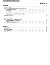
... UP 4 Before you begin 4 Unpacking the carton 4 Placing your speakers to achieve realistic home theater sound 5 Front left and right speakers 6 Center speaker 6 Rear speakers 6 Powered Acoustimass® module 7 Making the connections 7 Connecting speakers to the Acoustimass module 7 Connecting the Acoustimass module to the receiver 9 Checking the connections 10 USING YOUR SYSTEM 11 Getting the most from your home...
... UP 4 Before you begin 4 Unpacking the carton 4 Placing your speakers to achieve realistic home theater sound 5 Front left and right speakers 6 Center speaker 6 Rear speakers 6 Powered Acoustimass® module 7 Making the connections 7 Connecting speakers to the Acoustimass module 7 Connecting the Acoustimass module to the receiver 9 Checking the connections 10 USING YOUR SYSTEM 11 Getting the most from your home...
Owner's guide
Page 4
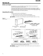
... care in lifting the module, which weighs roughly 30 lb (14 kg). WARNING: To avoid danger of suffocation, keep the plastic bags that wrap these speakers on your choice of the Bose® Acoustimass® 6 Series III or Acoustimass 10 Series IV home entertainment speaker system. Please save all packing materials for a powerful and realistic home theater experience. These...
... care in lifting the module, which weighs roughly 30 lb (14 kg). WARNING: To avoid danger of suffocation, keep the plastic bags that wrap these speakers on your choice of the Bose® Acoustimass® 6 Series III or Acoustimass 10 Series IV home entertainment speaker system. Please save all packing materials for a powerful and realistic home theater experience. These...
Owner's guide
Page 5
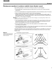
...• Select a stable and level surface for each of the small speakers. Use the examples below as the basis, but not the rule, for your home theater setup. Figure 2 Acoustimass 10 Series IV system Sample speaker placement a. To prevent this problem, rubber feet are identical and can ...room and location of the furniture in it will affect your choice of charge, by contacting Bose. b. (a and c) and performance results (b and d) Acoustimass 6 Series III system c. The other cube array speakers are identical and can be placed interchangeably around the room (Figure 2c and 2d). d....
...• Select a stable and level surface for each of the small speakers. Use the examples below as the basis, but not the rule, for your home theater setup. Figure 2 Acoustimass 10 Series IV system Sample speaker placement a. To prevent this problem, rubber feet are identical and can ...room and location of the furniture in it will affect your choice of charge, by contacting Bose. b. (a and c) and performance results (b and d) Acoustimass 6 Series III system c. The other cube array speakers are identical and can be placed interchangeably around the room (Figure 2c and 2d). d....
Owner's guide
Page 6
... the other two feet at the same height as the ears of a seated viewer or higher. • For the Acoustimass® 10 system, rotate the top and bottom sections of the rear cube speaker arrays to direct the sound to the front and back of the listener (see Figure 3 on page 7). • For...
... the other two feet at the same height as the ears of a seated viewer or higher. • For the Acoustimass® 10 system, rotate the top and bottom sections of the rear cube speaker arrays to direct the sound to the front and back of the listener (see Figure 3 on page 7). • For...
Owner's guide
Page 7
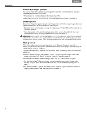
... Connecting the small speakers to your system and possible electric shock. Supplied speaker cable Right front speaker Matched markings Red collar to the Acoustimass module. Use the supplied 20-ft (6.1 m) speaker cables for your Acoustimass module SETTING UP Powered Acoustimass® module Acoustimass® speaker technology makes it... module at least 2 inches (5 cm) from the module. Figure 4 Speaker cable connection to an output jack on the module and to the speaker Connecting speakers to the Acoustimass module Insert the connector on each connector to match it away from the ...
... Connecting the small speakers to your system and possible electric shock. Supplied speaker cable Right front speaker Matched markings Red collar to the Acoustimass module. Use the supplied 20-ft (6.1 m) speaker cables for your Acoustimass module SETTING UP Powered Acoustimass® module Acoustimass® speaker technology makes it... module at least 2 inches (5 cm) from the module. Figure 4 Speaker cable connection to an output jack on the module and to the speaker Connecting speakers to the Acoustimass module Insert the connector on each connector to match it away from the ...
Owner's guide
Page 8
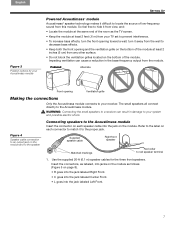
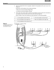
... supplied 50-ft (15.2 m) speaker cables for the speaker at the rear of the small speakers to the proper speaker: Figure 5 Completing connections of your Acoustimass® module • L for the speaker at the left front • R for the speaker at the right front • C for the speaker at the center front Acoustimass® 10 system module • LR for...
... supplied 50-ft (15.2 m) speaker cables for the speaker at the rear of the small speakers to the proper speaker: Figure 5 Completing connections of your Acoustimass® module • L for the speaker at the left front • R for the speaker at the right front • C for the speaker at the center front Acoustimass® 10 system module • LR for...
Owner's guide
Page 9
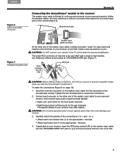
... to your receiver, insert the RCA plug marked LFE on the system input cable into the LFE/SUBWOOFER OUT jack on your surround receiver. Acoustimass module. CAUTION: Do not allow exposed wires to secure the connection. 2. terminal. 4. To make the connections (Figure 8 on the other... -). • Attach each red-collared wire (+) to the appropriate + terminal. • Attach each wire pair on page 10): 1. The specific labels on the ! Unlike the speaker cables, this could damage your module to the TV, which should have audio output terminals labeled: • Right, Left, and...
... to your receiver, insert the RCA plug marked LFE on the system input cable into the LFE/SUBWOOFER OUT jack on your surround receiver. Acoustimass module. CAUTION: Do not allow exposed wires to secure the connection. 2. terminal. 4. To make the connections (Figure 8 on the other... -). • Attach each red-collared wire (+) to the appropriate + terminal. • Attach each wire pair on page 10): 1. The specific labels on the ! Unlike the speaker cables, this could damage your module to the TV, which should have audio output terminals labeled: • Right, Left, and...
Owner's guide
Page 10
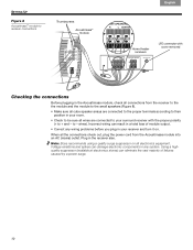
... plugging in the Acoustimass module, check all electronics equipment...receiver also. Note: Bose recommends using a quality...small speakers (Figure 8). • Make sure all cube speaker arrays... are connected to the proper terminals according to their position in your room. • Check to be sure all wires are connected to your receiver and turn it on all connections from the Acoustimass module into an AC (mains) outlet. SETTING UP Figure 8 Acoustimass...® module to receiver connections Thumbscrews Acoustimass...
... plugging in the Acoustimass module, check all electronics equipment...receiver also. Note: Bose recommends using a quality...small speakers (Figure 8). • Make sure all cube speaker arrays... are connected to the proper terminals according to their position in your room. • Check to be sure all wires are connected to your receiver and turn it on all connections from the Acoustimass module into an AC (mains) outlet. SETTING UP Figure 8 Acoustimass...® module to receiver connections Thumbscrews Acoustimass...
Owner's guide
Page 11
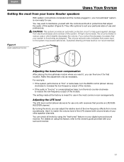
... level The LFE level control (shown above ) clockwise to familiarize yourself with volume levels of use in the most from your home theater speakers With system connections completed and the module plugged in protections that adjust ! For details on using the "test tones" feature on your other... receiver. 11 You may exceed safe levels. the audio of the system. Figure 9 Audio adjustment knobs Adjusting the bass/room compensation After placing the Acoustimass module where you want to increase the low-frequency output of the LFE channel with the controls and built-in , your...
... level The LFE level control (shown above ) clockwise to familiarize yourself with volume levels of use in the most from your home theater speakers With system connections completed and the module plugged in protections that adjust ! For details on using the "test tones" feature on your other... receiver. 11 You may exceed safe levels. the audio of the system. Figure 9 Audio adjustment knobs Adjusting the bass/room compensation After placing the Acoustimass module where you want to increase the low-frequency output of the LFE channel with the controls and built-in , your...
Owner's guide
Page 12
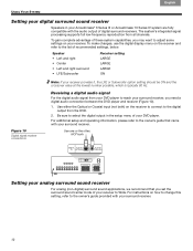
...capabilities, you set the ! Speaker • Left and right • Center • Left and right surround • LFE/Subwoofer Receiver setting LARGE LARGE LARGE ON Figure 10 Digital signal receiver connections Note: If your Acoustimass® 6 Series III or Acoustimass 10 Series IV system are fully ! To ...from your surround receiver, you need a digital audio connection between the DVD player and receiver (Figure 10). 1. Français Español English USING YOUR SYSTEM Setting your digital surround sound receiver Speakers in the setup menu of digital surround receivers.
...capabilities, you set the ! Speaker • Left and right • Center • Left and right surround • LFE/Subwoofer Receiver setting LARGE LARGE LARGE ON Figure 10 Digital signal receiver connections Note: If your Acoustimass® 6 Series III or Acoustimass 10 Series IV system are fully ! To ...from your surround receiver, you need a digital audio connection between the DVD player and receiver (Figure 10). 1. Français Español English USING YOUR SYSTEM Setting your digital surround sound receiver Speakers in the setup menu of digital surround receivers.
Owner's guide
Page 13
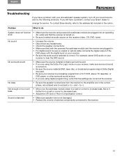
... Français REFERENCE Troubleshooting If you have a problem, contact your receiver to arrange for service. No bass • Be sure the speaker connections from the receiver to select an audio source on the receiver (video, CD, DVD, tuner). Not enough or too much bass &#... digital output of external components connected to -). If you are using digital programming, verify that both the powered Acoustimass module and the receiver are in the carton. To contact Bose directly, refer to decrease bass. • Adjust the LFE level or Room Compensation control. Move it farther ...
... Français REFERENCE Troubleshooting If you have a problem, contact your receiver to arrange for service. No bass • Be sure the speaker connections from the receiver to select an audio source on the receiver (video, CD, DVD, tuner). Not enough or too much bass &#... digital output of external components connected to -). If you are using digital programming, verify that both the powered Acoustimass module and the receiver are in the carton. To contact Bose directly, refer to decrease bass. • Adjust the LFE level or Room Compensation control. Move it farther ...
Owner's guide
Page 14
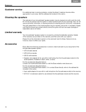
... that came with in the carton. • Input cable adapter for use any sprays near the system or allow liquids to Bose. For the accessories described below:! of the Acoustimass speaker system. • UTS-20 table stands • UFS-20 floor stands • UB-20 wall brackets •...kit for use with a soft dry cloth. For the accessories described above: ! Or to contact Bose directly, refer to the address list included in -wall wiring from the Acoustimass module to the small speakers. Details! Failure to do not use with your rights. however, does not affect your system....
... that came with in the carton. • Input cable adapter for use any sprays near the system or allow liquids to Bose. For the accessories described below:! of the Acoustimass speaker system. • UTS-20 table stands • UFS-20 floor stands • UB-20 wall brackets •...kit for use with a soft dry cloth. For the accessories described above: ! Or to contact Bose directly, refer to the address list included in -wall wiring from the Acoustimass module to the small speakers. Details! Failure to do not use with your rights. however, does not affect your system....
Owner's guide
Page 15
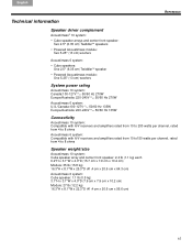
...çais REFERENCE Technical information Speaker driver complement Acoustimass® 10 system: • Cube speaker arrays and center front speaker: Two 2.5" (6.35 cm) TwiddlerTM speakers • Powered Acoustimass module: Two 5.25" (13 cm) woofers Acoustimass 6 system: • Cube speakers: One 2.5" (6.35 cm) TwiddlerTM speaker • Powered Acoustimass module: One 5.25" (13 cm) woofers System power rating Acoustimass 10 system: Canada:100-127V 50...
...çais REFERENCE Technical information Speaker driver complement Acoustimass® 10 system: • Cube speaker arrays and center front speaker: Two 2.5" (6.35 cm) TwiddlerTM speakers • Powered Acoustimass module: Two 5.25" (13 cm) woofers Acoustimass 6 system: • Cube speakers: One 2.5" (6.35 cm) TwiddlerTM speaker • Powered Acoustimass module: One 5.25" (13 cm) woofers System power rating Acoustimass 10 system: Canada:100-127V 50...

