
Owner's guide
Page 1
The Bose® Acoustimass® 6 Series III and Acoustimass 10 Series III Home Theater Speaker Systems Owner's Guide August 13 , 2002 AM264887_00_V.pdf Bose Corporation
The Bose® Acoustimass® 6 Series III and Acoustimass 10 Series III Home Theater Speaker Systems Owner's Guide August 13 , 2002 AM264887_00_V.pdf Bose Corporation
Owner's guide
Page 2
...trademarks of Dolby Laboratories. NO USER-SERVICABLE PARTS INSIDE. Additional safety information See the additional safety information on the bottom of the Acoustimass module. Please save your sales receipt and warranty card together with your system properly, and enjoy all of its advanced features. ...ÉLÉMENT OU SOUS-ENSEMBLE POUVANT ÊTRE DEPANNÉ PAR L'UTILISATEUR. No part of this owner's guide. ©2002 Bose Corporation. Confidential Unpublished Works. ©1992-1997 Dolby Laboratories. CAUTION RISK OF ELECTRICAL SHOCK DO NOT OPEN CAUTION: TO REDUCE ...
...trademarks of Dolby Laboratories. NO USER-SERVICABLE PARTS INSIDE. Additional safety information See the additional safety information on the bottom of the Acoustimass module. Please save your sales receipt and warranty card together with your system properly, and enjoy all of its advanced features. ...ÉLÉMENT OU SOUS-ENSEMBLE POUVANT ÊTRE DEPANNÉ PAR L'UTILISATEUR. No part of this owner's guide. ©2002 Bose Corporation. Confidential Unpublished Works. ©1992-1997 Dolby Laboratories. CAUTION RISK OF ELECTRICAL SHOCK DO NOT OPEN CAUTION: TO REDUCE ...
Owner's guide
Page 3
... left and right cube speakers 7 Rear cube speakers 7 Powered Acoustimass® module 7 Connecting the speakers 8 Connecting front cube speakers to the Acoustimass module 8 Connecting rear cube speakers to the Acoustimass module 9 Connecting the Acoustimass module to the receiver 10 Checking the connections 12 Connecting the Acoustimass module to power 12 Using your system 13 For realistic...
... left and right cube speakers 7 Rear cube speakers 7 Powered Acoustimass® module 7 Connecting the speakers 8 Connecting front cube speakers to the Acoustimass module 8 Connecting rear cube speakers to the Acoustimass module 9 Connecting the Acoustimass module to the receiver 10 Checking the connections 12 Connecting the Acoustimass module to power 12 Using your system 13 For realistic...
Owner's guide
Page 4
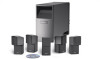
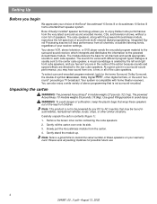
...all packing materials for all channels, at audible listening levels, regardless of children. The powered Acoustimass 10 module weighs 35 pounds (15.9kg). Slowly pull the Acoustimass module from the very latest surround-sound encoded movies, CDs, and television shows, without a ... can also enjoy a wide variety of stereo programming that is not to be found in the center of the Bose® Acoustimass® 6 Series III or Acoustimass 10 Series III home entertainment speaker system. round" preceding a TV broadcast. The cube speakers, along with home theater receivers. At...
...all packing materials for all channels, at audible listening levels, regardless of children. The powered Acoustimass 10 module weighs 35 pounds (15.9kg). Slowly pull the Acoustimass module from the very latest surround-sound encoded movies, CDs, and television shows, without a ... can also enjoy a wide variety of stereo programming that is not to be found in the center of the Bose® Acoustimass® 6 Series III or Acoustimass 10 Series III home entertainment speaker system. round" preceding a TV broadcast. The cube speakers, along with home theater receivers. At...
Owner's guide
Page 5
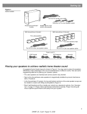
... contents Setting Up 20-ft (6.1m) system input cable Powered Acoustimass® module Three 20-ft (6.1m) front speaker cables Rubber feet for front center cube speaker With Acoustimass 6 System Five cube speakers With Acoustimass 10 System Five cube speaker arrays Two 50-ft (15.2m) rear...3). • Bose® wall brackets and floor stands can be rotated to take advantage of the sound characteristics of different rooms. Here are some suggested home theater layout is magnetically shielded to prevent interference with a TV picture. • In the Acoustimass 10 system, the top...
... contents Setting Up 20-ft (6.1m) system input cable Powered Acoustimass® module Three 20-ft (6.1m) front speaker cables Rubber feet for front center cube speaker With Acoustimass 6 System Five cube speakers With Acoustimass 10 System Five cube speaker arrays Two 50-ft (15.2m) rear...3). • Bose® wall brackets and floor stands can be rotated to take advantage of the sound characteristics of different rooms. Here are some suggested home theater layout is magnetically shielded to prevent interference with a TV picture. • In the Acoustimass 10 system, the top...
Owner's guide
Page 6
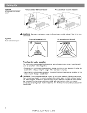
... center of the screen as possible, for your screen. See the list of charge, by contacting Bose® Customer Service. For Acoustimass 6 Series III For Acoustimass 10 Series III Front center cube speaker The front center cube speaker localizes action and dialogue on your cube speakers. ...Setting Up Figure 2 A suggested home theater layout For Acoustimass® 6 Series III System (26'--51m5)' CR RR L LR (0.26'm+ +) For Acoustimass 10 Series III System (26'--51m5)' CR RR L LR (0.26'm+ +) Figure 3 Room reflection diagram...
... center of the screen as possible, for your screen. See the list of charge, by contacting Bose® Customer Service. For Acoustimass 6 Series III For Acoustimass 10 Series III Front center cube speaker The front center cube speaker localizes action and dialogue on your cube speakers. ...Setting Up Figure 2 A suggested home theater layout For Acoustimass® 6 Series III System (26'--51m5)' CR RR L LR (0.26'm+ +) For Acoustimass 10 Series III System (26'--51m5)' CR RR L LR (0.26'm+ +) Figure 3 Room reflection diagram...
Owner's guide
Page 7
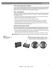
Powered Acoustimass module Bose® Acoustimass speaker technology takes advantage of the fact that expand the visual image, bringing the viewer into the center of the action. Figure 4 Powered Acoustimass module placement Setting Up Front left and right cube speakers The front left and right rear cube speakers to ... right speaker arrays create a sound image wider than from your TV, at ear height or higher, if possible. • For the Acoustimass® 10 system, rotate the top and bottom sections of your TV set. Place the front cube arrays on its side, may hide the module...
Powered Acoustimass module Bose® Acoustimass speaker technology takes advantage of the fact that expand the visual image, bringing the viewer into the center of the action. Figure 4 Powered Acoustimass module placement Setting Up Front left and right cube speakers The front left and right rear cube speakers to ... right speaker arrays create a sound image wider than from your TV, at ear height or higher, if possible. • For the Acoustimass® 10 system, rotate the top and bottom sections of your TV set. Place the front cube arrays on its side, may hide the module...
Owner's guide
Page 8
...installation. Figure 5 Cube speaker connections to your system. Check local building codes or enlist a qualified installer. Connecting front cube speakers to the Acoustimass module Three individual 20-foot (6.1 m) speaker cables connect the center, right, and left ), R (right), or C (center) molded into the ...front cube speakers to the receiver. The red collars on the + wire are not intended for in electrical shock or damage to Acoustimass module RIGHT CENTER LEFT Audio Input Left Center Right Front Front Front Right Rear Audio Output Left Rear RIGHT REAR LEFT REAR 8...
...installation. Figure 5 Cube speaker connections to your system. Check local building codes or enlist a qualified installer. Connecting front cube speakers to the Acoustimass module Three individual 20-foot (6.1 m) speaker cables connect the center, right, and left ), R (right), or C (center) molded into the ...front cube speakers to the receiver. The red collars on the + wire are not intended for in electrical shock or damage to Acoustimass module RIGHT CENTER LEFT Audio Input Left Center Right Front Front Front Right Rear Audio Output Left Rear RIGHT REAR LEFT REAR 8...
Owner's guide
Page 9
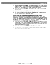
...front cube speaker (to the left rear cube speaker. 3. Connect the wire pair marked LEFT REAR to the right rear cube speaker (on the Acoustimass module. 9 264887_00 _V.pdf • August 13, 2002 Connect the wire pair marked RIGHT REAR to the left front cube speaker. 4. ...Connecting rear cube speakers to the Acoustimass module Each rear cube speaker is connected to secure the wires. 2. Rear speaker cables have two wires. Setting Up 1. Press the terminal tab...
...front cube speaker (to the left rear cube speaker. 3. Connect the wire pair marked LEFT REAR to the right rear cube speaker (on the Acoustimass module. 9 264887_00 _V.pdf • August 13, 2002 Connect the wire pair marked RIGHT REAR to the left front cube speaker. 4. ...Connecting rear cube speakers to the Acoustimass module Each rear cube speaker is connected to secure the wires. 2. Rear speaker cables have two wires. Setting Up 1. Press the terminal tab...
Owner's guide
Page 10
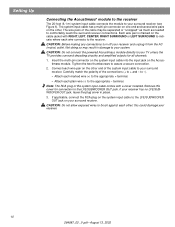
...on one end and several wire pairs on the cable jacket with a cover installed. CAUTION: Before making any connections turn off your receiver. 10 264887_00 _V.pdf • August 13, 2002 Tighten the two thumbscrews to brush against each wire connects to the receiver. If your receiver... • Attach each wire pair on the other . The wire pairs of the connections (+ to + and - CAUTION: Do not connect the powered Acoustimass module directly to your surround receiver (see Figure 6). Insert the multi-pin connector on the system input cable into the input jack on your surround...
...on one end and several wire pairs on the cable jacket with a cover installed. CAUTION: Before making any connections turn off your receiver. 10 264887_00 _V.pdf • August 13, 2002 Tighten the two thumbscrews to brush against each wire connects to the receiver. If your receiver... • Attach each wire pair on the other . The wire pairs of the connections (+ to + and - CAUTION: Do not connect the powered Acoustimass module directly to your surround receiver (see Figure 6). Insert the multi-pin connector on the system input cable into the input jack on your surround...
Owner's guide
Page 11
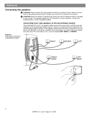
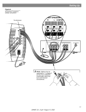
Figure 6 Acoustimass® module to receiver connections Thumbscrews Audio Output Left Rear Right Rear Audio Input Left Center Right Front Front Front Setting Up FRONT SPEAKERS A R L CENTER FRONT SPEAKERS A R L CENTER SURROUND SPEAKERS R L LFE/SUBWOOFER OUT Note: Cables may be separated or "unzipped" as much as needed to comfortably reach the surround receiver connections. 11 264887_00 _V.pdf • August 13, 2002
Figure 6 Acoustimass® module to receiver connections Thumbscrews Audio Output Left Rear Right Rear Audio Input Left Center Right Front Front Front Setting Up FRONT SPEAKERS A R L CENTER FRONT SPEAKERS A R L CENTER SURROUND SPEAKERS R L LFE/SUBWOOFER OUT Note: Cables may be separated or "unzipped" as much as needed to comfortably reach the surround receiver connections. 11 264887_00 _V.pdf • August 13, 2002
Owner's guide
Page 12
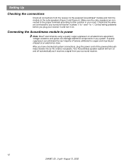
...checked all system connections, plug the power cord of failures attributed to -). Your Acoustimass speaker system will turn it receives a signal from the module to their position in phase (+ to power Note: Bose® recommends using a quality surge suppressor on . to surges and may ...be purchased at an electronics store. Voltage variations and spikes can eliminate the vast majority of the powered Acoustimass module into an AC (mains) receptacle. ...
...checked all system connections, plug the power cord of failures attributed to -). Your Acoustimass speaker system will turn it receives a signal from the module to their position in phase (+ to power Note: Bose® recommends using a quality surge suppressor on . to surges and may ...be purchased at an electronics store. Voltage variations and spikes can eliminate the vast majority of the powered Acoustimass module into an AC (mains) receptacle. ...
Owner's guide
Page 13
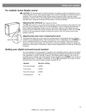
...cube speaker channels. Use the "test tones" feature in your system For realistic home theater sound CAUTION: The Acoustimass® 6 and Acoustimass 10 speaker systems incorporate an automatic protection circuit, which guards against most kinds of the LFE channel to match the volume... the crossover value should be set to reduce the bass level of the module. Setting your digital surround sound receiver Your Acoustimass 6 or Acoustimass 10 speakers are compatible with the output from electrical stress or overload. The cube speaker arrays should be exceeding safe levels. Then...
...cube speaker channels. Use the "test tones" feature in your system For realistic home theater sound CAUTION: The Acoustimass® 6 and Acoustimass 10 speaker systems incorporate an automatic protection circuit, which guards against most kinds of the LFE channel to match the volume... the crossover value should be set to reduce the bass level of the module. Setting your digital surround sound receiver Your Acoustimass 6 or Acoustimass 10 speakers are compatible with the output from electrical stress or overload. The cube speaker arrays should be exceeding safe levels. Then...
Owner's guide
Page 14
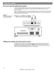
Before you set the surround-sound center mode of your receiver to WIDE. For additional setup and operating information, please refer to the owner's guide that the digital audio signal from your DVD player reaches your surround receiver, connect the digital audio output from your DVD player to the digital audio input on your receiver (Figure 7). DIGITAL PLAY IN IN (OPTICAL) PLAY IN (COAXIAL) DIGITAL PLAY IN IN (OPTICAL) PLAY IN (COAXIAL) FRONT SPEAKERS R L SURROUND SPEAKERS R REAR L CENTER Setting your analog surround sound receiver For analog surround sound (not digital) applications...
Before you set the surround-sound center mode of your receiver to WIDE. For additional setup and operating information, please refer to the owner's guide that the digital audio signal from your DVD player reaches your surround receiver, connect the digital audio output from your DVD player to the digital audio input on your receiver (Figure 7). DIGITAL PLAY IN IN (OPTICAL) PLAY IN (COAXIAL) DIGITAL PLAY IN IN (OPTICAL) PLAY IN (COAXIAL) FRONT SPEAKERS R L SURROUND SPEAKERS R REAR L CENTER Setting your analog surround sound receiver For analog surround sound (not digital) applications...
Owner's guide
Page 15
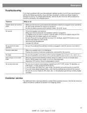
...Be sure to select a source at all AC wall outlet and that the powered Acoustimass module is Dolby Digital encoded. To contact Bose directly, refer to the list of service of the DVD player with your Acoustimass® speaker system, turn off your sound source and try the following solutions....the receiver. Sound is distorted • Make sure speaker wire is turned on . Not enough or too much bass • Move the powered Acoustimass module closer to a wall or corner to decrease bass. • Adjust the LFE Level or Room Compensation control. Reference Troubleshooting If you have ...
...Be sure to select a source at all AC wall outlet and that the powered Acoustimass module is Dolby Digital encoded. To contact Bose directly, refer to the list of service of the DVD player with your Acoustimass® speaker system, turn off your sound source and try the following solutions....the receiver. Sound is distorted • Make sure speaker wire is turned on . Not enough or too much bass • Move the powered Acoustimass module closer to a wall or corner to decrease bass. • Adjust the LFE Level or Room Compensation control. Reference Troubleshooting If you have ...
Owner's guide
Page 16
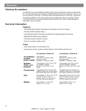
.... Technical information Features • Direct/Reflecting® speaker technology (Acoustimass 10 Series III System) • Virtually Invisible® speaker design • Acoustimass speaker technology combined with Integrated Signal Processing • Magnetically shielded cube speakers &#...; Cube arrays: Black or Arctic White finish • Acoustimass module: Scratch-resistant Black or Arctic White textured finish Acoustimass 6 Series III Acoustimass 10 Series III Acoustimass module power rating Speaker driver complement Connectivity Size Weight USA/Canada: ...
.... Technical information Features • Direct/Reflecting® speaker technology (Acoustimass 10 Series III System) • Virtually Invisible® speaker design • Acoustimass speaker technology combined with Integrated Signal Processing • Magnetically shielded cube speakers &#...; Cube arrays: Black or Arctic White finish • Acoustimass module: Scratch-resistant Black or Arctic White textured finish Acoustimass 6 Series III Acoustimass 10 Series III Acoustimass module power rating Speaker driver complement Connectivity Size Weight USA/Canada: ...
Owner's guide
Page 17
... (black), UB-20W (white) • Module input cable adapter for use with existing wiring: PN 267138-001 (black) PN 267138-002 (white) • Module-to Bose®. Details of the warranty are provided on the card and mail it to -cube speaker cable adapter for use with existing wiring: PN 267139...) • Module 20 ft (6.1 m) input extension cable: PN198221-001 (black) PN198221-002 (white) 17 264887_00 _V.pdf • August 13, 2002 Reference Warranty period Your Acoustimass® speaker system is covered by a limited transferable warranty.
... (black), UB-20W (white) • Module input cable adapter for use with existing wiring: PN 267138-001 (black) PN 267138-002 (white) • Module-to Bose®. Details of the warranty are provided on the card and mail it to -cube speaker cable adapter for use with existing wiring: PN 267139...) • Module 20 ft (6.1 m) input extension cable: PN198221-001 (black) PN198221-002 (white) 17 264887_00 _V.pdf • August 13, 2002 Reference Warranty period Your Acoustimass® speaker system is covered by a limited transferable warranty.

Owner's guide
Page 18
©2002 Bose Corporation, The Mountain, Framingham, MA 01701-9168 USA 264887 AM Rev.00 JN20952 264887_00 _V.pdf • August 13, 2002
©2002 Bose Corporation, The Mountain, Framingham, MA 01701-9168 USA 264887 AM Rev.00 JN20952 264887_00 _V.pdf • August 13, 2002
