User Manual
Page 2
... of important operating and maintenance instructions in this owner's guide. CAUTION: No naked flame sources, such as marked on the Acoustimass module: The lightning flash with arrowhead symbol within an equilateral triangle is located on the apparatus. Manufactured under license from Dolby Laboratories...safety information See the additional safety information on the Important Safety Instructions page enclosed with this owner's guide. ©2006 Bose Corporation. Serial number Dealer name Dealer phone Purchase date Please keep your sales receipt and warranty card together with your ...
... of important operating and maintenance instructions in this owner's guide. CAUTION: No naked flame sources, such as marked on the Acoustimass module: The lightning flash with arrowhead symbol within an equilateral triangle is located on the apparatus. Manufactured under license from Dolby Laboratories...safety information See the additional safety information on the Important Safety Instructions page enclosed with this owner's guide. ©2006 Bose Corporation. Serial number Dealer name Dealer phone Purchase date Please keep your sales receipt and warranty card together with your ...
User Manual
Page 3
... 4 Placing your speakers to achieve realistic home theater sound 5 Front left and right speakers 6 Center speaker 6 Rear speakers 6 Powered Acoustimass® module 7 Making the connections 7 Connecting speakers to the Acoustimass module 7 Connecting the Acoustimass module to the receiver 9 Checking the connections 10 USING YOUR SYSTEM 11 Getting the most from your home theater...
... 4 Placing your speakers to achieve realistic home theater sound 5 Front left and right speakers 6 Center speaker 6 Rear speakers 6 Powered Acoustimass® module 7 Making the connections 7 Connecting speakers to the Acoustimass module 7 Connecting the Acoustimass module to the receiver 9 Checking the connections 10 USING YOUR SYSTEM 11 Getting the most from your home theater...
User Manual
Page 4
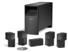
... to record the serial number of these speakers out of the reach of children. 4 These speakers, together with the Acoustimass module, reproduce the full spectrum of the Bose® Acoustimass® 6 Series III or Acoustimass 10 Series IV home entertainment speaker system. Please save all packing materials for a powerful and realistic home theater experience...
... to record the serial number of these speakers out of the reach of children. 4 These speakers, together with the Acoustimass module, reproduce the full spectrum of the Bose® Acoustimass® 6 Series III or Acoustimass 10 Series IV home entertainment speaker system. Please save all packing materials for a powerful and realistic home theater experience...
User Manual
Page 5
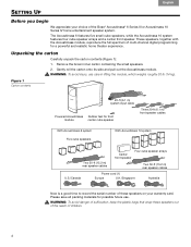
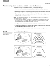
... surface for each cube array speaker can cause them to move, particularly on each of the small speakers. Figure 2 Acoustimass 10 Series IV system Sample speaker placement a. d. 5 Refer to the address list included in it will affect your ...cube on smooth surfaces like marble, glass, or highly polished wood. b. (a and c) and performance results (b and d) Acoustimass 6 Series III system c. English Español Français SETTING UP Placing your speakers to achieve realistic home theater sound...: You may order additional rubber feet, free of charge, by contacting Bose.
... surface for each cube array speaker can cause them to move, particularly on each of the small speakers. Figure 2 Acoustimass 10 Series IV system Sample speaker placement a. d. 5 Refer to the address list included in it will affect your ...cube on smooth surfaces like marble, glass, or highly polished wood. b. (a and c) and performance results (b and d) Acoustimass 6 Series III system c. English Español Français SETTING UP Placing your speakers to achieve realistic home theater sound...: You may order additional rubber feet, free of charge, by contacting Bose.
User Manual
Page 6
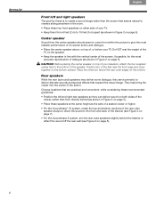
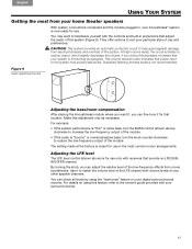
... above, on the bottom surface. Place the other two feet at the same height as the ears of a seated viewer or higher. • For the Acoustimass® 10 system, rotate the top and bottom sections of the rear cube speaker arrays to direct the sound to the front and back of... speaker should seem to come from within the picture to give the most accurate reproduction of the listener (see Figure 3 on page 7). • For the Acoustimass 6 system, aim the rear cube speakers slightly behind the listener or reflect the sound off the rear wall (see Figure 2 on page 5). 6 Position two of...
... above, on the bottom surface. Place the other two feet at the same height as the ears of a seated viewer or higher. • For the Acoustimass® 10 system, rotate the top and bottom sections of the rear cube speaker arrays to direct the sound to the front and back of... speaker should seem to come from within the picture to give the most accurate reproduction of the listener (see Figure 3 on page 7). • For the Acoustimass 6 system, aim the rear cube speakers slightly behind the listener or reflect the sound off the rear wall (see Figure 2 on page 5). 6 Position two of...
User Manual
Page 7
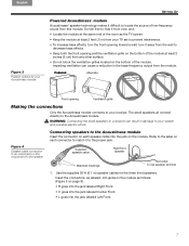
... Keep the module at least 2 feet (.6 m) from the module. Use the supplied 20-ft (6.1 m) speaker cables for your Acoustimass module SETTING UP Powered Acoustimass® module Acoustimass® speaker technology makes it to the proper jack. Impeding ventilation can result in the bass-frequency output from your TV set...turn the front opening and the ventilation grille on the module. So feel free to hide it away from the wall to the Acoustimass module Insert the connector on each connector to match it difficult to locate the source of low-frequency sound from any other surface. ...
... Keep the module at least 2 feet (.6 m) from the module. Use the supplied 20-ft (6.1 m) speaker cables for your Acoustimass module SETTING UP Powered Acoustimass® module Acoustimass® speaker technology makes it to the proper jack. Impeding ventilation can result in the bass-frequency output from your TV set...turn the front opening and the ventilation grille on the module. So feel free to hide it away from the wall to the Acoustimass module Insert the connector on each connector to match it difficult to locate the source of low-frequency sound from any other surface. ...
User Manual
Page 8
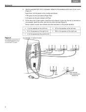
... Left Rear. 3. Insert them into the other end of each red-collared wire that matches it to the proper speaker: Figure 5 Completing connections of your Acoustimass® module • L for the speaker at the left front • R for the speaker at the right front • C for the speaker at the ...center front Acoustimass® 10 system module • LR for the speaker at the left rear • RR for the speakers at the right rear Right front speaker...
... Left Rear. 3. Insert them into the other end of each red-collared wire that matches it to the proper speaker: Figure 5 Completing connections of your Acoustimass® module • L for the speaker at the left front • R for the speaker at the right front • C for the speaker at the ...center front Acoustimass® 10 system module • LR for the speaker at the left rear • RR for the speakers at the right rear Right front speaker...

User Manual
Page 9
... the input jack on your receiver, insert the RCA plug marked LFE on the system input cable into terminals on the module (Figure 6). Acoustimass module. The specific labels on page 10): 1. English Español Français SETTING UP Figure 6 System input cable connection Connecting the... Acoustimass® module to the receiver The system input cable is for use ONLY with a receiver that handles ! Unlike the speaker cables, this could ...
... the input jack on your receiver, insert the RCA plug marked LFE on the system input cable into terminals on the module (Figure 6). Acoustimass module. The specific labels on page 10): 1. English Español Français SETTING UP Figure 6 System input cable connection Connecting the... Acoustimass® module to the receiver The system input cable is for use ONLY with a receiver that handles ! Unlike the speaker cables, this could ...
User Manual
Page 10
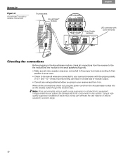
...highquality suppressor (available at electronics stores) can damage electronic components in the receiver also. SETTING UP Figure 8 Acoustimass® module to receiver connections Thumbscrews Acoustimass® module Français Español English Home theater receivers LFE connector with the proper polarity ... receiver with cover removed Checking the connections Before plugging in the Acoustimass module, check all connections from the Acoustimass module into an AC (mains) outlet. to + and - Note: Bose recommends using a quality surge suppressor on all wires are connected ...
...highquality suppressor (available at electronics stores) can damage electronic components in the receiver also. SETTING UP Figure 8 Acoustimass® module to receiver connections Thumbscrews Acoustimass® module Français Español English Home theater receivers LFE connector with the proper polarity ... receiver with cover removed Checking the connections Before plugging in the Acoustimass module, check all connections from the Acoustimass module into an AC (mains) outlet. to + and - Note: Bose recommends using a quality surge suppressor on all wires are connected ...
User Manual
Page 11
... and the module plugged in protections that ! If you notice this system (Figure 9). Figure 9 Audio adjustment knobs Adjusting the bass/room compensation After placing the Acoustimass module where you want to match the volume level of the LFE channel with receivers that your particular style of your... Acoustimass® system is now ready for use . For example: • If the system performance is "boomy" or overemphasizes bass, turn the BASS control (shown above ) ...
... and the module plugged in protections that ! If you notice this system (Figure 9). Figure 9 Audio adjustment knobs Adjusting the bass/room compensation After placing the Acoustimass module where you want to match the volume level of the LFE channel with receivers that your particular style of your... Acoustimass® system is now ready for use . For example: • If the system performance is "boomy" or overemphasizes bass, turn the BASS control (shown above ) ...
User Manual
Page 12
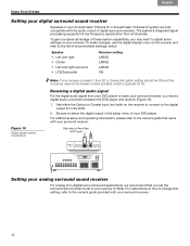
...-digital) surround sound applications, we recommend that came with the audio output of your surround receiver. Be sure to the list of your Acoustimass® 6 Series III or Acoustimass 10 Series IV system are fully ! settings on the receiver and refer to select the digital output in your DVD player. Use one...
...-digital) surround sound applications, we recommend that came with the audio output of your surround receiver. Be sure to the list of your Acoustimass® 6 Series III or Acoustimass 10 Series IV system are fully ! settings on the receiver and refer to select the digital output in your DVD player. Use one...
User Manual
Page 13
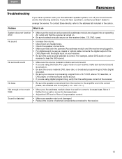
..., laserdisc, or DVD player, or other surround sound source. • If you are correct at all AC outlet and that both the powered Acoustimass module and the receiver are plugged in. • For digital sound, be sure a coaxial or optical cable connects the digital output of external ...and - Move it farther from the receiver to the amplifier are plugged into an operating at the receiver. If you have a problem, contact your Bose® dealer to -). Problem What to hear the DVD sound. English Español Français REFERENCE Troubleshooting If you still have a ...
..., laserdisc, or DVD player, or other surround sound source. • If you are correct at all AC outlet and that both the powered Acoustimass module and the receiver are plugged in. • For digital sound, be sure a coaxial or optical cable connects the digital output of external ...and - Move it farther from the receiver to the amplifier are plugged into an operating at the receiver. If you have a problem, contact your Bose® dealer to -). Problem What to hear the DVD sound. English Español Français REFERENCE Troubleshooting If you still have a ...
User Manual
Page 14
...with your rights. Details! appropriate to spill into any sprays near the system or allow liquids to your authorized Bose dealer. Cleaning the speakers The cabinets of the Acoustimass speaker system. • UTS-20 table stands • UFS-20 floor stands • UB-20 wall brackets... • Speaker wire adapter kit for use with in-wall wiring from the Acoustimass module to Bose. Limited warranty Your Acoustimass® speaker system is not taken. Do not use any solvents, chemicals, or cleaning solutions containing alcohol, ammonia, or ...
...with your rights. Details! appropriate to spill into any sprays near the system or allow liquids to your authorized Bose dealer. Cleaning the speakers The cabinets of the Acoustimass speaker system. • UTS-20 table stands • UFS-20 floor stands • UB-20 wall brackets... • Speaker wire adapter kit for use with in-wall wiring from the Acoustimass module to Bose. Limited warranty Your Acoustimass® speaker system is not taken. Do not use any solvents, chemicals, or cleaning solutions containing alcohol, ammonia, or ...
User Manual
Page 15
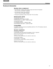
... (1.1 kg) each! 6.2"H x 3.1"W x 4.0"D (15.7 cm x 7.9 cm x 10.2 cm) Module: 35 lb (15.8 kg)! 16.3"H x 8.1"W x 25.3"D (41.4 cm x 20.6 cm x 64.3 cm) Acoustimass 6 system: Cube speaker: 1.1 lb (0.5 kg)! 3.1"H x 3.1"W x 4.0"D (7.9 cm x 7.9 cm x 10.2 cm) Module: 27 lb (12.2 kg)! 16.3"H x 8.1"W x 22.3"D (41.4 cm x 20.6 cm... x 56.6 cm) 15 Europe/Australia: 220-240V 50/60 Hz 270W Acoustimass 6 system:! Europe/Australia: 220-240V 50/60 Hz 135W Compatibility Compatible with A/V receivers and amplifiers rated from 4 to 150 watts per channel, ! Canada...
... (1.1 kg) each! 6.2"H x 3.1"W x 4.0"D (15.7 cm x 7.9 cm x 10.2 cm) Module: 35 lb (15.8 kg)! 16.3"H x 8.1"W x 25.3"D (41.4 cm x 20.6 cm x 64.3 cm) Acoustimass 6 system: Cube speaker: 1.1 lb (0.5 kg)! 3.1"H x 3.1"W x 4.0"D (7.9 cm x 7.9 cm x 10.2 cm) Module: 27 lb (12.2 kg)! 16.3"H x 8.1"W x 22.3"D (41.4 cm x 20.6 cm... x 56.6 cm) 15 Europe/Australia: 220-240V 50/60 Hz 270W Acoustimass 6 system:! Europe/Australia: 220-240V 50/60 Hz 135W Compatibility Compatible with A/V receivers and amplifiers rated from 4 to 150 watts per channel, ! Canada...
