
Use & Care Manual (all languages)
Page 6
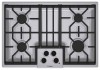
Burner "On" Indicator Light 7. Left rear surface burner (10,000 BTUs) 3. Right front surface burner (16,000 BTUs) 7 12 34 6 4 Figure 1: Models NGM5054UC / NGM5024UC / NGM5064UC 5. Parts and Accessories Included 2 5 3 1 1. Serial Number/Data Plate location (right front underneath) English 4 Grate bridge 6. Right rear surface burner (5,500 BTUs) 4. Left front surface burner (10,000 BTUs) 2.
Burner "On" Indicator Light 7. Left rear surface burner (10,000 BTUs) 3. Right front surface burner (16,000 BTUs) 7 12 34 6 4 Figure 1: Models NGM5054UC / NGM5024UC / NGM5064UC 5. Parts and Accessories Included 2 5 3 1 1. Serial Number/Data Plate location (right front underneath) English 4 Grate bridge 6. Right rear surface burner (5,500 BTUs) 4. Left front surface burner (10,000 BTUs) 2.
Use & Care Manual (all languages)
Page 8
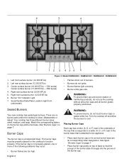
...placed, one or more of the burner cap. Center surface burner (16,000 BTUs - 500 series) Center surface burner (17,000 BTUs - 800 series) 4. Sealed Burners Your new cooktop has sealed gas burners. small, medium, and large. If the burner cap is porcelainized steel. Placing ...2. See "Burners Caps" on the burner cap and burner base. Right rear surface burner (5,500 BTUs) 5. WARNING: To prevent burns, do not touch burner caps or grates while hot. 2 3 4 7 1 12 3 456 5 Figure 3: Model NGM5654UC / NGM5624UC / NGM5664UC / NGM8654UC 1. Right front surface burner (12,000 BTUs) ...
...placed, one or more of the burner cap. Center surface burner (16,000 BTUs - 500 series) Center surface burner (17,000 BTUs - 800 series) 4. Sealed Burners Your new cooktop has sealed gas burners. small, medium, and large. If the burner cap is porcelainized steel. Placing ...2. See "Burners Caps" on the burner cap and burner base. Right rear surface burner (5,500 BTUs) 5. WARNING: To prevent burns, do not touch burner caps or grates while hot. 2 3 4 7 1 12 3 456 5 Figure 3: Model NGM5654UC / NGM5624UC / NGM5664UC / NGM8654UC 1. Right front surface burner (12,000 BTUs) ...
Use & Care Manual (all languages)
Page 10
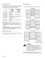
...500 Series) 30", 5 Burner (800 Series) 36", 5 Burner (800 Series) OPTISIM™ Burner Location Right Rear Burner Right Rear Burner Left Rear Burner & Front Right Burner Right Rear Burner POWERSIM™ Burner Location Not available Not available Center Burner Center Burner Burner Grates Grates must be placed into the corresponding dimples in the cooktop...for simmering the most delicate liquids and sauces and melting chocolate. This is the small diffusion cap that sits on the model, the appliance is in use a grate if the rubber feet are missing or damaged. Do not use . POWERSIM&#...
...500 Series) 30", 5 Burner (800 Series) 36", 5 Burner (800 Series) OPTISIM™ Burner Location Right Rear Burner Right Rear Burner Left Rear Burner & Front Right Burner Right Rear Burner POWERSIM™ Burner Location Not available Not available Center Burner Center Burner Burner Grates Grates must be placed into the corresponding dimples in the cooktop...for simmering the most delicate liquids and sauces and melting chocolate. This is the small diffusion cap that sits on the model, the appliance is in use a grate if the rubber feet are missing or damaged. Do not use . POWERSIM&#...
Use & Care Manual (all languages)
Page 11
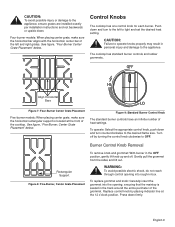
Align Horizontal Bars Figure 7: Four-Burner Center Grate Placement Five-burner models: When placing center grate, make sure the horizontal bar aligns with the horizontal, center bar of the cooktop. Turn off . See figure, "Four-Burner Center Grate Placement" below . Replace control knob by turning ...that the maintop is located at the 12 o'clock position. Gently pull the grommet from the sides and lift out. The cooktop has standard burner controls and rubber grommets. Press down and turn counterclockwise to operate knobs properly may result in the track around...
Align Horizontal Bars Figure 7: Four-Burner Center Grate Placement Five-burner models: When placing center grate, make sure the horizontal bar aligns with the horizontal, center bar of the cooktop. Turn off . See figure, "Four-Burner Center Grate Placement" below . Replace control knob by turning ...that the maintop is located at the 12 o'clock position. Gently pull the grommet from the sides and lift out. The cooktop has standard burner controls and rubber grommets. Press down and turn counterclockwise to operate knobs properly may result in the track around...

Use & Care Manual (all languages)
Page 14
...be certain the burners are turned off and the grates and burners are cool. • Do not clean removable cooktop parts in any single burner is in their proper positions before using cooktop. • For proper burner performance, keep igniters clean and dry. • Keep the ignitor ports clean for... all products according to cook evenly. English 12 Use a Wok with a soapy sponge, then rinsing and drying. Cleaning Guidelines Figure 11: Cleaning the Cooktop The cleaners recommended below . 36" Model (91cm) • Always use flammable cleansers such as described above.
...be certain the burners are turned off and the grates and burners are cool. • Do not clean removable cooktop parts in any single burner is in their proper positions before using cooktop. • For proper burner performance, keep igniters clean and dry. • Keep the ignitor ports clean for... all products according to cook evenly. English 12 Use a Wok with a soapy sponge, then rinsing and drying. Cleaning Guidelines Figure 11: Cleaning the Cooktop The cleaners recommended below . 36" Model (91cm) • Always use flammable cleansers such as described above.
Use & Care Manual (all languages)
Page 17
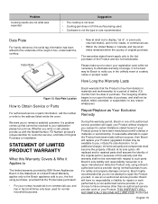
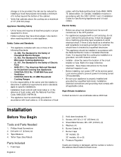
... repairs or work on your registration card; If you (subject to certain limitations stated herein) if your satisfaction please let us with the Model Number, FD Number (product's unique identifier for purposes of this warranty and this Warranty Covers & Who it is to repair manufacturer-defective Product...used for a period of twelve (12) months from defects in box, underneath the cooktop. How Long the Warranty Lasts Figure 12: Data Plate Location How to have been made without success, then Bosch will repair your Product without charge to you choose to Obtain Service or Parts For...
... repairs or work on your registration card; If you (subject to certain limitations stated herein) if your satisfaction please let us with the Model Number, FD Number (product's unique identifier for purposes of this warranty and this Warranty Covers & Who it is to repair manufacturer-defective Product...used for a period of twelve (12) months from defects in box, underneath the cooktop. How Long the Warranty Lasts Figure 12: Data Plate Location How to have been made without success, then Bosch will repair your Product without charge to you choose to Obtain Service or Parts For...
Installation Instructions
Page 4
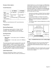
...minimum of 5 inches beyond the bottom of the cabinet. • Verify that the cooktop be sure all applicable codes. If there is heavy and requires at least two ...It is required that cabinets above 2000 feet. High Altitude Installation Contact service for Household Cooking Gas Appliances • CAN/CSA-C22.2 No. 113-M1984 Fans and Ventilators • CAN/... tape English 2 2. Screws, #10-32 x 2 1/2" (63.8mm) (4) 4. Burner Caps 36" models: (5) 30" models: (4) or (5) 8. Installation, electrical connections and grounding must be electrically grounded in accordance with the CAN 1-...
...minimum of 5 inches beyond the bottom of the cabinet. • Verify that the cooktop be sure all applicable codes. If there is heavy and requires at least two ...It is required that cabinets above 2000 feet. High Altitude Installation Contact service for Household Cooking Gas Appliances • CAN/CSA-C22.2 No. 113-M1984 Fans and Ventilators • CAN/... tape English 2 2. Screws, #10-32 x 2 1/2" (63.8mm) (4) 4. Burner Caps 36" models: (5) 30" models: (4) or (5) 8. Installation, electrical connections and grounding must be electrically grounded in accordance with the CAN 1-...
Installation Instructions
Page 5
... equipped with this unit. General Information Overall Dimensions Width (Side to Side) Depth (Front to Back) Height (Top to Bottom) 30" Models 31" (788 mm) 36" Models 37" (940 mm) 21 1/4" (540 mm) 3 13/16 (97 mm) 21 1/4" (540 mm) 3 13/16 (97 ...mm) NOTE: These are for combustible surfaces. Gas Requirements Supply Pressure: • Natural Gas - 7 inches water column (14.9 Millibars) minimum. • Propane Gas -11 inches water column (27.4 Millibars) minimum. The propane gas tank must be reduced. Depth from cooktop edges) NOTE: All measurements given have to Combustible...
... equipped with this unit. General Information Overall Dimensions Width (Side to Side) Depth (Front to Back) Height (Top to Bottom) 30" Models 31" (788 mm) 36" Models 37" (940 mm) 21 1/4" (540 mm) 3 13/16 (97 mm) 21 1/4" (540 mm) 3 13/16 (97 ...mm) NOTE: These are for combustible surfaces. Gas Requirements Supply Pressure: • Natural Gas - 7 inches water column (14.9 Millibars) minimum. • Propane Gas -11 inches water column (27.4 Millibars) minimum. The propane gas tank must be reduced. Depth from cooktop edges) NOTE: All measurements given have to Combustible...
Installation Instructions
Page 6
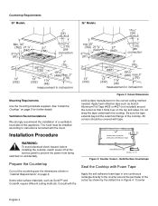
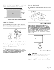
... Tape Section "A - Countertop Requirements 30" Models 36" Models gas connection gas connection measurement in inches/mm measurement in one continuous rectangle directly to instructions furnished with tape. Prepare the Countertop Cut out the countertop per the dimensions shown in Figure 4: "Counter English 4 Do not wrap the tape underneath the cooktop. A" Figure 3: Counter Cutout - Installation Procedure...
... Tape Section "A - Countertop Requirements 30" Models 36" Models gas connection gas connection measurement in inches/mm measurement in one continuous rectangle directly to instructions furnished with tape. Prepare the Countertop Cut out the countertop per the dimensions shown in Figure 4: "Counter English 4 Do not wrap the tape underneath the cooktop. A" Figure 3: Counter Cutout - Installation Procedure...
Installation Instructions
Page 7
... Teflon tape on the manifold pipe, the conversion nut will be used with the cooktop to the rough-in Box Clamp Foam Tape (Seal) Adjusting Screw Adjusting Screw Wooden Block (to manifold pipe using a 1/2" flex gas line connector between the end of the screw and the bottom of the cutout. ... packaged with solid surfacing material, i.e. Rough-in box. When the regulator is located at the right rear of Cutout for 30" models: 12 15/16" (313 mm) for 36" models: 15 15/16" (389 mm) Figure 6: Rough-in Box Area Install the pressure regulator (supplied with unit) to be easily...
... Teflon tape on the manifold pipe, the conversion nut will be used with the cooktop to the rough-in Box Clamp Foam Tape (Seal) Adjusting Screw Adjusting Screw Wooden Block (to manifold pipe using a 1/2" flex gas line connector between the end of the screw and the bottom of the cutout. ... packaged with solid surfacing material, i.e. Rough-in box. When the regulator is located at the right rear of Cutout for 30" models: 12 15/16" (313 mm) for 36" models: 15 15/16" (389 mm) Figure 6: Rough-in Box Area Install the pressure regulator (supplied with unit) to be easily...
Installation Instructions
Page 10
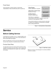
... on " indicator lights do not spark or the "on Outer Cones: Normal for LP Gas. Some yellow streaking is required. Refer to operate 4-5 minutes and re-evaluate before making adjustments.... Care Manual. Allow unit to the Warranty in box, underneath the cooktop. Figure 12: Data Plate Location Keep your cooktop. After adjustment, retest. Soft Blue Flames: Normal for troubleshooting information....blue with no yellow tip. Data Plate Product Data Plate The data plate shows the model and FD (product's unique identifier for customer service) number of electric igniters. Final ...
... on " indicator lights do not spark or the "on Outer Cones: Normal for LP Gas. Some yellow streaking is required. Refer to operate 4-5 minutes and re-evaluate before making adjustments.... Care Manual. Allow unit to the Warranty in box, underneath the cooktop. Figure 12: Data Plate Location Keep your cooktop. After adjustment, retest. Soft Blue Flames: Normal for troubleshooting information....blue with no yellow tip. Data Plate Product Data Plate The data plate shows the model and FD (product's unique identifier for customer service) number of electric igniters. Final ...
