
Installation Instructions
Page 1
Over-the-Range Microwave Installation Instructions For Models: HMV9302, HMV9305, HMV9306, HMV9307 PLEASE READ ENTIRE INSTRUCTIONS BEFORE PROCEEDING IMPORTANT: Save these instructions for future reference. Household Appliances OWNER: Please retain these instructions for the owner. INSTALLER: Please leave these Installation Instructions with this unit for the local electrical inspector's use.
Over-the-Range Microwave Installation Instructions For Models: HMV9302, HMV9305, HMV9306, HMV9307 PLEASE READ ENTIRE INSTRUCTIONS BEFORE PROCEEDING IMPORTANT: Save these instructions for future reference. Household Appliances OWNER: Please retain these instructions for the owner. INSTALLER: Please leave these Installation Instructions with this unit for the local electrical inspector's use.
Installation Instructions
Page 2
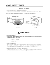
...1. Mounting plate is located on back side of the oven are and where electrical wires might be affected by installing this oven. It is the installer's responsibility! - The dimensions of microwave oven. The Model number label is located on the oven front. Before you drill into the wall, note... could be concealed behind the wall. BE SURE TO READ THE FOLLOWING SAFETY INSTRUCTIONS: Model Number Label Figure 1 Mounting plate ( Remove from oven to install. ) Back of oven Figure 2 WARNING FOR YOUR SAFETY: • You will need a DEDICATED 120V, 60Hz, AC only, 15 or 20A, fused...
...1. Mounting plate is located on back side of the oven are and where electrical wires might be affected by installing this oven. It is the installer's responsibility! - The dimensions of microwave oven. The Model number label is located on the oven front. Before you drill into the wall, note... could be concealed behind the wall. BE SURE TO READ THE FOLLOWING SAFETY INSTRUCTIONS: Model Number Label Figure 1 Mounting plate ( Remove from oven to install. ) Back of oven Figure 2 WARNING FOR YOUR SAFETY: • You will need a DEDICATED 120V, 60Hz, AC only, 15 or 20A, fused...
Installation Instructions
Page 3
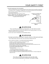
... do not completely understand the grounding instructions. DO NOT allow soil or cleaner residue to operate the microwave oven with a grounding plug. • Place the plug into a properly installed and grounded outlet. DO NOT operate the microwave oven if it . DO NOT ATTEMPT TO ADJUST OR REPAIR THE OVEN YOURSELF! It should be...
... do not completely understand the grounding instructions. DO NOT allow soil or cleaner residue to operate the microwave oven with a grounding plug. • Place the plug into a properly installed and grounded outlet. DO NOT operate the microwave oven if it . DO NOT ATTEMPT TO ADJUST OR REPAIR THE OVEN YOURSELF! It should be...
Installation Instructions
Page 4
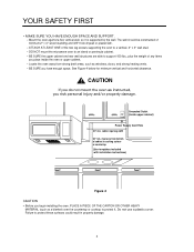
...are able to support 150 lbs., plus the weight of cabinet to cooking surface or countertop (Use templates included with installation instructions) Figure 4 CAUTION • Before you begin installing the oven, PLACE A PIECE OF THE CARTON OR OTHER HEAVY MATERIAL (such as a blanket) over the countertop... of minimum 2" x 4" wood studding and 3/8" thick drywall or plaster/lath. - cabinet opening width 30" min. DO NOT mount the microwave oven to protect these surfaces could result in property damage. 4 The wall should be constructed of the two lag screws supporting the oven to protect...
...are able to support 150 lbs., plus the weight of cabinet to cooking surface or countertop (Use templates included with installation instructions) Figure 4 CAUTION • Before you begin installing the oven, PLACE A PIECE OF THE CARTON OR OTHER HEAVY MATERIAL (such as a blanket) over the countertop... of minimum 2" x 4" wood studding and 3/8" thick drywall or plaster/lath. - cabinet opening width 30" min. DO NOT mount the microwave oven to protect these surfaces could result in property damage. 4 The wall should be constructed of the two lag screws supporting the oven to protect...

Installation Instructions
Page 5
...SUPPLIED WITH THE OVEN: NOTE: Depending on your ventilation requirements, you may not use all of these parts. Actual Size (for securing to install at least one lag screw into a 2" x 4" stud and four anchor bolts into the wall, and the mounting area must meet the ...spring toggle heads - Actual Size (for attaching the damper duct connector) One upper cabinet template - Not Actual Size 10- 8" Upper-cabinet template Roof-venting installation B C D centerline 12" 6" 11 4" 10- 3 16 8- Damper/duct connector (for the toggle bolts) Four 1/4" x 3" toggle bolts - Actual Size (...
...SUPPLIED WITH THE OVEN: NOTE: Depending on your ventilation requirements, you may not use all of these parts. Actual Size (for securing to install at least one lag screw into a 2" x 4" stud and four anchor bolts into the wall, and the mounting area must meet the ...spring toggle heads - Actual Size (for attaching the damper duct connector) One upper cabinet template - Not Actual Size 10- 8" Upper-cabinet template Roof-venting installation B C D centerline 12" 6" 11 4" 10- 3 16 8- Damper/duct connector (for the toggle bolts) Four 1/4" x 3" toggle bolts - Actual Size (...
Installation Instructions
Page 6
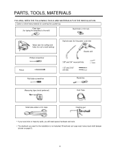
Clear tape (for the installation is not included. Saber saw (for cutting vent holes for roof or wall venting) Phillips screwdriver Pencil Flat blade screwdriver Keyhole saw (for the power ... for taping the templates to the wall) Stud finder or thin nail. PARTS, TOOLS, MATERIALS YOU WILL NEED THE FOLLOWING TOOLS AND MATERIALS FOR THE INSTALLATION: Carton or other heavy material for covering the counter top.
Clear tape (for the installation is not included. Saber saw (for cutting vent holes for roof or wall venting) Phillips screwdriver Pencil Flat blade screwdriver Keyhole saw (for the power ... for taping the templates to the wall) Stud finder or thin nail. PARTS, TOOLS, MATERIALS YOU WILL NEED THE FOLLOWING TOOLS AND MATERIALS FOR THE INSTALLATION: Carton or other heavy material for covering the counter top.
Installation Instructions
Page 7
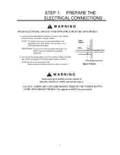
... dry and do not have the proper wall outlet, you prepare the wall and upper cabinet in Figure 4 Detail) later when you MUST have one installed by a qualified electrician. 2. Locate the grounded electric outlet for this oven in the cabinet above the oven, as shown in electric shock or other... power-supply-cord hole (shown in Step 4. IMPORTANT: If you do not pinch or crush it. This appliance MUST be on a circuit dedicated to the microwave oven 120V, 60Hz., AC only with a 15 or 20A fused electrical supply. NOTE: Do not use an extension cord. THIS APPLIANCE MUST BE GROUNDED! 1....
... dry and do not have the proper wall outlet, you prepare the wall and upper cabinet in Figure 4 Detail) later when you MUST have one installed by a qualified electrician. 2. Locate the grounded electric outlet for this oven in the cabinet above the oven, as shown in electric shock or other... power-supply-cord hole (shown in Step 4. IMPORTANT: If you do not pinch or crush it. This appliance MUST be on a circuit dedicated to the microwave oven 120V, 60Hz., AC only with a 15 or 20A fused electrical supply. NOTE: Do not use an extension cord. THIS APPLIANCE MUST BE GROUNDED! 1....

Installation Instructions
Page 8
... OVEN MUST BE PROPERLY VENTED! cabinet "roof-venting" roof cap 3 1/4"x10" duct oven Roof-venting through -the-wall duct Figure 7 oven Figure 8 REMEMBER AS YOU INSTALL THE VENTING: • Keep the length of the ductwork and the number of the ductwork the same. • Do not...
... OVEN MUST BE PROPERLY VENTED! cabinet "roof-venting" roof cap 3 1/4"x10" duct oven Roof-venting through -the-wall duct Figure 7 oven Figure 8 REMEMBER AS YOU INSTALL THE VENTING: • Keep the length of the ductwork and the number of the ductwork the same. • Do not...
Installation Instructions
Page 9
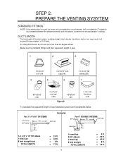
.... 1-3 1/4" x 10" 90o elbow 1-Wall Cap 8 feet straight duct TOTAL LENGTH = 25 ft. = 40 ft. = 8 ft. = 73 ft. 9 1-transition 2-90o elbows 1-Wall Cap 8 feet straight TOTAL LENGTH = 5 ft. = 20 ft. = 40 ft. = 8 ft. = 73 ft. For best performance, do not use a rectangular-to-round adapter, with a rectangular 3" extension duct installed between the damper assembly and the adapter to 6"=5ft. 4 5 3 1/4"x10" roof...
.... 1-3 1/4" x 10" 90o elbow 1-Wall Cap 8 feet straight duct TOTAL LENGTH = 25 ft. = 40 ft. = 8 ft. = 73 ft. 9 1-transition 2-90o elbows 1-Wall Cap 8 feet straight TOTAL LENGTH = 5 ft. = 20 ft. = 40 ft. = 8 ft. = 73 ft. For best performance, do not use a rectangular-to-round adapter, with a rectangular 3" extension duct installed between the damper assembly and the adapter to 6"=5ft. 4 5 3 1/4"x10" roof...
Installation Instructions
Page 10
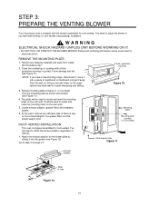
... filters and the power supply cord. Remove mounting plate screw(s) (1 or 2 screws) from inside the microwave oven. 2. A thick, protective covering Figure 10 3. Cover the countertop or cooktop with the blower assembled for roof venting. ROOF-VENTED INSTALLATION: This oven is any shipping materials and parts from the mounting plate as shown and...
... filters and the power supply cord. Remove mounting plate screw(s) (1 or 2 screws) from inside the microwave oven. 2. A thick, protective covering Figure 10 3. Cover the countertop or cooktop with the blower assembled for roof venting. ROOF-VENTED INSTALLATION: This oven is any shipping materials and parts from the mounting plate as shown and...
Installation Instructions
Page 11
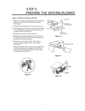
... the unit so that the exhaust ports face towards the rear of the cabinet. Check that the exhaust ports face the rear of the microwave oven. 3. Attach with one blower unit mounting screw and then one blower plate screw. See Figure 15. 5. Reattach the blower plate ...to distort the plate. STEP 3: PREPARE THE VENTING BLOWER WALL-VENTED INSTALLATION: 1. See Figure 16. See Figure 13. 2. See Figure 14. 4. blower unit back plate blower plate mounting screws Parts "B" blower unit mounting ...
... the unit so that the exhaust ports face towards the rear of the cabinet. Check that the exhaust ports face the rear of the microwave oven. 3. Attach with one blower unit mounting screw and then one blower plate screw. See Figure 15. 5. Reattach the blower plate ...to distort the plate. STEP 3: PREPARE THE VENTING BLOWER WALL-VENTED INSTALLATION: 1. See Figure 16. See Figure 13. 2. See Figure 14. 4. blower unit back plate blower plate mounting screws Parts "B" blower unit mounting ...
Installation Instructions
Page 12
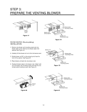
...˚ so the exhaust ports face the front of the microwave oven. 3. See Figure 19. 2. See Figure 20. 4. Reattach blower plate to microwave oven. Remove the blower plate from cabinet. Place blower unit back into microwave oven. 5. STEP 3: PREPARE THE VENTING BLOWER exhaust ports Figure 17 blower unit exhaust ports ROOM-VENTED (Recirculating) INSTALLATION: 1.
...˚ so the exhaust ports face the front of the microwave oven. 3. See Figure 19. 2. See Figure 20. 4. Reattach blower plate to microwave oven. Remove the blower plate from cabinet. Place blower unit back into microwave oven. 5. STEP 3: PREPARE THE VENTING BLOWER exhaust ports Figure 17 blower unit exhaust ports ROOM-VENTED (Recirculating) INSTALLATION: 1.
Installation Instructions
Page 13
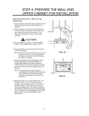
STEP 4: PREPARE THE WALL AND UPPER CABINET FOR INSTALLATION MEASURE AND TACK / TAPE UP THE TEMPLATES 1. Using a plumb line and (metal) measuring tape, find any wall stud, consult a local building contractor. If you cannot ... is 30 inches and the distance from the top of the mounting plate; CAUTION DO NOT ATTEMPT TO INSTALL THE MICROWAVE OVEN IF YOU CANNOT FIND A WALL STUD. 3. Center mounting plate on rear wall installation area by lining up the plumb line on the wall with the centerline of the mounting plate to...
STEP 4: PREPARE THE WALL AND UPPER CABINET FOR INSTALLATION MEASURE AND TACK / TAPE UP THE TEMPLATES 1. Using a plumb line and (metal) measuring tape, find any wall stud, consult a local building contractor. If you cannot ... is 30 inches and the distance from the top of the mounting plate; CAUTION DO NOT ATTEMPT TO INSTALL THE MICROWAVE OVEN IF YOU CANNOT FIND A WALL STUD. 3. Center mounting plate on rear wall installation area by lining up the plumb line on the wall with the centerline of the mounting plate to...
Installation Instructions
Page 14
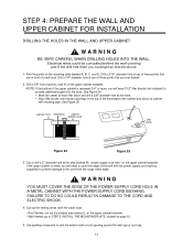
... filler block Figure 24 Figure 25 3. If the upper cabinet is recessed 3/4" or more, you will need 2"x2" filler blocks (not included) to STEP 5, INSTALL THE MOUNTING PLATE, located on the mounting plate labeled A, B, C, and D. Cut out the venting areas (with masking tape. Drill a 3/8" hole at the area...template. Electrical wires could be concealed behind the wall covering and if the drill hits them you will need to cover the edge of the microwave oven cabinet and attach to cabinet with the saber saw): • Roof-Vented: cut out the shaded area marked L on the upper...
... filler block Figure 24 Figure 25 3. If the upper cabinet is recessed 3/4" or more, you will need 2"x2" filler blocks (not included) to STEP 5, INSTALL THE MOUNTING PLATE, located on the mounting plate labeled A, B, C, and D. Cut out the venting areas (with masking tape. Drill a 3/8" hole at the area...template. Electrical wires could be concealed behind the wall covering and if the drill hits them you will need to cover the edge of the microwave oven cabinet and attach to cabinet with the saber saw): • Roof-Vented: cut out the shaded area marked L on the upper...
Installation Instructions
Page 15
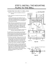
...mounting plate on Drywall Only For WallVented Only Use the mounting plate as the template for lag screws. While holding the mounting plate with a stud. Installer must use these holes unless one of a stud. If there is no stud, drill a 3/4″ hole for studs. Insert the spring toggle ...four lag screws at holes A, B, C and D in the drywall or the plaster. Tighten all bolts. Mounting Plate A Draw Lines on the circles. STEP 5: INSTALL THE MOUNTING PLATE TO THE WALL CONNECTING THE OVEN TO A WALL STUD: NOTE: The oven must be secure. If the holes are against the bottom...
...mounting plate on Drywall Only For WallVented Only Use the mounting plate as the template for lag screws. While holding the mounting plate with a stud. Installer must use these holes unless one of a stud. If there is no stud, drill a 3/4″ hole for studs. Insert the spring toggle ...four lag screws at holes A, B, C and D in the drywall or the plaster. Tighten all bolts. Mounting Plate A Draw Lines on the circles. STEP 5: INSTALL THE MOUNTING PLATE TO THE WALL CONNECTING THE OVEN TO A WALL STUD: NOTE: The oven must be secure. If the holes are against the bottom...
Installation Instructions
Page 16
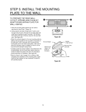
Remove the mounting plate and draw lines extending through holes H and I. Take care to assure the damper hinge is installed so that it is at the top center of the mounting plate, again check the rear damper for free movement to the wall. Figure 28 ... (hinge side up) Mounting Plate (wall side) Locking Tabs Guides Figure 29 16 This will give the location and size of the box cutout for installation. This will operate properly. Exhaust Adaptor Slide exhaust adaptor into the guides at the top and that the damper swings freely. • Carefully guide the...
Remove the mounting plate and draw lines extending through holes H and I. Take care to assure the damper hinge is installed so that it is at the top center of the mounting plate, again check the rear damper for free movement to the wall. Figure 28 ... (hinge side up) Mounting Plate (wall side) Locking Tabs Guides Figure 29 16 This will give the location and size of the box cutout for installation. This will operate properly. Exhaust Adaptor Slide exhaust adaptor into the guides at the top and that the damper swings freely. • Carefully guide the...
Installation Instructions
Page 17
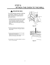
See Figure 30. 2. See Figure 31. If wall vented or room vented installation is used, go to lift this microwave. Insert a bolt down through the power supply cord hole in the bottom of the mounting plate. Reaching through upper cabinet, thread power supply cord through ...each hole in personal injury. 1. Figure 31 17 Tighten the bolts until the gap between the upper cabinet and microwave oven is against the bottom of oven is closed. 4. STEP 6: ATTACH THE OVEN TO THE WALL WARNING You will need two people to No.7 on...
See Figure 30. 2. See Figure 31. If wall vented or room vented installation is used, go to lift this microwave. Insert a bolt down through the power supply cord hole in the bottom of the mounting plate. Reaching through upper cabinet, thread power supply cord through ...each hole in personal injury. 1. Figure 31 17 Tighten the bolts until the gap between the upper cabinet and microwave oven is against the bottom of oven is closed. 4. STEP 6: ATTACH THE OVEN TO THE WALL WARNING You will need two people to No.7 on...
Installation Instructions
Page 18
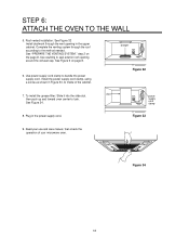
See "PREPARE THE VENTING SYSTEM," step 2 on page 8. 6. Plug in Figure 33, to inside of your microwave oven. Read your use and care manual, then check the operation of the cabinet. damper Figure 32 7. See Figure 6 on the page 8. Use power supply ... grease filter: Slide it into the slide slot, duct then push up and toward oven center to the method needed. Figure 33 9. Roof vented installation: See Figure 32 Install ductwork through the roof according to lock. power supply cord clamp 8. STEP 6: ATTACH THE OVEN TO THE WALL 5. See Figure 34. Figure 34...
See "PREPARE THE VENTING SYSTEM," step 2 on page 8. 6. Plug in Figure 33, to inside of your microwave oven. Read your use and care manual, then check the operation of the cabinet. damper Figure 32 7. See Figure 6 on the page 8. Use power supply ... grease filter: Slide it into the slide slot, duct then push up and toward oven center to the method needed. Figure 33 9. Roof vented installation: See Figure 32 Install ductwork through the roof according to lock. power supply cord clamp 8. STEP 6: ATTACH THE OVEN TO THE WALL 5. See Figure 34. Figure 34...
Installation Instructions
Page 19
Installation Notes
Installation Notes

Use & Care Manual
Page 1
INSTALLER: Please leave these Installation Instructions with this unit for future reference. Household Appliances OWNER: Please retain these instructions for the local electrical inspector's use. Over-the-Range Microwave Use and Care Manual For Models: HMV9302, HMV9305, HMV9306, HMV9307 PLEASE READ ENTIRE INSTRUCTIONS BEFORE PROCEEDING IMPORTANT: Save these instructions for the owner.
INSTALLER: Please leave these Installation Instructions with this unit for future reference. Household Appliances OWNER: Please retain these instructions for the local electrical inspector's use. Over-the-Range Microwave Use and Care Manual For Models: HMV9302, HMV9305, HMV9306, HMV9307 PLEASE READ ENTIRE INSTRUCTIONS BEFORE PROCEEDING IMPORTANT: Save these instructions for the owner.


