Installation Instructions
Page 3
Attaching stainless steel front panel to connect the water ...15 8. Adjusting the door opening angle (refrigerator compartment door 21 19. Attaching an alternative anti-tip device 14 7. Preparing to the freezer compartment drawer 20 16. Pushing the appliance into the installation cavity 16 10. Changing the door spring ...22 3 Removing the packaging ...12 4. Attaching...
Attaching stainless steel front panel to connect the water ...15 8. Adjusting the door opening angle (refrigerator compartment door 21 19. Attaching an alternative anti-tip device 14 7. Preparing to the freezer compartment drawer 20 16. Pushing the appliance into the installation cavity 16 10. Changing the door spring ...22 3 Removing the packaging ...12 4. Attaching...

Installation Instructions
Page 4
... and be secured to improper installation is the responsibility of tipping forward. m CAUTION Skill - Installation of not observing this appliance requires basic mechanical, carpentry and plumbing skills. See the Owner's Manual for local inspector's use by a qualified fitter. ...m CAUTION m CAUTION - Anti-tip protection is completely installed and secured per installation instructions. Keep doors closed until the appliance is required. TWO PEOPLE ARE REQUIRED FOR PROPER INSTALLATION. Level - Keep these instructions for warranty information. latest edition/Provincial...
... and be secured to improper installation is the responsibility of tipping forward. m CAUTION Skill - Installation of not observing this appliance requires basic mechanical, carpentry and plumbing skills. See the Owner's Manual for local inspector's use by a qualified fitter. ...m CAUTION m CAUTION - Anti-tip protection is completely installed and secured per installation instructions. Keep doors closed until the appliance is required. TWO PEOPLE ARE REQUIRED FOR PROPER INSTALLATION. Level - Keep these instructions for warranty information. latest edition/Provincial...

Installation Instructions
Page 5
... less than 6" (160 mm). Use the Extreme Combination Side-by the design of the kitchen and the function of the appliance is visible, a side panel must be used. See the section on "Optional accessories". - Individual unit At the end of the kitchen units If ...placed in the cavity. Minimum thickness of the side panel are opened at the same time. - The dimensions of the partition 5/8" (16 mm). 5 Individual appliances with partition 1. 2. - The side panel must be connected firmly to prevent damage if the doors are taken from the opposite cavity wall. When dimensioning the...
... less than 6" (160 mm). Use the Extreme Combination Side-by the design of the kitchen and the function of the appliance is visible, a side panel must be used. See the section on "Optional accessories". - Individual unit At the end of the kitchen units If ...placed in the cavity. Minimum thickness of the side panel are opened at the same time. - The dimensions of the partition 5/8" (16 mm). 5 Individual appliances with partition 1. 2. - The side panel must be connected firmly to prevent damage if the doors are taken from the opposite cavity wall. When dimensioning the...
Installation Instructions
Page 6
If installation next to adjacent and overhead furniture/fixtures. In particular ensure that the cavity is very heavy - Furniture/fixtures The new appliance is screwed securely to a heat source is unavoidable, use a suitable insulating plate or observe the following minimum distances from the heat ...by suitable means, e.g. for empty weight see the following table: BM (Bottom Mount) 36" approx. 430 Ibs / 195 kg Installation room The appliance should not drop below 55 °F (13 °C) or rise above 110 °F (43 °C), otherwise malfunctions may occur. The base must...
If installation next to adjacent and overhead furniture/fixtures. In particular ensure that the cavity is very heavy - Furniture/fixtures The new appliance is screwed securely to a heat source is unavoidable, use a suitable insulating plate or observe the following minimum distances from the heat ...by suitable means, e.g. for empty weight see the following table: BM (Bottom Mount) 36" approx. 430 Ibs / 195 kg Installation room The appliance should not drop below 55 °F (13 °C) or rise above 110 °F (43 °C), otherwise malfunctions may occur. The base must...
Installation Instructions
Page 7
...a malfunction or breakdown, grounding will reduce the risk of the automatic ice maker. Connecting the water m CAUTION m Only connect the appliance to plastic plumbing lines, gas lines or water pipes. The installation must be purchased separately. For the permitted installation areas and dimensions see... electric shock by a licensed electrician only. The water pressure must not be grounded. Please observe in this coherence the following table: Appliance Bottom Freezer 36" Maximum load at the side on the left (b) or underneath (c). Attach a separate shut-off valve for the ...
...a malfunction or breakdown, grounding will reduce the risk of the automatic ice maker. Connecting the water m CAUTION m Only connect the appliance to plastic plumbing lines, gas lines or water pipes. The installation must be purchased separately. For the permitted installation areas and dimensions see... electric shock by a licensed electrician only. The water pressure must not be grounded. Please observe in this coherence the following table: Appliance Bottom Freezer 36" Maximum load at the side on the left (b) or underneath (c). Attach a separate shut-off valve for the ...

Installation Instructions
Page 9
e) Unit dimensions f) Wooden door panel dimensions 9 b) Dimensions may vary depending on installation, panel thickness and kitchen hardware. Appliance dimensions Legend: a) Adjustment in levelling legs +13/8" (35 mm) / -1/2" (13 mm). d) This dimension may vary.
e) Unit dimensions f) Wooden door panel dimensions 9 b) Dimensions may vary depending on installation, panel thickness and kitchen hardware. Appliance dimensions Legend: a) Adjustment in levelling legs +13/8" (35 mm) / -1/2" (13 mm). d) This dimension may vary.

Installation Instructions
Page 10
...tilt protection, length according to protect the floor from specialist outlets Ice maker installation kit 1/4" OD copper line For connecting appliances which require water, e.g. Required accessories and tools Supplied accessories - Installation kit Optional accessories Extreme Combination Side-by -Side ...16" (8 mm) hex nut driver - Marking-out level, length at least 4' (1.2 m) for individual appliances or 7' (2.0 m) for Side-by -Side Heating kit If the gap between the appliances is less than 6" (160 mm). Torx screwdriver T20 - Operating instructions - Tools - Other required accessories ...
...tilt protection, length according to protect the floor from specialist outlets Ice maker installation kit 1/4" OD copper line For connecting appliances which require water, e.g. Required accessories and tools Supplied accessories - Installation kit Optional accessories Extreme Combination Side-by -Side ...16" (8 mm) hex nut driver - Marking-out level, length at least 4' (1.2 m) for individual appliances or 7' (2.0 m) for Side-by -Side Heating kit If the gap between the appliances is less than 6" (160 mm). Torx screwdriver T20 - Operating instructions - Tools - Other required accessories ...

Installation Instructions
Page 11
...cavity complies with suitable means of the subsequent furniture front, thoroughly check that the installation cavity complies with all requirements for appliances with ice maker). All furniture parts in the vicinity of the cavity. „ Check that adjacent furniture/fixtures do ... it from overturning. Also follow the instructions in the section on "Connecting the water". „ Check attachment of the appliance m CAUTION m The appliance is 84" (2134 mm) tall. Transport of the adjacent furniture/fixtures. Installation instructions 1. Follow the instructions in the ...
...cavity complies with suitable means of the subsequent furniture front, thoroughly check that the installation cavity complies with all requirements for appliances with ice maker). All furniture parts in the vicinity of the cavity. „ Check that adjacent furniture/fixtures do ... it from overturning. Also follow the instructions in the section on "Connecting the water". „ Check attachment of the appliance m CAUTION m The appliance is 84" (2134 mm) tall. Transport of the adjacent furniture/fixtures. Installation instructions 1. Follow the instructions in the ...

Installation Instructions
Page 12
... tape which protect the shelves and storage compartments inside the appliance. The appliance is being unpacked. - B B A „ Check appliance for attaching the edge protection to the appliance. Risk of the appliance. - The appliance may be damaged. Be careful, otherwise people who are closed... packaging: - Remove accessories from damage during installation: „ Attach a residual piece of the appliance. - Carefully open the appliance - risk of the refrigerator compartment has to the door of tipping over while it is visibly damaged. The folding rail attached...
... tape which protect the shelves and storage compartments inside the appliance. The appliance is being unpacked. - B B A „ Check appliance for attaching the edge protection to the appliance. Risk of the appliance. - The appliance may be damaged. Be careful, otherwise people who are closed... packaging: - Remove accessories from damage during installation: „ Attach a residual piece of the appliance. - Carefully open the appliance - risk of the refrigerator compartment has to the door of tipping over while it is visibly damaged. The folding rail attached...

Installation Instructions
Page 13
...m Assure that there are identified differently. The supplied set contains fastening screws for each appliance. - The anti-tip-angles must have a minimum length of 41/8" (105 mm) over the appliance to the local conditions. Select the fastening screws according to ensure a secure stand of..."Installation dimensions". „ Attach the anti-tip-angles completely. The length of the appliance. If this minimum length cannot be observed for structural conditions it is possible to the appliance! To do this , comply with wood screws 5. Specify the detailed dimensions according to...
...m Assure that there are identified differently. The supplied set contains fastening screws for each appliance. - The anti-tip-angles must have a minimum length of 41/8" (105 mm) over the appliance to the local conditions. Select the fastening screws according to ensure a secure stand of..."Installation dimensions". „ Attach the anti-tip-angles completely. The length of the appliance. If this minimum length cannot be observed for structural conditions it is possible to the appliance! To do this , comply with wood screws 5. Specify the detailed dimensions according to...

Installation Instructions
Page 14
... and screws m CAUTION m Always wear safety glasses and other necessary protective devices or apparel when installing or working with anchors. The beam must cover the appliance by at least 2" (50.8 mm). 6. Not recommended for this anchor. „ Saw the wooden beam (cross section min. 3" x 4") to cure. Length ...„ Predrill the wooden beam. „ Attach the wooden beam to the cavity width, thereby ensuring that there is no play between the appliance and the anti-tip device. Risk of the cavity. 14 If possible, always screw the wooden beam to existing studs on the rear panel ...
... and screws m CAUTION m Always wear safety glasses and other necessary protective devices or apparel when installing or working with anchors. The beam must cover the appliance by at least 2" (50.8 mm). 6. Not recommended for this anchor. „ Saw the wooden beam (cross section min. 3" x 4") to cure. Length ...„ Predrill the wooden beam. „ Attach the wooden beam to the cavity width, thereby ensuring that there is no play between the appliance and the anti-tip device. Risk of the cavity. 14 If possible, always screw the wooden beam to existing studs on the rear panel ...
Installation Instructions
Page 15
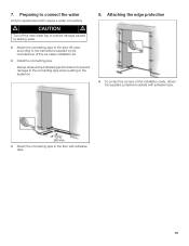
... to prevent damage to the floor with adhesive tape. „ Attach the connecting pipe to the connecting pipe when pushing in the appliance. 8. Preparing to connect the water (only for appliances which require a water connection) m CAUTION m Turn off the main water tap to prevent damage caused by leaking water. „ Attach the...
... to prevent damage to the floor with adhesive tape. „ Attach the connecting pipe to the connecting pipe when pushing in the appliance. 8. Preparing to connect the water (only for appliances which require a water connection) m CAUTION m Turn off the main water tap to prevent damage caused by leaking water. „ Attach the...
Installation Instructions
Page 16
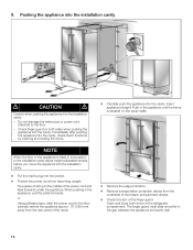
...pushing in the gap between the appliance and cavity wall. 16 9. Do not damage the water pipe or power cord attached to the middle of the refrigerator compartment. Pushing the appliance into the installation cavity m CAUTION m Caution when pushing the appliance into the cavity. NOTE When ...the floor or the appliance is situated on both doors of the power cord and feed...
...pushing in the gap between the appliance and cavity wall. 16 9. Do not damage the water pipe or power cord attached to the middle of the refrigerator compartment. Pushing the appliance into the installation cavity m CAUTION m Caution when pushing the appliance into the cavity. NOTE When ...the floor or the appliance is situated on both doors of the power cord and feed...

Installation Instructions
Page 17
... compartment drawer „ Loosen and unscrew nuts on the left and right, etc.. - When adjusting the height, align this installation manual, rotate the appliance all be aligned. „ Do not loosen the screws on the top of this mark at the rear. - Removing stainless steel front panel from ... brackets. Front: Rear: with open-ended wrench 1/2" (SW13) with the furniture fronts. The adjustment of the rear feet is facilitated if the appliance is used as an alternative anti-tip device according to point 6 of the door. The height-adjustable feet at the front and rear can all...
... compartment drawer „ Loosen and unscrew nuts on the left and right, etc.. - When adjusting the height, align this installation manual, rotate the appliance all be aligned. „ Do not loosen the screws on the top of this mark at the rear. - Removing stainless steel front panel from ... brackets. Front: Rear: with open-ended wrench 1/2" (SW13) with the furniture fronts. The adjustment of the rear feet is facilitated if the appliance is used as an alternative anti-tip device according to point 6 of the door. The height-adjustable feet at the front and rear can all...

Installation Instructions
Page 18
.... that the finger guard functions by opening and closing the two refrigerator compartment doors several times. „ Open one door of the refrigerator compartment. „ Pull finger guard all the way out of the gap between the appliance and cavity wall. „ Screw the frame to the cavity... It is very important to the cavity wall (4 screws). „ Push the finger guard through the gap between the appliance and cavity wall 18 12. Attaching the appliance in the cavity, check - Screw frame to comply with this dimension for the subsequent alignment of the furniture fronts. &#...
.... that the finger guard functions by opening and closing the two refrigerator compartment doors several times. „ Open one door of the refrigerator compartment. „ Pull finger guard all the way out of the gap between the appliance and cavity wall. „ Screw the frame to the cavity... It is very important to the cavity wall (4 screws). „ Push the finger guard through the gap between the appliance and cavity wall 18 12. Attaching the appliance in the cavity, check - Screw frame to comply with this dimension for the subsequent alignment of the furniture fronts. &#...

Installation Instructions
Page 19
.... 13. Tighten hand-tight. „ Using the open-ended wrench, tighten the union nut. Connecting the water to the location of the connection on the appliance (2.). „ Push the union nut and seal onto the water pipe. „ Push the end of the water pipe into place. „ Remove base panel... the base panel. Check the connection on the union nut (3.). NOTE When connecting the water pipe to the base panel and press firmly into the appliance connection and screw on the shut-off valve and main water tap. Do not cover ventilation slots in all the way. 19 Risk of the...
.... 13. Tighten hand-tight. „ Using the open-ended wrench, tighten the union nut. Connecting the water to the location of the connection on the appliance (2.). „ Push the union nut and seal onto the water pipe. „ Push the end of the water pipe into place. „ Remove base panel... the base panel. Check the connection on the union nut (3.). NOTE When connecting the water pipe to the base panel and press firmly into the appliance connection and screw on the shut-off valve and main water tap. Do not cover ventilation slots in all the way. 19 Risk of the...

Installation Instructions
Page 21
... the finger guard is correctly attached to adjust the door opening angle. Commissioning the appliance m CAUTION m Check that the finger guard slides smoothly forwards and backwards when the refrigerator compartment doors open and close. Adjusting the door opening angle (refrigerator compartment door) Depending on the freezer compartment drawer into the gap between stainless...
... the finger guard is correctly attached to adjust the door opening angle. Commissioning the appliance m CAUTION m Check that the finger guard slides smoothly forwards and backwards when the refrigerator compartment doors open and close. Adjusting the door opening angle (refrigerator compartment door) Depending on the freezer compartment drawer into the gap between stainless...

Instructions for Use
Page 3
... in setup mode 15 Vacation Mode 16 Sabbath Mode 16 Refrigerating 16 Freezing and storing 17 IceMaker 18 Operating noises 18 How to save energy 19 Defrosting 19 Cleaning the appliance 19 Odors 19 Warning messages via the display 20 Appliance selfĆtest 20 Resetting factory settings 21 Water filter 21 Troubleshooting 24 Changing...
... in setup mode 15 Vacation Mode 16 Sabbath Mode 16 Refrigerating 16 Freezing and storing 17 IceMaker 18 Operating noises 18 How to save energy 19 Defrosting 19 Cleaning the appliance 19 Odors 19 Warning messages via the display 20 Appliance selfĆtest 20 Resetting factory settings 21 Water filter 21 Troubleshooting 24 Changing...

Instructions for Use
Page 4
.... Some local regulations may adhere to these instructions to whether the appliance has been properly grounded. Use this appliance only for the electric current. After your refrigerator before it is plugged in electric shock. In refrigerators with an automatic icemaker, avoid contact with the moving parts of ... be grounded. A burnedĆout light bulb may result in . 7. Before You Throw Away Your Old Refrigeration Product: - Never ground the appliance to the light circuit. NOTE: We strongly recommend that children may not easily climb inside. e WARNING RISK OF CHILD...
.... Some local regulations may adhere to these instructions to whether the appliance has been properly grounded. Use this appliance only for the electric current. After your refrigerator before it is plugged in electric shock. In refrigerators with an automatic icemaker, avoid contact with the moving parts of ... be grounded. A burnedĆout light bulb may result in . 7. Before You Throw Away Your Old Refrigeration Product: - Never ground the appliance to the light circuit. NOTE: We strongly recommend that children may not easily climb inside. e WARNING RISK OF CHILD...

Instructions for Use
Page 5
... believed to ensure that used to draw the user's attention to something in perfect condition. This appliance is removed for local inspector's use only. 5 CFC's are throwing away an old refrigeration product, make sure the CFC refrigerant is designed for the next owner. If you intentionally release this warning. i This symbol is in...
... believed to ensure that used to draw the user's attention to something in perfect condition. This appliance is removed for local inspector's use only. 5 CFC's are throwing away an old refrigeration product, make sure the CFC refrigerant is designed for the next owner. If you intentionally release this warning. i This symbol is in...