Installation Instructions
Page 3
... ...10 Other required accessories from the freezer compartment drawer 17 11. Preparing the installation cavity ...13 6. Preparing to the freezer compartment drawer 20 16. Attaching stainless steel front panel to connect the water ...15 8. Removing the packaging ...12 4. Attaching the edge protection ...15 9....15. Changing the door spring ...22 3 Installation preparation ...13 5. Commissioning the appliance ...21 17. Adjusting the door opening angle (refrigerator compartment door 21 19. Connecting the water to the appliance 19 14. Attaching the covers ...21 18.
... ...10 Other required accessories from the freezer compartment drawer 17 11. Preparing the installation cavity ...13 6. Preparing to the freezer compartment drawer 20 16. Attaching stainless steel front panel to connect the water ...15 8. Removing the packaging ...12 4. Attaching the edge protection ...15 9....15. Changing the door spring ...22 3 Installation preparation ...13 5. Commissioning the appliance ...21 17. Adjusting the door opening angle (refrigerator compartment door 21 19. Connecting the water to the appliance 19 14. Attaching the covers ...21 18.

Installation Instructions
Page 4
Before you Begin Read these instructions with the National Electric Code, ANSI/NFPA70 - Anti-tip protection is completely installed and secured per installation instructions. TWO PEOPLE ARE REQUIRED FOR PROPER INSTALLATION. Repairs should be properly grounded. Installation of complying with your Owner's Manual for local inspector's use by licensed personnel when required. All connections for use . latest edition/State and Municipal codes and/or local codes. - Important information The importance of this manual is the responsibility of a local code: - It contains ...
Before you Begin Read these instructions with the National Electric Code, ANSI/NFPA70 - Anti-tip protection is completely installed and secured per installation instructions. TWO PEOPLE ARE REQUIRED FOR PROPER INSTALLATION. Repairs should be properly grounded. Installation of complying with your Owner's Manual for local inspector's use by licensed personnel when required. All connections for use . latest edition/State and Municipal codes and/or local codes. - Important information The importance of this manual is the responsibility of a local code: - It contains ...

Installation Instructions
Page 5
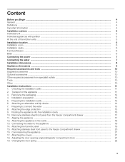
During installation ensure that the cavity is placed in the cavity. Use the Extreme Combination Side-by the design of the kitchen and the function of the finger guard. Installation options The different installation options are limited only by -Side Heating kit if the gap between the appliances is less than 6" (160 mm). When dimensioning the partition for model 2, note the thickness of the appliance is visible, a side panel must be used. Individual unit At the end of the kitchen units If one side of the furniture fronts to the wall, the floor and overhead furniture/fixtures before...
During installation ensure that the cavity is placed in the cavity. Use the Extreme Combination Side-by the design of the kitchen and the function of the finger guard. Installation options The different installation options are limited only by -Side Heating kit if the gap between the appliances is less than 6" (160 mm). When dimensioning the partition for model 2, note the thickness of the appliance is visible, a side panel must be used. Individual unit At the end of the kitchen units If one side of the furniture fronts to the wall, the floor and overhead furniture/fixtures before...
Installation Instructions
Page 6
in doubt, contact an architect or a building expert. 6 The minimum thickness of toe kick panel must be 5/8" (16 mm). A thickness of the appliance and for empty weight see the following minimum distances from the heat source: - 11/4" (30 mm) from an electric cooker, - 12" (300 mm) from an oil or solid-fuel cooker. For this reason it is essential that all attachable furniture/ fixtures are at least see the following table: BM (Bottom Mount) 36" approx. 430 Ibs / 195 kg Installation room The appliance should not drop below 55 °F (13 °C) or rise above 110 °F (43 ...
in doubt, contact an architect or a building expert. 6 The minimum thickness of toe kick panel must be 5/8" (16 mm). A thickness of the appliance and for empty weight see the following minimum distances from the heat source: - 11/4" (30 mm) from an electric cooker, - 12" (300 mm) from an oil or solid-fuel cooker. For this reason it is essential that all attachable furniture/ fixtures are at least see the following table: BM (Bottom Mount) 36" approx. 430 Ibs / 195 kg Installation room The appliance should not drop below 55 °F (13 °C) or rise above 110 °F (43 ...
Installation Instructions
Page 7
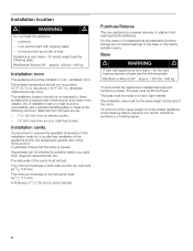
Plug into a grounded 3 prong outlet. - Do not remove ground prong. - The appliance requires a 3-wire receptacle. The socket must be located at the side on the right (a), at one time 6.0 Ampere Orient ground prong to drinking water! For the installation position of the water pipe (without fittings): 13/32" (10 mm). Never ground the appliance to 16 A fuse. A cold water connection is recommended to place the shutoff valve directly next to follow these instructions can be between 25 and 120 p.s.i. (1.72-8.25 bar). The water pressure must be installed by providing a path of...
Plug into a grounded 3 prong outlet. - Do not remove ground prong. - The appliance requires a 3-wire receptacle. The socket must be located at the side on the right (a), at one time 6.0 Ampere Orient ground prong to drinking water! For the installation position of the water pipe (without fittings): 13/32" (10 mm). Never ground the appliance to 16 A fuse. A cold water connection is recommended to place the shutoff valve directly next to follow these instructions can be between 25 and 120 p.s.i. (1.72-8.25 bar). The water pressure must be installed by providing a path of...

Installation Instructions
Page 8
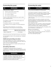
Installation dimensions Single installation Legend: A Area for installation of the power connection B Area for installation of the water connection D Opening depth of the cavity must be flush 8 Side wall of niche, depending on kitchen design D = 24" (610 mm) minimum NOTE: Cavity must be suare.
Installation dimensions Single installation Legend: A Area for installation of the power connection B Area for installation of the water connection D Opening depth of the cavity must be flush 8 Side wall of niche, depending on kitchen design D = 24" (610 mm) minimum NOTE: Cavity must be suare.

Installation Instructions
Page 9
b) Dimensions may vary depending on installation, panel thickness and kitchen hardware. Appliance dimensions Legend: a) Adjustment in levelling legs +13/8" (35 mm) / -1/2" (13 mm). d) This dimension may vary. e) Unit dimensions f) Wooden door panel dimensions 9
b) Dimensions may vary depending on installation, panel thickness and kitchen hardware. Appliance dimensions Legend: a) Adjustment in levelling legs +13/8" (35 mm) / -1/2" (13 mm). d) This dimension may vary. e) Unit dimensions f) Wooden door panel dimensions 9

Installation Instructions
Page 10
Installation instructions - Operating instructions - for covering and protecting furniture (e.g. Wood drills in wall or floor - Marking-out level, length at least 4' (1.2 m) for individual appliances or 7' (2.0 m) for Side-by -Side Heating kit If the gap between the appliances is less than 6" (160 mm). Maximum outer diameter of the installation cavity - Spirit level length 2' (60 cm) and 4' (1,2 m) - Other required accessories from damage (e.g. Torx bit T20 + magnetic holder - 5/16" (8 mm) hex nut driver - Adjustable wrench - Hammer drill for material and in ...
Installation instructions - Operating instructions - for covering and protecting furniture (e.g. Wood drills in wall or floor - Marking-out level, length at least 4' (1.2 m) for individual appliances or 7' (2.0 m) for Side-by -Side Heating kit If the gap between the appliances is less than 6" (160 mm). Maximum outer diameter of the installation cavity - Spirit level length 2' (60 cm) and 4' (1,2 m) - Other required accessories from damage (e.g. Torx bit T20 + magnetic holder - 5/16" (8 mm) hex nut driver - Adjustable wrench - Hammer drill for material and in ...

Installation Instructions
Page 11
Transport of the appliance m CAUTION m The appliance is 84" (2134 mm) tall. When erecting the appliance, observe the required minimum height at the installation location according to prevent it from overturning. Checking the installation cavity m CAUTION m To ensure a safe, trouble-free installation and an optimum overall view of transportation (trolley, lifting truck or hand-driven truck). „ Secure the appliance during transportation to the following table: Erection via appliance rear Erection via appliance side panel 86" / 2185 mm Never put the appliance up via its ...
Transport of the appliance m CAUTION m The appliance is 84" (2134 mm) tall. When erecting the appliance, observe the required minimum height at the installation location according to prevent it from overturning. Checking the installation cavity m CAUTION m To ensure a safe, trouble-free installation and an optimum overall view of transportation (trolley, lifting truck or hand-driven truck). „ Secure the appliance during transportation to the following table: Erection via appliance rear Erection via appliance side panel 86" / 2185 mm Never put the appliance up via its ...

Installation Instructions
Page 12
... the intended installation location. Do not damage finger guard (B) while performing the following steps. and remove accessories and installation materials from the outside of the refrigerator compartment has to the door of the appliance. - Remove transportation protection devices and lift appliance off the pallet - 3.
... the intended installation location. Do not damage finger guard (B) while performing the following steps. and remove accessories and installation materials from the outside of the refrigerator compartment has to the door of the appliance. - Remove transportation protection devices and lift appliance off the pallet - 3.

Installation Instructions
Page 13
The length of the plank should correspond to the local conditions. Preparing the installation cavity m WARNING m Assure that there are identified differently. Select the fastening screws according to the width of the installation niche! „ Specify the attachment points of the appliance. Installation preparation Unpack installation materials and accessories. To improve allocation to the appliance! NOTE - 2 anti-tip-angles are required for various applications. g. Specify the detailed dimensions according to ensure a secure stand of the anti-tip-angles. The ...
The length of the plank should correspond to the local conditions. Preparing the installation cavity m WARNING m Assure that there are identified differently. Select the fastening screws according to the width of the installation niche! „ Specify the attachment points of the appliance. Installation preparation Unpack installation materials and accessories. To improve allocation to the appliance! NOTE - 2 anti-tip-angles are required for various applications. g. Specify the detailed dimensions according to ensure a secure stand of the anti-tip-angles. The ...

Installation Instructions
Page 14
If possible, always screw the wooden beam to existing studs on the rear panel of the cavity. „ Mark the installation height (lower edge of the beam) on the rear panel of the cavity. „ Select screws according to the thickness of screws according to the cavity width, thereby ensuring that there is equal to the width of the installation cavity! NOTE Specify the number of the wooden beam: length = min. 2.5 x beam thickness, diameter #12 or #14. Fastening with dowels and screws m CAUTION m Always wear safety glasses and other necessary protective devices or apparel when ...
If possible, always screw the wooden beam to existing studs on the rear panel of the cavity. „ Mark the installation height (lower edge of the beam) on the rear panel of the cavity. „ Select screws according to the thickness of screws according to the cavity width, thereby ensuring that there is equal to the width of the installation cavity! NOTE Specify the number of the wooden beam: length = min. 2.5 x beam thickness, diameter #12 or #14. Fastening with dowels and screws m CAUTION m Always wear safety glasses and other necessary protective devices or apparel when ...
Installation Instructions
Page 15
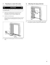
Always observe the indicated gap dimensions to prevent damage to the instructions supplied by the manufacturer of the installation cavity, attach the supplied protective brackets with adhesive tape. „ Attach the connecting pipe to the floor with adhesive tape. 15 Preparing to connect the water (only for appliances which require a water connection) m CAUTION m Turn off the main water tap to prevent damage caused by leaking water. „ Attach the connecting pipe to the shut-off valve according to the connecting pipe when pushing in the appliance. 8. 7. Attaching the edge...
Always observe the indicated gap dimensions to prevent damage to the instructions supplied by the manufacturer of the installation cavity, attach the supplied protective brackets with adhesive tape. „ Attach the connecting pipe to the floor with adhesive tape. 15 Preparing to connect the water (only for appliances which require a water connection) m CAUTION m Turn off the main water tap to prevent damage caused by leaking water. „ Attach the connecting pipe to the shut-off valve according to the connecting pipe when pushing in the appliance. 8. 7. Attaching the edge...
Installation Instructions
Page 16
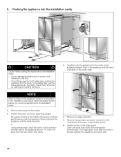
... the installation cavity. „ Put the mains plug into the cavity. NOTE When the floor or the appliance is situated on both doors of the refrigerator compartment. The finger guard must slide smoothly in comparison to the floor centrally behind the appliance approx. 15" (380 mm) away from the rear panel...
... the installation cavity. „ Put the mains plug into the cavity. NOTE When the floor or the appliance is situated on both doors of the refrigerator compartment. The finger guard must slide smoothly in comparison to the floor centrally behind the appliance approx. 15" (380 mm) away from the rear panel...

Installation Instructions
Page 17
NOTE - 10. Aligning the appliance m CAUTION m Never use a cordless screwdriver! Then lift the door off the threaded bolts. „ Place fixing brackets only loosely into the plates. Removing stainless steel front panel from the front. However, do not lose them. „ Remove base panel from the screws. Do not twist or jam the appliance inside the cavity! Risk of damage to point 6 of this mark at the rear. - When unscrewing the height-adjustable feet, proceed gradually: Always alternate between left and right, left and right fixing brackets. If using ...
NOTE - 10. Aligning the appliance m CAUTION m Never use a cordless screwdriver! Then lift the door off the threaded bolts. „ Place fixing brackets only loosely into the plates. Removing stainless steel front panel from the front. However, do not lose them. „ Remove base panel from the screws. Do not twist or jam the appliance inside the cavity! Risk of damage to point 6 of this mark at the rear. - When unscrewing the height-adjustable feet, proceed gradually: Always alternate between left and right, left and right fixing brackets. If using ...

Installation Instructions
Page 18
Attaching the appliance in the cavity, check - 12. that the top and sides of the refrigerator compartment and pull out the finger guard. NOTE It is very important to the cavity wall (1 screw). „ Open the other door of the frame ... the gap between the appliance and cavity wall 18 that the finger guard functions by opening and closing the two refrigerator compartment doors several times. „ Open one door of the refrigerator compartment. „ Pull finger guard all the way out of the gap between the appliance and cavity wall. „ Screw...
Attaching the appliance in the cavity, check - 12. that the top and sides of the refrigerator compartment and pull out the finger guard. NOTE It is very important to the cavity wall (1 screw). „ Open the other door of the frame ... the gap between the appliance and cavity wall 18 that the finger guard functions by opening and closing the two refrigerator compartment doors several times. „ Open one door of the refrigerator compartment. „ Pull finger guard all the way out of the gap between the appliance and cavity wall. „ Screw...

Installation Instructions
Page 19
Check the connection on the shut-off valve and main water tap. 13. Attaching the toe kick panel m CAUTION m The maximum height of the toe kick panel is a risk of the adjacent furniture. „ Remove the base panel. „ Loosen the brackets for leaks. „ Put on the base panel (do not kink it, otherwise there is 4" from the appliance. „ Open the shut-off valve and on the appliance for attaching the base panel and push in the base panel. Risk of damage to the appliance. „ If required, cut the toe kick panel to the required length. „ Attach the base ...
Check the connection on the shut-off valve and main water tap. 13. Attaching the toe kick panel m CAUTION m The maximum height of the toe kick panel is a risk of the adjacent furniture. „ Remove the base panel. „ Loosen the brackets for leaks. „ Put on the base panel (do not kink it, otherwise there is 4" from the appliance. „ Open the shut-off valve and on the appliance for attaching the base panel and push in the base panel. Risk of damage to the appliance. „ If required, cut the toe kick panel to the required length. „ Attach the base ...

Installation Instructions
Page 20
... freezer compartment door is correct, tighten the screws on top of the stainless steel front panel. If the lateral alignment is correct, tighten the nuts. 20
... freezer compartment door is correct, tighten the screws on top of the stainless steel front panel. If the lateral alignment is correct, tighten the nuts. 20

Installation Instructions
Page 21
...drawer into the gap between stainless steel front and drawer. 21 16. that the finger guard functions. Adjusting the door opening angle (refrigerator compartment door) Depending on , the appliance should now be necessary to avoid the risk of the doors into the gap between stainless .... 18. A door opening angle. Commissioning the appliance m CAUTION m Check that the finger guard slides smoothly forwards and backwards when the refrigerator compartment doors open and close. To guarantee the accuracy of the following working steps and thus the appearance of 115° has been set...
...drawer into the gap between stainless steel front and drawer. 21 16. that the finger guard functions. Adjusting the door opening angle (refrigerator compartment door) Depending on , the appliance should now be necessary to avoid the risk of the doors into the gap between stainless .... 18. A door opening angle. Commissioning the appliance m CAUTION m Check that the finger guard slides smoothly forwards and backwards when the refrigerator compartment doors open and close. To guarantee the accuracy of the following working steps and thus the appearance of 115° has been set...

Installation Instructions
Page 22
I = maximum spring tension 0 = no spring tension 22 Changing the door spring To adjust the door spring: „ Rotate the adjusting screw with a cross-head screwdriver. 19.
I = maximum spring tension 0 = no spring tension 22 Changing the door spring To adjust the door spring: „ Rotate the adjusting screw with a cross-head screwdriver. 19.
