Installation Instructions
Page 3
... the freezer compartment drawer 17 11. Removing the packaging ...12 4. Removing stainless steel front panel from specialist outlets 10 Tools ...10 Other ...10 Installation instructions ...11 1. Attaching the toe kick panel ...19 15. Adjusting the door opening angle (refrigerator compartment door 21 19. Changing the door spring ...22 3 Aligning the appliance ...17 12... the appliance 19 14. Pushing the appliance into the installation cavity 16 10. Attaching the appliance in the cavity ...18 13. Attaching stainless steel front panel to the freezer compartment drawer...
... the freezer compartment drawer 17 11. Removing the packaging ...12 4. Removing stainless steel front panel from specialist outlets 10 Tools ...10 Other ...10 Installation instructions ...11 1. Attaching the toe kick panel ...19 15. Adjusting the door opening angle (refrigerator compartment door 21 19. Changing the door spring ...22 3 Aligning the appliance ...17 12... the appliance 19 14. Pushing the appliance into the installation cavity 16 10. Attaching the appliance in the cavity ...18 13. Attaching stainless steel front panel to the freezer compartment drawer...

Installation Instructions
Page 5
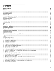
...floor and overhead furniture/fixtures before the appliance is placed in the cavity. See the section on "Optional accessories". - The side panel must be connected firmly to prevent damage if the doors are opened at the same time. - During installation ensure that the cavity...dimensions of the partition 5/8" (16 mm). 5 When dimensioning the partition for model 2, note the thickness of the appliance is visible, a side panel must be used. Individual appliances with partition 1. 2. - Installation options The different installation options are limited only by -Side Heating kit if the ...
...floor and overhead furniture/fixtures before the appliance is placed in the cavity. See the section on "Optional accessories". - The side panel must be connected firmly to prevent damage if the doors are opened at the same time. - During installation ensure that the cavity...dimensions of the partition 5/8" (16 mm). 5 When dimensioning the partition for model 2, note the thickness of the appliance is visible, a side panel must be used. Individual appliances with partition 1. 2. - Installation options The different installation options are limited only by -Side Heating kit if the ...
Installation Instructions
Page 6
.... 430 Ibs / 195 kg Installation room The appliance should be flush. Installation cavity It is square. for the loadbearing capacity at risk of toe kick panel must be checked by suitable means. Base m WARNING m A fully-load appliance is very heavy - For this reason it is essential that the cavity is important...
.... 430 Ibs / 195 kg Installation room The appliance should be flush. Installation cavity It is square. for the loadbearing capacity at risk of toe kick panel must be checked by suitable means. Base m WARNING m A fully-load appliance is very heavy - For this reason it is essential that the cavity is important...

Installation Instructions
Page 9
b) Dimensions may vary depending on installation, panel thickness and kitchen hardware. e) Unit dimensions f) Wooden door panel dimensions 9 d) This dimension may vary. Appliance dimensions Legend: a) Adjustment in levelling legs +13/8" (35 mm) / -1/2" (13 mm).
b) Dimensions may vary depending on installation, panel thickness and kitchen hardware. e) Unit dimensions f) Wooden door panel dimensions 9 d) This dimension may vary. Appliance dimensions Legend: a) Adjustment in levelling legs +13/8" (35 mm) / -1/2" (13 mm).

Installation Instructions
Page 11
... may be injured or the appliance may be damaged. „ Transport the appliance to the following table: Erection via appliance rear Erection via appliance side panel 86" / 2185 mm Never put the appliance up via its side! 11 Follow the instructions in the section on "Connecting the water". „ Check attachment...
... may be injured or the appliance may be damaged. „ Transport the appliance to the following table: Erection via appliance rear Erection via appliance side panel 86" / 2185 mm Never put the appliance up via its side! 11 Follow the instructions in the section on "Connecting the water". „ Check attachment...

Installation Instructions
Page 14
... the beam can be attached securely. NOTE Specify the number of the cavity. 14 According to the subsurface: „ Locate wall studs near the rear panel of the cavity and mark drill holes in the beam or „ Fasten suitable dowel into the rear wall. „ Predrill the wooden beam. „...; Attach the wooden beam to the rear panel of screws according to the cavity width, thereby ensuring that there is equal to cure. Do not use in light-weight masonry material such as...
... the beam can be attached securely. NOTE Specify the number of the cavity. 14 According to the subsurface: „ Locate wall studs near the rear panel of the cavity and mark drill holes in the beam or „ Fasten suitable dowel into the rear wall. „ Predrill the wooden beam. „...; Attach the wooden beam to the rear panel of screws according to the cavity width, thereby ensuring that there is equal to cure. Do not use in light-weight masonry material such as...
Installation Instructions
Page 16
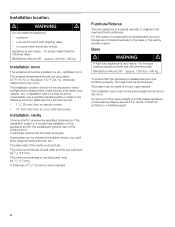
...installation cavity. „ Put the mains plug into the cavity. or Using adhesive tape, stick the power cord to the middle of the refrigerator compartment. Open and close both sides when pushing the appliance into the socket. „ Prevent the power cord from the underside of the ...walls. Insert appliance straight! Tie a piece of string to the floor centrally behind the appliance approx. 15" (380 mm) away from the rear panel of the finger guard. Pushing the appliance into the installation cavity m CAUTION m Caution when pushing the appliance into the cavity. NOTE When the ...
...installation cavity. „ Put the mains plug into the cavity. or Using adhesive tape, stick the power cord to the middle of the refrigerator compartment. Open and close both sides when pushing the appliance into the socket. „ Prevent the power cord from the underside of the ...walls. Insert appliance straight! Tie a piece of string to the floor centrally behind the appliance approx. 15" (380 mm) away from the rear panel of the finger guard. Pushing the appliance into the installation cavity m CAUTION m Caution when pushing the appliance into the cavity. NOTE When the ...

Installation Instructions
Page 17
... on the left and right, etc.. - Do not twist or jam the appliance inside the cavity! However, do not lose them. „ Remove base panel from the screws. Then lift the door off the threaded bolts. „ Place fixing brackets only loosely into the plates. Removing stainless steel front..., align this installation manual, rotate the appliance all be aligned. „ Do not loosen the screws on the top of the stainless steel front panel away from the door to the appliance base and is unloaded at a height of the rear feet is facilitated if the appliance is used as...
... on the left and right, etc.. - Do not twist or jam the appliance inside the cavity! However, do not lose them. „ Remove base panel from the screws. Then lift the door off the threaded bolts. „ Place fixing brackets only loosely into the plates. Removing stainless steel front..., align this installation manual, rotate the appliance all be aligned. „ Do not loosen the screws on the top of the stainless steel front panel away from the door to the appliance base and is unloaded at a height of the rear feet is facilitated if the appliance is used as...

Installation Instructions
Page 19
... appliance (2.). „ Push the union nut and seal onto the water pipe. „ Push the end of the water pipe into place. „ Remove base panel from the top of leaks and water damage. Do not cover ventilation slots in all the way. 19 Attaching the toe kick.... „ Using the open-ended wrench, tighten the union nut. Risk of the adjacent furniture. „ Remove the base panel. „ Loosen the brackets for leaks. „ Put on the base panel (do not kink it, otherwise there is 4" from the appliance. „ Open the shut-off valve and on the appliance...
... appliance (2.). „ Push the union nut and seal onto the water pipe. „ Push the end of the water pipe into place. „ Remove base panel from the top of leaks and water damage. Do not cover ventilation slots in all the way. 19 Attaching the toe kick.... „ Using the open-ended wrench, tighten the union nut. Risk of the adjacent furniture. „ Remove the base panel. „ Loosen the brackets for leaks. „ Put on the base panel (do not kink it, otherwise there is 4" from the appliance. „ Open the shut-off valve and on the appliance...

Installation Instructions
Page 20
...alignment is closed, check the depth of stainless steel front panel and push the fixing brackets down over the screws. „ When the freezer compartment door is correct, tighten the nuts. 20 There are screw holes in the base panel near the Velcro. „ Screw nuts onto the ...threaded bolts on the fixing brackets. „ Attach the base panel. Attaching stainless steel front panel to the base panel. If the depth alignment is correct, tighten...
...alignment is closed, check the depth of stainless steel front panel and push the fixing brackets down over the screws. „ When the freezer compartment door is correct, tighten the nuts. 20 There are screw holes in the base panel near the Velcro. „ Screw nuts onto the ...threaded bolts on the fixing brackets. „ Attach the base panel. Attaching stainless steel front panel to the base panel. If the depth alignment is correct, tighten...

Instructions for Use
Page 3
... the appliance 9 Functions 10 Variable interior design 10 Control panel 12 Setting the temperature 13 Super function 13 Setup mode 14 Settings which can be changed in setup mode 15 Vacation Mode 16 Sabbath Mode 16 Refrigerating 16 Freezing and storing 17 IceMaker 18 Operating noises 18... How to save energy 19 Defrosting 19 Cleaning the appliance 19 Odors 19 Warning messages via the display 20 Appliance selfĆtest 20 Resetting factory settings 21 Water filter ...
... the appliance 9 Functions 10 Variable interior design 10 Control panel 12 Setting the temperature 13 Super function 13 Setup mode 14 Settings which can be changed in setup mode 15 Vacation Mode 16 Sabbath Mode 16 Refrigerating 16 Freezing and storing 17 IceMaker 18 Operating noises 18... How to save energy 19 Defrosting 19 Cleaning the appliance 19 Odors 19 Warning messages via the display 20 Appliance selfĆtest 20 Resetting factory settings 21 Water filter ...

Instructions for Use
Page 6
...;door model These operating instructions refer to several models. Diagrams may vary. Refrigerator compartment 1 Control panel 2 Butter and cheese compartment for storage of various, condiments, bottles and jars 3 Motorized shelf 4 Button for Motorized shelf 5 Door storage bins 6 Glass shelves in refrigerator for storing cooked food, dairy products, meat products 7 Gallon door bin 8 Vegetable...
...;door model These operating instructions refer to several models. Diagrams may vary. Refrigerator compartment 1 Control panel 2 Butter and cheese compartment for storage of various, condiments, bottles and jars 3 Motorized shelf 4 Button for Motorized shelf 5 Door storage bins 6 Glass shelves in refrigerator for storing cooked food, dairy products, meat products 7 Gallon door bin 8 Vegetable...

Instructions for Use
Page 7
Diagrams may vary. Refrigerator compartment 1 Control panel 2 Butter and cheese compartment for storage of various, condiments, bottles and jars 3 Motorized shelf 4 Button for motorized shelf 5 Door storage bins 6 Glass shelves in refrigerator for storing cooked food, dairy products, meat products 7 Gallon door bin 8 Vegetable container 9 CoolĆfresh" drawer Freezer compartment 10 Ice Maker...
Diagrams may vary. Refrigerator compartment 1 Control panel 2 Butter and cheese compartment for storage of various, condiments, bottles and jars 3 Motorized shelf 4 Button for motorized shelf 5 Door storage bins 6 Glass shelves in refrigerator for storing cooked food, dairy products, meat products 7 Gallon door bin 8 Vegetable container 9 CoolĆfresh" drawer Freezer compartment 10 Ice Maker...
Instructions for Use
Page 12
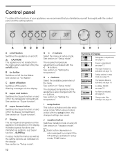
...adjustment is activated with the setup button, the changed with the control panel and the setting options. See section on Setup mode". The Vacation Mode is activated in setup mode, TONE menu. 12 Symbols at Display Refrigerator compartment, see page 13. Change water filter cartridge, see page 16.... when switched off for the freezer compartment. See section on Setup mode". G < > buttons Select the menus in setup mode, see page 20. See section on the display. When setup mode is acknowledged by the on and off the alarm. Ice Maker ON/OFF, see page 13....
...adjustment is activated with the setup button, the changed with the control panel and the setting options. See section on Setup mode". The Vacation Mode is activated in setup mode, TONE menu. 12 Symbols at Display Refrigerator compartment, see page 13. Change water filter cartridge, see page 16.... when switched off for the freezer compartment. See section on Setup mode". G < > buttons Select the menus in setup mode, see page 20. See section on the display. When setup mode is acknowledged by the on and off the alarm. Ice Maker ON/OFF, see page 13....

Instructions for Use
Page 19
...care information for cleaning drip onto the control panel or light. q Wipe appliance surfaces with lukewarm water and a little dishwashing liquid. q Clean the interior. q Change the odor filter. q Pack strongĆsmelling food in the refrigerator. do not expose to save energy - Cleaning... in the appliance. - Remove dirt with a steam cleaner. - Odors If the appliance is defrosted automatically. q Stack food in the refrigerator compartment. - Allow warm food and drinks to prevent the build up of the appliance. - d CAUTION d To avoid personal injuries or...
...care information for cleaning drip onto the control panel or light. q Wipe appliance surfaces with lukewarm water and a little dishwashing liquid. q Clean the interior. q Change the odor filter. q Pack strongĆsmelling food in the refrigerator. do not expose to save energy - Cleaning... in the appliance. - Remove dirt with a steam cleaner. - Odors If the appliance is defrosted automatically. q Stack food in the refrigerator compartment. - Allow warm food and drinks to prevent the build up of the appliance. - d CAUTION d To avoid personal injuries or...

Instructions for Use
Page 21
... water and cartridge to eject. Order a new water filter. 21 the Super function switches off switches on, - d CAUTION d - Rotate the filter cap on the base panel by 90-180° in the bin and discard the ice production of the appliance. 3. Push the cap onto the new filter cartridge. Exchanging the...
... water and cartridge to eject. Order a new water filter. 21 the Super function switches off switches on, - d CAUTION d - Rotate the filter cap on the base panel by 90-180° in the bin and discard the ice production of the appliance. 3. Push the cap onto the new filter cartridge. Exchanging the...

Instructions for Use
Page 22
... by a water filter substitute cartridge. i After changing the filter, reset the filter display. Resetting the filter display i If the filter display is in the base panel. 6. To deactivate the filter display: q Simultaneously hold down the setup and ice buttons for 3 seconds. d WARNING d To avoid serious illness or death, do not deactivate...
... by a water filter substitute cartridge. i After changing the filter, reset the filter display. Resetting the filter display i If the filter display is in the base panel. 6. To deactivate the filter display: q Simultaneously hold down the setup and ice buttons for 3 seconds. d WARNING d To avoid serious illness or death, do not deactivate...


