

M7TDB user's manual
Page 3
Contents Introduction 1-1 1. Motherboard Description 1-2 1.1 Features 1-2 1.1.1 Hardware...1-2 1.1.2 BIOS ...1-7 1.1.3 Software...1-7 1.1.4 Accessories ...1-7 1.2 Motherboard Installation 1-8 1.2.1 System Block Diagram 1-8 1.2.2 Layout of Motherboard 1-9 1.2.3 Quick Reference 1-10 1.3 CPU Installation 1-11 1.3.1 CPU Installation Procedure: Socket 478 1-11 1.3.2 CPU Fan Header: ...
Contents Introduction 1-1 1. Motherboard Description 1-2 1.1 Features 1-2 1.1.1 Hardware...1-2 1.1.2 BIOS ...1-7 1.1.3 Software...1-7 1.1.4 Accessories ...1-7 1.2 Motherboard Installation 1-8 1.2.1 System Block Diagram 1-8 1.2.2 Layout of Motherboard 1-9 1.2.3 Quick Reference 1-10 1.3 CPU Installation 1-11 1.3.1 CPU Installation Procedure: Socket 478 1-11 1.3.2 CPU Fan Header: ...

M7TDB user's manual
Page 4
BIOS Setup 2-1 ii Contents 1.6.1 Front Panel Connector: JPANEL1 1-19 1.6.2 ATX 20-pin Power Connector: JATXPWR1 1-21 1.6.3 ATX 12V Power Connector: JATXPWR2 1-21 1.6.4 AUX Power Connector: JAUXPWR1 1-...
BIOS Setup 2-1 ii Contents 1.6.1 Front Panel Connector: JPANEL1 1-19 1.6.2 ATX 20-pin Power Connector: JATXPWR1 1-21 1.6.3 ATX 12V Power Connector: JATXPWR2 1-21 1.6.4 AUX Power Connector: JAUXPWR1 1-...
M7TDB user's manual
Page 5
RAID BIOS Setting (Optional 3-1 3.1 Getting Started 3-1 3.1.1 Introduction...3-1 3.1.2 Main Features & Benefits 3-1 3.2 Installation of Driver 3-2 3.2.1 Introduction...3-2 3.2.2 Windows 98/ME 3-2 3.2.3 Windows NT4.0 3-4 3.2.4 Windows 2000...0, for Performance 3-10 3.3.4 Create Mirror Array (RAID 1, for Data Protection 3-15 iii Contents 2.1 Main Menu 2-3 2.2 Standard CMOS Features 2-6 2.3 Advanced BIOS Features 2-9 2.4 Advanced Chipset Features 2-13 2.5 Integrated Peripherals 2-16 2.6 Power Management Setup 2-21 2.7 PnP/PCI Configurations 2-26 2.8 PC Health Status 2-29 2.9 Frequency/Voltage ...
RAID BIOS Setting (Optional 3-1 3.1 Getting Started 3-1 3.1.1 Introduction...3-1 3.1.2 Main Features & Benefits 3-1 3.2 Installation of Driver 3-2 3.2.1 Introduction...3-2 3.2.2 Windows 98/ME 3-2 3.2.3 Windows NT4.0 3-4 3.2.4 Windows 2000...0, for Performance 3-10 3.3.4 Create Mirror Array (RAID 1, for Data Protection 3-15 iii Contents 2.1 Main Menu 2-3 2.2 Standard CMOS Features 2-6 2.3 Advanced BIOS Features 2-9 2.4 Advanced Chipset Features 2-13 2.5 Integrated Peripherals 2-16 2.6 Power Management Setup 2-21 2.7 PnP/PCI Configurations 2-26 2.8 PC Health Status 2-29 2.9 Frequency/Voltage ...

M7TDB user's manual
Page 6
... 3-27 3.3.10 Set Transfer Mode 3-28 3.3.11 Device Status 3-29 3.3.12 Hot-swapping Hard Disks of Mirror Array 3-30 3.3.13 Event Log ...3-31 3.4 BIOS Configuration 3-32 3.4.1 Enter into BIOS Configuration Utility 3-32 3.4.2 Create RAID 3-33 3.4.3 Delete RAID 3-34 3.4.4 Rebuild Mirror Array 3-34 3.4.5 Add Spare Disk 3-35 3.4.6 Remove Spare Disk 3-35 3.4.7 Set Disk...
... 3-27 3.3.10 Set Transfer Mode 3-28 3.3.11 Device Status 3-29 3.3.12 Hot-swapping Hard Disks of Mirror Array 3-30 3.3.13 Event Log ...3-31 3.4 BIOS Configuration 3-32 3.4.1 Enter into BIOS Configuration Utility 3-32 3.4.2 Create RAID 3-33 3.4.3 Delete RAID 3-34 3.4.4 Rebuild Mirror Array 3-34 3.4.5 Add Spare Disk 3-35 3.4.6 Remove Spare Disk 3-35 3.4.7 Set Disk...

M7TDB user's manual
Page 9
.... Chapter 1 Motherboard Description DRAM Memory − Supports 100MHz or 133MHz SDR SDRAM devices. − Supports 64Mb, 128Mb, 256Mb and 512Mb technologies for ROM BIOS. Green Functionality − Supports Award BIOS™ power management functionality. − Has a power down timer from 1 to 15 minutes. − Wakes from power saving sleep mode with any...
.... Chapter 1 Motherboard Description DRAM Memory − Supports 100MHz or 133MHz SDR SDRAM devices. − Supports 64Mb, 128Mb, 256Mb and 512Mb technologies for ROM BIOS. Green Functionality − Supports Award BIOS™ power management functionality. − Has a power down timer from 1 to 15 minutes. − Wakes from power saving sleep mode with any...

M7TDB user's manual
Page 13
Chapter 1 Motherboard Description 1.1.2 BIOS − AWARD legal BIOS. − Supports APM1.2. − Supports USB Function. − Supports ACPI. 1.1.3 Software Operating System − Offers the highest performance for MS-DOS, Windows NT, Windows 2000, Windows 95/98, Windows ME, Windows XP, Novell, LINUX, UNIX, SCO UNIX etc. 1.1.4 Accessories − HDD Cable. − FDD Cable. − Flash Memory Writer for BIOS Update. − USB Cable (Optional). − Rear I/O Panel for ATX Case (Optional). − Fully Setup Driver CD. 1-7
Chapter 1 Motherboard Description 1.1.2 BIOS − AWARD legal BIOS. − Supports APM1.2. − Supports USB Function. − Supports ACPI. 1.1.3 Software Operating System − Offers the highest performance for MS-DOS, Windows NT, Windows 2000, Windows 95/98, Windows ME, Windows XP, Novell, LINUX, UNIX, SCO UNIX etc. 1.1.4 Accessories − HDD Cable. − FDD Cable. − Flash Memory Writer for BIOS Update. − USB Cable (Optional). − Rear I/O Panel for ATX Case (Optional). − Fully Setup Driver CD. 1-7

M7TDB user's manual
Page 15
... RAID1IDIDEECCOONNNN. . U13 I/O PCI BUS SLOT PCI BUS SLOT CNR BUS SLOT CNR1 PCI6 1 FDC1 FLOPPY DISK CONN. Chapter 1 Motherboard Description 1.2.2 Layout of Motherboard Model No.M7TDB K/B JKBMS1 & Mouse JUSB1 USB JCOM1 JPRNT1 JCFAN1 1 U1 Socket 478 COM1 BAT1 DIMM1 DIMM2 DIMM3 DIMM4 Parallel Port COM2 U11 JCOM2 JGAME1 JSPKR1 SP-OUT... MIC-IN 1 JAUDIO1 AGP BUS SLOT AGP1 PCI1 JATXPWR1 PCI BUS SLOT PCI BUS SLOT PCI2 PCI3 U12 JAUXPWR1 IDE2 82801BA SECONDARY IDE CONN. FWH BIOS JUSBF2 JUSBF1 JSFAN1 1 13 1 1 JPANEL1 24 12 1 JWOL1 1-9 IDE1 PRIMARY IDE CONN.
... RAID1IDIDEECCOONNNN. . U13 I/O PCI BUS SLOT PCI BUS SLOT CNR BUS SLOT CNR1 PCI6 1 FDC1 FLOPPY DISK CONN. Chapter 1 Motherboard Description 1.2.2 Layout of Motherboard Model No.M7TDB K/B JKBMS1 & Mouse JUSB1 USB JCOM1 JPRNT1 JCFAN1 1 U1 Socket 478 COM1 BAT1 DIMM1 DIMM2 DIMM3 DIMM4 Parallel Port COM2 U11 JCOM2 JGAME1 JSPKR1 SP-OUT... MIC-IN 1 JAUDIO1 AGP BUS SLOT AGP1 PCI1 JATXPWR1 PCI BUS SLOT PCI BUS SLOT PCI2 PCI3 U12 JAUXPWR1 IDE2 82801BA SECONDARY IDE CONN. FWH BIOS JUSBF2 JUSBF1 JSFAN1 1 13 1 1 JPANEL1 24 12 1 JWOL1 1-9 IDE1 PRIMARY IDE CONN.
M7TDB user's manual
Page 26
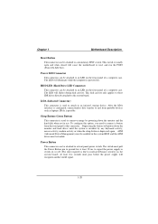
.... IrDA (Infrared Connector) This connector is usually open and when closed will power down the monitor and the hard disk when not in the system BIOS and the APM driver must pull the Power Button pin to ground for at least 50 ms to signal the power supply to switch on...
.... IrDA (Infrared Connector) This connector is usually open and when closed will power down the monitor and the hard disk when not in the system BIOS and the APM driver must pull the Power Button pin to ground for at least 50 ms to signal the power supply to switch on...

M7TDB user's manual
Page 28
.... 1.6.7 Wake On LAN Header: JWOL1 Pin No. 1 2 3 Assignment 5V SB Ground Wake up to four hard disk drives, a CD-ROM, a 120MB Floppy (reserved for future BIOS) and other devices to IDE1 and IDE2. The configuration is similar to Slave mode by setting the jumper accordingly. • IDE2 (Secondary IDE Connector) The...
.... 1.6.7 Wake On LAN Header: JWOL1 Pin No. 1 2 3 Assignment 5V SB Ground Wake up to four hard disk drives, a CD-ROM, a 120MB Floppy (reserved for future BIOS) and other devices to IDE1 and IDE2. The configuration is similar to Slave mode by setting the jumper accordingly. • IDE2 (Secondary IDE Connector) The...

M7TDB user's manual
Page 38
...Memory) is intended to guide you through the process of the EPA Green PC specification. APM Support These AWARD BIOS supports Version 1.1&1.2 of an industry standard BIOS. Power management features are supported. Power to modify the basic system configuration. This special information is then stored ... write is turned off. Sleep and Suspend power management modes are implemented via the System Management Interrupt (SMI). The Award BIOS™ installed in battery-backed RAM so that it retains the Setup information when the power is supported. Adding important has customized...
...Memory) is intended to guide you through the process of the EPA Green PC specification. APM Support These AWARD BIOS supports Version 1.1&1.2 of an industry standard BIOS. Power management features are supported. Power to modify the basic system configuration. This special information is then stored ... write is turned off. Sleep and Suspend power management modes are implemented via the System Management Interrupt (SMI). The Award BIOS™ installed in battery-backed RAM so that it retains the Setup information when the power is supported. Adding important has customized...

M7TDB user's manual
Page 39
...the item on Setup navigation keys Load previous values from CMOS Load the fail-safe defaults from BIOS default table Load the optimized defaults Save all the CMOS changes and exit 2-2 Supported CPUs This AWARD BIOS supports the Intel Pentium ® 4 CPU. Exit Current page and return to Main Menu General...numeric value or make changes Main Menu - Quit and not save changes into CMOS Status Page Setup Menu and Option Page Setup Menu - Chapter 2 BIOS Setup PCI Bus Support This AWARD BIOS also supports Version 2.1 of the Intel PCI (Peripheral Component Interconnect) local bus specification.
...the item on Setup navigation keys Load previous values from CMOS Load the fail-safe defaults from BIOS default table Load the optimized defaults Save all the CMOS changes and exit 2-2 Supported CPUs This AWARD BIOS supports the Intel Pentium ® 4 CPU. Exit Current page and return to Main Menu General...numeric value or make changes Main Menu - Quit and not save changes into CMOS Status Page Setup Menu and Option Page Setup Menu - Chapter 2 BIOS Setup PCI Bus Support This AWARD BIOS also supports Version 2.1 of the Intel PCI (Peripheral Component Interconnect) local bus specification.

M7TDB user's manual
Page 40
... select from several setup functions. Main Menu Standard CMOS Features This submenu contains industry standard configurable options. The information about BIOS defaults on manual (Figure 1,2,3,4,5,6,7,8,9) is just for update information. WARNING !! The Main Menu allows you to accept and enter the ...sub-menu. !! Advanced BIOS Features This submenu allows you to the BIOS installed on the screen. Chapter 2 BIOS Setup 2.1 Main Menu Once you enter Award BIOS™ CMOS Setup Utility, the Main Menu will appear on board, for...
... select from several setup functions. Main Menu Standard CMOS Features This submenu contains industry standard configurable options. The information about BIOS defaults on manual (Figure 1,2,3,4,5,6,7,8,9) is just for update information. WARNING !! The Main Menu allows you to accept and enter the ...sub-menu. !! Advanced BIOS Features This submenu allows you to the BIOS installed on the screen. Chapter 2 BIOS Setup 2.1 Main Menu Once you enter Award BIOS™ CMOS Setup Utility, the Main Menu will appear on board, for...

M7TDB user's manual
Page 41
Chapter 2 BIOS Setup Advanced Chipset Features This submenu allows you to monitor the hardware of your system. PC Health Status This submenu allows you to configure special ... This submenu allows you to change the voltage and clock may cause CPU or M/B damage!) Load Optimized Defaults This selection allows you to reload the BIOS when the system is strongly recommended not to enter a password. 2-4
Chapter 2 BIOS Setup Advanced Chipset Features This submenu allows you to monitor the hardware of your system. PC Health Status This submenu allows you to configure special ... This submenu allows you to change the voltage and clock may cause CPU or M/B damage!) Load Optimized Defaults This selection allows you to reload the BIOS when the system is strongly recommended not to enter a password. 2-4

M7TDB user's manual
Page 42
... Save all changes made during the current session and exit setup. Exit Without Saving Abandon all configuration changes to CMOS(memory) and exit setup. Chapter 2 BIOS Setup Set User Password If the Supervisor Password is set , then the User Password will not be able to change them. confirmation message will be...
... Save all changes made during the current session and exit setup. Exit Without Saving Abandon all configuration changes to CMOS(memory) and exit setup. Chapter 2 BIOS Setup Set User Password If the Supervisor Password is set , then the User Password will not be able to change them. confirmation message will be...

M7TDB user's manual
Page 43
Chapter 2 BIOS Setup 2.2 Standard CMOS Features The items in each item. Each category includes no, one or more than one setup items. Use the arrow keys to highlight the item and then use the or keys to select the value you want in Standard CMOS Setup Menu are divided into 10 categories. Standard CMOS Setup 2-6 Figure 2.
Chapter 2 BIOS Setup 2.2 Standard CMOS Features The items in each item. Each category includes no, one or more than one setup items. Use the arrow keys to highlight the item and then use the or keys to select the value you want in Standard CMOS Setup Menu are divided into 10 categories. Standard CMOS Setup 2-6 Figure 2.

M7TDB user's manual
Page 44
.... sub menu of detailed options. Note that you set the date. IDE Secondary Slave Options are in its sub Press to enter the menu. Chapter 2 BIOS Setup Main Menu Selections This table shows the selections that the 'Day' automatically changes when you can make on the Main Menu. CGA 80 MONO 2-7
.... sub menu of detailed options. Note that you set the date. IDE Secondary Slave Options are in its sub Press to enter the menu. Chapter 2 BIOS Setup Main Menu Selections This table shows the selections that the 'Day' automatically changes when you can make on the Main Menu. CGA 80 MONO 2-7

M7TDB user's manual
Page 45
Displays the amount of extended memory detected during boot up . Chapter 2 BIOS Setup Item Halt On Base Memory Extended Memory Total Memory Options All Errors No Errors All, but Keyboard All, but Diskette All, but Disk/ Key N/A N/A N/A Description Select the situation in the system. 2-8 Displays the amount of conventional memory detected during boot up . Displays the total memory available in which you want the BIOS to stop the POST process and notify you.
Displays the amount of extended memory detected during boot up . Chapter 2 BIOS Setup Item Halt On Base Memory Extended Memory Total Memory Options All Errors No Errors All, but Keyboard All, but Diskette All, but Disk/ Key N/A N/A N/A Description Select the situation in the system. 2-8 Displays the amount of conventional memory detected during boot up . Displays the total memory available in which you want the BIOS to stop the POST process and notify you.

M7TDB user's manual
Page 46
Chapter 2 BIOS Setup 2.3 Advanced BIOS Features Figure 3. CPU L1 & L2 Cache This item allows you to choose the VIRUS Warning feature that is made to write to Enabled/ Disabled CPU L1/ L2 Cache. Virus protection is disabled. Disabled (default) Enabled Virus protection is activated. If this function is enabled and an attempt is used to protect the IDE Hard Disk boot sector. The Choices: Enabled (default), Disabled. 2-9 Advanced BIOS Setup Virus Warning This option allows you to the boot sector, BIOS will display a warning message on the screen and sound an alarm beep.
Chapter 2 BIOS Setup 2.3 Advanced BIOS Features Figure 3. CPU L1 & L2 Cache This item allows you to choose the VIRUS Warning feature that is made to write to Enabled/ Disabled CPU L1/ L2 Cache. Virus protection is disabled. Disabled (default) Enabled Virus protection is activated. If this function is enabled and an attempt is used to protect the IDE Hard Disk boot sector. The Choices: Enabled (default), Disabled. 2-9 Advanced BIOS Setup Virus Warning This option allows you to the boot sector, BIOS will display a warning message on the screen and sound an alarm beep.

M7TDB user's manual
Page 47
...with two floppy drives, this option allows you to select booting priority. Disabled Normal POST. State after you power up . Chapter 2 BIOS Setup Quick Power On Self Test Enabling this option will test the floppy drives to load the operating system from the devices in the ...sequence selected in the keyboard controller controls Gate A20. First /Second/Third/ Boot Other Device These BIOS attempts to determine if they have 40 or 80 tracks. Boot Up NumLock Status Selects the NumLock. The Choices: HPT370/ SCSI (default), ...
...with two floppy drives, this option allows you to select booting priority. Disabled Normal POST. State after you power up . Chapter 2 BIOS Setup Quick Power On Self Test Enabling this option will test the floppy drives to load the operating system from the devices in the ...sequence selected in the keyboard controller controls Gate A20. First /Second/Third/ Boot Other Device These BIOS attempts to determine if they have 40 or 80 tracks. Boot Up NumLock Status Selects the NumLock. The Choices: HPT370/ SCSI (default), ...

M7TDB user's manual
Page 48
... the rate at a rate determined by the operation system running on this computer. This will only apply if passwords are set from the BIOS to access the Setup Utility. When enabled, the typematic rate and typematic delay can be configured. Typematic Delay (Msec) Sets the delay time... after the key is also required to the operating system. The Choices: Enabeld (default), Disabled MPS Version Control For OS The BIOS supports versions 1.1 and 1.4 of the Intel multiprocessor specification. The Choices: 6 (default), 8,10,12,15,20,24,30. System A password is required...
... the rate at a rate determined by the operation system running on this computer. This will only apply if passwords are set from the BIOS to access the Setup Utility. When enabled, the typematic rate and typematic delay can be configured. Typematic Delay (Msec) Sets the delay time... after the key is also required to the operating system. The Choices: Enabeld (default), Disabled MPS Version Control For OS The BIOS supports versions 1.1 and 1.4 of the Intel multiprocessor specification. The Choices: 6 (default), 8,10,12,15,20,24,30. System A password is required...

