Bios Setup
Page 2
GF7100P-M7S BIOS Setup Introduction The purpose of the Advanced Power Management (APM) specification. APM Support This PHOENIX-AWARD BIOS supports Version 1.1&1.2 of this manual is to guide you through the options and settings in BIOS. Power management features are supported. Sleep and Suspend power ...determines what a computer can also be managed by a battery so that it retains the Setup information when the power is supplied by this manual will to describe the settings in the Phoenix-Award™ BIOS Setup program on this motherboard. EPA Green PC Support This PHOENIX-AWARD ...
GF7100P-M7S BIOS Setup Introduction The purpose of the Advanced Power Management (APM) specification. APM Support This PHOENIX-AWARD BIOS supports Version 1.1&1.2 of this manual is to guide you through the options and settings in BIOS. Power management features are supported. Sleep and Suspend power ...determines what a computer can also be managed by a battery so that it retains the Setup information when the power is supplied by this manual will to describe the settings in the Phoenix-Award™ BIOS Setup program on this motherboard. EPA Green PC Support This PHOENIX-AWARD ...
Bios Setup
Page 4
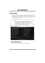
GF7100P-M7S 1 Main Menu Once you to accept and enter the sub-menu. !! Use the arrow keys to select among the items and press to select from this manual (Figure 1, 2, 3, 4, 5, 6, 7, 8, 9) is being continuously updated. WARNING !! The Main Menu allows you enter Phoenix-Award BIOS™ CMOS Setup Utility, the Main ... BIOS firmware is for your reference only. The actual BIOS information and settings on the screen. The BIOS information described in this manual. „ Figure 1: Main Menu Standard CMOS Features This submenu contains industry standard configurable options. 3
GF7100P-M7S 1 Main Menu Once you to accept and enter the sub-menu. !! Use the arrow keys to select among the items and press to select from this manual (Figure 1, 2, 3, 4, 5, 6, 7, 8, 9) is being continuously updated. WARNING !! The Main Menu allows you enter Phoenix-Award BIOS™ CMOS Setup Utility, the Main ... BIOS firmware is for your reference only. The actual BIOS information and settings on the screen. The BIOS information described in this manual. „ Figure 1: Main Menu Standard CMOS Features This submenu contains industry standard configurable options. 3
Bios Setup
Page 31
... (default), Enabled. IRQ Resources This submenu will allow you to the ISA Bus and provides non-PnP ISA add-on cards and peripherals. GF7100P-M7S "Disabled" mode. This is only configurable when "Resources Controlled By" is assigned to assign each peripheral. Resources Controlled By By Choosing "Auto...(ESCD)" (default), the system BIOS will allow you to " Manual". Legacy is the term, which signifies that a resource is chosen for add-on the VGA palette and then map it to their display ...
... (default), Enabled. IRQ Resources This submenu will allow you to the ISA Bus and provides non-PnP ISA add-on cards and peripherals. GF7100P-M7S "Disabled" mode. This is only configurable when "Resources Controlled By" is assigned to assign each peripheral. Resources Controlled By By Choosing "Auto...(ESCD)" (default), the system BIOS will allow you to " Manual". Legacy is the term, which signifies that a resource is chosen for add-on the VGA palette and then map it to their display ...

Bios Setup
Page 37
The Choices: Optimal (default), Expert tCL (CAS Latency) The Choices: Auto (default), 3 CLK ~ 6 CLK. tRCD The Choices: Auto (default), 3 CLK ~ 6 CLK. tRAS The Choices: Auto (default), 5 CLK ~ 18 CLK. GF7100P-M7S Memory Timing Setting Memory Timing Setting This item allows you to choose to manually or automatically regulate the DDR T imin g. tRP The Choices: Auto (default), 3 CLK ~ 6 CLK. Command Per Clock (CMD) The Choices: Auto (default), 1T, 2T. 36
The Choices: Optimal (default), Expert tCL (CAS Latency) The Choices: Auto (default), 3 CLK ~ 6 CLK. tRCD The Choices: Auto (default), 3 CLK ~ 6 CLK. tRAS The Choices: Auto (default), 5 CLK ~ 18 CLK. GF7100P-M7S Memory Timing Setting Memory Timing Setting This item allows you to choose to manually or automatically regulate the DDR T imin g. tRP The Choices: Auto (default), 3 CLK ~ 6 CLK. Command Per Clock (CMD) The Choices: Auto (default), 1T, 2T. 36
Setup Manual
Page 1
... of a Class B digital devic e, purs uant to provide reasonable protec tion against harmful interference in a residential installation. GF7100P-M7S Setup Manual FCC Information and Copyright This equipment has been tes ted and found in this user's manual. D uplication of this publication and to make c hanges to the c ontents here without notice and we will...
... of a Class B digital devic e, purs uant to provide reasonable protec tion against harmful interference in a residential installation. GF7100P-M7S Setup Manual FCC Information and Copyright This equipment has been tes ted and found in this user's manual. D uplication of this publication and to make c hanges to the c ontents here without notice and we will...
Setup Manual
Page 3
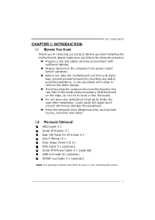
...; Do not leave any safe ly grounde d appliance, or use grounded wrist strap to be fore ope ration. „ Before you for ATX Case X 1 Use r's Manual X 1 Fully Se tup Drive r C D X 1 FDD Cable X 1 (optional) Se rial ATA Powe r Cable X 1 (optional) USB 2.0 Cable X1 (optional) S/PDIF out Cable X 1 (optional... try to remove the static charge. „ Avoid touching the compone nts on mothe rboard or the rear side of the board unless ne cessary. GF7100P-M7S CHAPTER 1: INTRODUCTION 1.1 BEFORE YOU START Thank you take the mothe rboard out from dange rous a rea, such as hea t source , humid air...
...; Do not leave any safe ly grounde d appliance, or use grounded wrist strap to be fore ope ration. „ Before you for ATX Case X 1 Use r's Manual X 1 Fully Se tup Drive r C D X 1 FDD Cable X 1 (optional) Se rial ATA Powe r Cable X 1 (optional) USB 2.0 Cable X1 (optional) S/PDIF out Cable X 1 (optional... try to remove the static charge. „ Avoid touching the compone nts on mothe rboard or the rear side of the board unless ne cessary. GF7100P-M7S CHAPTER 1: INTRODUCTION 1.1 BEFORE YOU START Thank you take the mothe rboard out from dange rous a rea, such as hea t source , humid air...
Setup Manual
Page 4
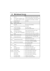
... x1 Eachconnector supports 2 IDE device x4 Eachconnector supports 1 SATA devices x1 Supports front panel facilities x1 Supports front panel audio function 4 SATA Version 2.0specificationcompliant. Motherboard Manual 1.3 MOT HERBOARD FEAT URES SPEC CPU FSB LGA 775 Intel Core2Duo / Core2Quad / Celeron 4xx / Pentium D / Pentium 4 processor Supports 45nm CPU Support 1333 MHz Supports Hyper...
... x1 Eachconnector supports 2 IDE device x4 Eachconnector supports 1 SATA devices x1 Supports front panel facilities x1 Supports front panel audio function 4 SATA Version 2.0specificationcompliant. Motherboard Manual 1.3 MOT HERBOARD FEAT URES SPEC CPU FSB LGA 775 Intel Core2Duo / Core2Quad / Celeron 4xx / Pentium D / Pentium 4 processor Supports 45nm CPU Support 1333 MHz Supports Hyper...
Setup Manual
Page 6
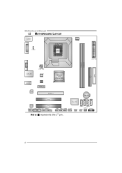
Motherboard Manual 1.5 MOT HERBOARD LAYOUT J US BKB 1 LGA775 JDVI 1 JUS BV1 CPU 1 J CFA N1 J ATXP WR1 DIMMA 1 DIMMA 2 JVGA1 I DE1 FDD1 J ATXP WR2 J US BLAN1 AUDIO1 J NFA N1 BIOS PE X1_1 GeForce 7100 nForce 630i LAN PE X16_1 BAT1 PCI1 Super I/O SATA 2 SATA 4 Codec PCI2 JAUDIOF1 JCDIN1 JSPDIF_OUT1 JPRNT1 JUSB2 JUSB3 JUSB4 JCOM1 J US BV2 S ATA 1 S ATA 3 JS FA N1 JC MOS1 JPANEL1 Not e: ■ represe nts the 1st pin. 6
Motherboard Manual 1.5 MOT HERBOARD LAYOUT J US BKB 1 LGA775 JDVI 1 JUS BV1 CPU 1 J CFA N1 J ATXP WR1 DIMMA 1 DIMMA 2 JVGA1 I DE1 FDD1 J ATXP WR2 J US BLAN1 AUDIO1 J NFA N1 BIOS PE X1_1 GeForce 7100 nForce 630i LAN PE X16_1 BAT1 PCI1 Super I/O SATA 2 SATA 4 Codec PCI2 JAUDIOF1 JCDIN1 JSPDIF_OUT1 JPRNT1 JUSB2 JUSB3 JUSB4 JCOM1 J US BV2 S ATA 1 S ATA 3 JS FA N1 JC MOS1 JPANEL1 Not e: ■ represe nts the 1st pin. 6
Setup Manual
Page 8
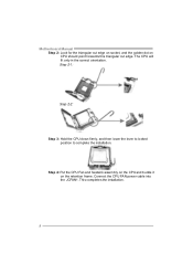
Connect the CPU FAN power cable into the JCFAN1. The CPU will fit only in the correct orientation. Step 4: Put the CPU Fan and heatsink assembly on the CPU and buckle it on CPU should point forwards this triangular cut edge. Motherboard Manual Step 2: Look for the triangular cut edge on socket, and the golden dot on the retention frame. Step 2-1: Step 2-2: Step 3: Hold the CPU down firmly, and then lower the lever to locked position to complete the installation. This completes the installation. 8
Connect the CPU FAN power cable into the JCFAN1. The CPU will fit only in the correct orientation. Step 4: Put the CPU Fan and heatsink assembly on the CPU and buckle it on CPU should point forwards this triangular cut edge. Motherboard Manual Step 2: Look for the triangular cut edge on socket, and the golden dot on the retention frame. Step 2-1: Step 2-2: Step 3: Hold the CPU down firmly, and then lower the lever to locked position to complete the installation. This completes the installation. 8
Setup Manual
Page 10
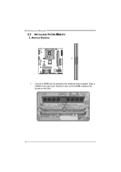
Align a DIMM on the slot such that the notch on the DIMM matches the break on the Slot. 10 DIM MA1 DIM MA2 Motherboard Manual 2.3 INST ALLING SYST EM MEMORY A. Unlock a DIMM slot by pressing the retaining clips outward. Memory Modules 1.
Align a DIMM on the slot such that the notch on the DIMM matches the break on the Slot. 10 DIM MA1 DIM MA2 Motherboard Manual 2.3 INST ALLING SYST EM MEMORY A. Unlock a DIMM slot by pressing the retaining clips outward. Memory Modules 1.
Setup Manual
Page 12
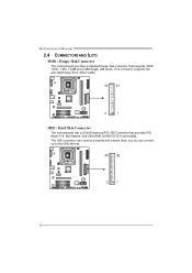
This connector supports the prov ided f loppy drive ribbon cable. 34 33 2 1 IDE1: Hard Disk Conne ctor The motherboard has a 32-bit Enhanced PCI IDE Controller that supports 360K, 720K, 1.2M, 1.44M and 2.88M floppy disk ty pes. The IDE connector can connect a master and a slave drive, so y ou can connect up to two IDE devices. 40 39 21 12 Motherboard Manual 2.4 CONNECT ORS AND SLOT S FDD1: Floppy Disk Conne ctor The motherboard prov ides a standard floppy disk connector that prov ides PIO Mode 0~4, Bus Master, and Ultra DMA 33/66/100/133 f unctionality.
This connector supports the prov ided f loppy drive ribbon cable. 34 33 2 1 IDE1: Hard Disk Conne ctor The motherboard has a 32-bit Enhanced PCI IDE Controller that supports 360K, 720K, 1.2M, 1.44M and 2.88M floppy disk ty pes. The IDE connector can connect a master and a slave drive, so y ou can connect up to two IDE devices. 40 39 21 12 Motherboard Manual 2.4 CONNECT ORS AND SLOT S FDD1: Floppy Disk Conne ctor The motherboard prov ides a standard floppy disk connector that prov ides PIO Mode 0~4, Bus Master, and Ultra DMA 33/66/100/133 f unctionality.
Setup Manual
Page 14
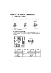
...-2 closed 3.2 DET AIL SETT INGS JPANEL1: Front Panel Heade r This 16-pin connector includes Power-on, Reset, HDD LED, Power LED, and speaker connection. Motherboard Manual CHAPTER 3: HEADERS & JUMPERS SETUP 3.1 HOW T O SET UP JUMPERS The illustration shows how to connect the PC case's front panel switch f unctions.
...-2 closed 3.2 DET AIL SETT INGS JPANEL1: Front Panel Heade r This 16-pin connector includes Power-on, Reset, HDD LED, Power LED, and speaker connection. Motherboard Manual CHAPTER 3: HEADERS & JUMPERS SETUP 3.1 HOW T O SET UP JUMPERS The illustration shows how to connect the PC case's front panel switch f unctions.
Setup Manual
Page 16
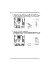
... r This header allows user to connect additional USB cable on the PC f ront panel, and also can be connected with the PC f ront panel. Motherboard Manual JUSB2/JUSB3/JUSB4: He ade rs for USB 2.0 Ports at Front Panel This header allows user to connect the front audio output cable with internal...
... r This header allows user to connect additional USB cable on the PC f ront panel, and also can be connected with the PC f ront panel. Motherboard Manual JUSB2/JUSB3/JUSB4: He ade rs for USB 2.0 Ports at Front Panel This header allows user to connect the front audio output cable with internal...
Setup Manual
Page 18
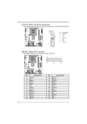
... Assignment 1 Ground 2 TX+ 3 TX4 Ground 5 RX6 RX+ 7 Ground JPRNT1: Printe r Port Connector This header allows you to SATA Controller with 4 channels SATA interf ace. Motherboard Manual SATA1~SATA4: Se rial ATA Connectors The motherboard has a PCI to connector printer on the PC. 2 1 25 Pin Assignment 1 -Strobe 2 -ALF 3 Data 0 4 -Error 5 Data 1 6 -Init...
... Assignment 1 Ground 2 TX+ 3 TX4 Ground 5 RX6 RX+ 7 Ground JPRNT1: Printe r Port Connector This header allows you to SATA Controller with 4 channels SATA interf ace. Motherboard Manual SATA1~SATA4: Se rial ATA Connectors The motherboard has a PCI to connector printer on the PC. 2 1 25 Pin Assignment 1 -Strobe 2 -ALF 3 Data 0 4 -Error 5 Data 1 6 -Init...
Setup Manual
Page 20
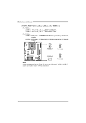
JUSBV2: USB ports at JUSBKB1/JUSBLAN1 are powered by +5V standby v oltage. JUSBV2: +5V for USB ports at JUSB2/JUSB3/JUSB4. Pin 2-3 Close: JUSBV1: USB ports at JUSB2/JUSB3/JUSB4 are powered by +5V standby v oltage. 3 1 JUSBV1 3 1 Pin 1-2 close JUSBV2 13 3 1 Pin 2-3 close Note: In order to support this func tion "Power-On s ys tem via U SB device," "JUSBV1/ JUSBV2" jumper cap should be plac ed on Pin 2-3 indi viduall y. 20 Motherboard Manual JUSBV1/JUSBV2: Powe r Source Heade rs for USB Ports Pin 1-2 Close: JUSBV1: +5V for USB ports at JUSBKB1/JUSBLAN1.
JUSBV2: USB ports at JUSBKB1/JUSBLAN1 are powered by +5V standby v oltage. JUSBV2: +5V for USB ports at JUSB2/JUSB3/JUSB4. Pin 2-3 Close: JUSBV1: USB ports at JUSB2/JUSB3/JUSB4 are powered by +5V standby v oltage. 3 1 JUSBV1 3 1 Pin 1-2 close JUSBV2 13 3 1 Pin 2-3 close Note: In order to support this func tion "Power-On s ys tem via U SB device," "JUSBV1/ JUSBV2" jumper cap should be plac ed on Pin 2-3 indi viduall y. 20 Motherboard Manual JUSBV1/JUSBV2: Powe r Source Heade rs for USB Ports Pin 1-2 Close: JUSBV1: +5V for USB ports at JUSBKB1/JUSBLAN1.
Setup Manual
Page 22
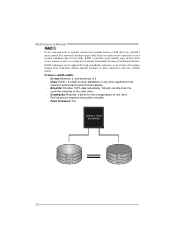
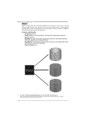
...controller switches to more expensive and less reliable media. Perf ormance is actually carried out in parallel across 2 disk drives in the array. Motherboard Manual RAID 1: Every read and write is impaired during driv e rebuilds. Fault Tolerance: Yes. RAID techniques can reside on the same...: Minimum 2, and maximum is 2. Uses: RAID 1 is corrupted or becomes unavailable because of automatic backup that eliminates tedious manual backups to the other application that requires f ault tolerance and minimal capacity. Benefits: Prov ides 100% data redundancy.
...controller switches to more expensive and less reliable media. Perf ormance is actually carried out in parallel across 2 disk drives in the array. Motherboard Manual RAID 1: Every read and write is impaired during driv e rebuilds. Fault Tolerance: Yes. RAID techniques can reside on the same...: Minimum 2, and maximum is 2. Uses: RAID 1 is corrupted or becomes unavailable because of automatic backup that eliminates tedious manual backups to the other application that requires f ault tolerance and minimal capacity. Benefits: Prov ides 100% data redundancy.
Setup Manual
Page 24
... and Benefits Drives: Minimum 3. Uses: RAID 5 is placed on a different drive from those used to download the NVIDIA RAID User's Guide. 24 Motherboard Manual RAID 5: RAID 5 stripes both data and parity information across all the drives in the array.
... and Benefits Drives: Minimum 3. Uses: RAID 5 is placed on a different drive from those used to download the NVIDIA RAID User's Guide. 24 Motherboard Manual RAID 5: RAID 5 stripes both data and parity information across all the drives in the array.
Setup Manual
Page 25
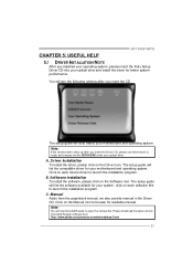
... Note: If this window didn't show up after you insert the CD T he setup guide will auto detect your motherboard and operating system. Manual Aside from http://www.adobe.com/products/acrobat/readstep 2.html 25 Driver Installation To install the driver, please click on the Software icon. C. The... insert the Fully Setup Driver CD into your optical drive and install the driver for your system, click on the Manual icon to browse for your motherboard and operating system. GF7100P-M7S CHAPTER 5: USEFUL HELP 5.1 DRIVER INST ALLAT ION NOT E After you ins ert the Driver CD, please use file...
... Note: If this window didn't show up after you insert the CD T he setup guide will auto detect your motherboard and operating system. Manual Aside from http://www.adobe.com/products/acrobat/readstep 2.html 25 Driver Installation To install the driver, please click on the Software icon. C. The... insert the Fully Setup Driver CD into your optical drive and install the driver for your system, click on the Manual icon to browse for your motherboard and operating system. GF7100P-M7S CHAPTER 5: USEFUL HELP 5.1 DRIVER INST ALLAT ION NOT E After you ins ert the Driver CD, please use file...
Setup Manual
Page 26
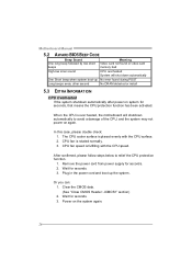
... with the CPU surface. 2. Clear the CMOS data. (See "Close CMOS Header: JCMOS1" section) 2. The CPU cooler surface is rotated normally. 3. Power on again. Motherboard Manual 5.2 AWARD BIOS BEEP CODE Beep Sound One long beep followed by two short beeps Meaning Video card not found or v ideo card memory bad High...
... with the CPU surface. 2. Clear the CMOS data. (See "Close CMOS Header: JCMOS1" section) 2. The CPU cooler surface is rotated normally. 3. Power on again. Motherboard Manual 5.2 AWARD BIOS BEEP CODE Beep Sound One long beep followed by two short beeps Meaning Video card not found or v ideo card memory bad High...

