
Setup Manual
Page 2
Table of Contents Chapter 1: Introduction 1 1.1 Before You Start 1 1.2 Package Checklist 1 1.3 Motherboard Features 2 1.4 Rear Panel Connectors 3 1.5 Motherboard Layout 4 Chapter 2: Hardware Installation 5 2.1 Installing Central Processing Unit (CPU 5 2.2 FAN Headers 7 2.3 Installing System Memory 8 2.4 Connectors and Slots 10 Chapter 3: Headers & Jumpers Setup 13 3.1 How to Setup Jumpers 13 3.2 Detail Settings 13 Chapter 4: Useful Help ...
Table of Contents Chapter 1: Introduction 1 1.1 Before You Start 1 1.2 Package Checklist 1 1.3 Motherboard Features 2 1.4 Rear Panel Connectors 3 1.5 Motherboard Layout 4 Chapter 2: Hardware Installation 5 2.1 Installing Central Processing Unit (CPU 5 2.2 FAN Headers 7 2.3 Installing System Memory 8 2.4 Connectors and Slots 10 Chapter 3: Headers & Jumpers Setup 13 3.1 How to Setup Jumpers 13 3.2 Detail Settings 13 Chapter 4: Useful Help ...
Setup Manual
Page 4
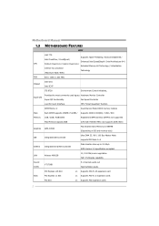
...OC) / 1066 / 800 Memory 1GB / 2GB / 4GB DDR3 Registered DIMM and ECC DIMM is not supported Max Memory Capacity 8GB (CPU with FSB 800 MHz only supports DDR3 800) Graphics GMA X4500 Max Shared Video Memory is 1984MB (Depending on OS and memory size)... MOTHERBOARD FEATURES SPEC LGA 775 Supports Hyper-Threading / Execute Disable Bit / Intel Core2Duo / Core2Quad / Enhanced Intel SpeedStep® / Intel Architecture-64 / CPU Pentium Dual-Core / Celeron Dual-Core / Extended Memory 64 Technology / Virtualization Celeron 4xx processor Technology (Maximum Watt: 95W) FSB 800 / 1066 / ...
...OC) / 1066 / 800 Memory 1GB / 2GB / 4GB DDR3 Registered DIMM and ECC DIMM is not supported Max Memory Capacity 8GB (CPU with FSB 800 MHz only supports DDR3 800) Graphics GMA X4500 Max Shared Video Memory is 1984MB (Depending on OS and memory size)... MOTHERBOARD FEATURES SPEC LGA 775 Supports Hyper-Threading / Execute Disable Bit / Intel Core2Duo / Core2Quad / Enhanced Intel SpeedStep® / Intel Architecture-64 / CPU Pentium Dual-Core / Celeron Dual-Core / Extended Memory 64 Technology / Virtualization Celeron 4xx processor Technology (Maximum Watt: 95W) FSB 800 / 1066 / ...
Setup Manual
Page 5
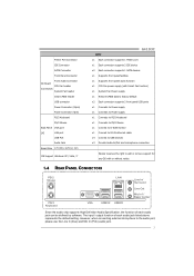
...Printer Port Connector IDE Connector SATA Connector Front Panel Connector Front Audio Connector On Board CPU Fan header Connectors System Fan header Clear CMOS header USB connector Power Connector (24pin) ... Port Audio Jack Board Size 170 (W) x 225 (L) mm OS Support Windows XP / Vista / 7 G41D3C SPEC x1 Each connector supports 1 Printer port x1 Each connector supports 2 IDE device x2 Each connector supports ...-45 ethernet cable x4 Connect to USB devices x3 Provide Audio-In/Out and microphone connection Biostar reserves the right to the audio port, please use the Line In (blue) and Mic...
...Printer Port Connector IDE Connector SATA Connector Front Panel Connector Front Audio Connector On Board CPU Fan header Connectors System Fan header Clear CMOS header USB connector Power Connector (24pin) ... Port Audio Jack Board Size 170 (W) x 225 (L) mm OS Support Windows XP / Vista / 7 G41D3C SPEC x1 Each connector supports 1 Printer port x1 Each connector supports 2 IDE device x2 Each connector supports ...-45 ethernet cable x4 Connect to USB devices x3 Provide Audio-In/Out and microphone connection Biostar reserves the right to the audio port, please use the Line In (blue) and Mic...
Setup Manual
Page 6
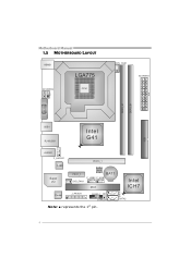
Motherboard Manual 1.5 MOTHERBOARD LAYOUT KBMS1 LGA775 ATX PW R2 CPU1 CPU _FA N1 ATX PW R1 D DR3_A 1 D DR3_B 1 VG A1 ID E1 USB1 RJ 45U SB 1 Intel G41 AU DIO1 F _AU DI O1 LAN Super I/O PEX16_1 PEX1_1 SYS_FAN1 BIOS BAT1 F_USB2 F_USB1 PCI1 Intel ICH7 SATA1 Codec J_PR INT 1 PAN EL1 JC MOS1 SATA2 Note: ■ represents the 1st pin. 4
Motherboard Manual 1.5 MOTHERBOARD LAYOUT KBMS1 LGA775 ATX PW R2 CPU1 CPU _FA N1 ATX PW R1 D DR3_A 1 D DR3_B 1 VG A1 ID E1 USB1 RJ 45U SB 1 Intel G41 AU DIO1 F _AU DI O1 LAN Super I/O PEX16_1 PEX1_1 SYS_FAN1 BIOS BAT1 F_USB2 F_USB1 PCI1 Intel ICH7 SATA1 Codec J_PR INT 1 PAN EL1 JC MOS1 SATA2 Note: ■ represents the 1st pin. 4
Setup Manual
Page 7
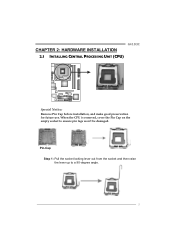
G41D3C CHAPTER 2: HARDWARE INSTALLATION 2.1 INSTALLING CENTRAL PROCESSING UNIT (CPU) Special Notice: Remove Pin Cap before installation, and make good preservation for future use. Pin-Cap Step 1: Pull the socket locking lever out from the socket and then raise the lever up to ensure pin legs won't be damaged. When the CPU is removed, cover the Pin Cap on the empty socket to a 90-degree angle. 5
G41D3C CHAPTER 2: HARDWARE INSTALLATION 2.1 INSTALLING CENTRAL PROCESSING UNIT (CPU) Special Notice: Remove Pin Cap before installation, and make good preservation for future use. Pin-Cap Step 1: Pull the socket locking lever out from the socket and then raise the lever up to ensure pin legs won't be damaged. When the CPU is removed, cover the Pin Cap on the empty socket to a 90-degree angle. 5
Setup Manual
Page 8
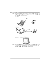
Step 2-1: Step 2-2: Step 3: Hold the CPU down firmly, and then lower the lever to locked position to complete the installation. Connect the CPU FAN power cable into the CPU_FAN1. This completes the installation. 6 Step 4: Put the CPU Fan and heatsink assembly on the CPU and buckle it on CPU should point forwards this triangular cut edge on socket, and the golden dot on the retention frame. Motherboard Manual Step 2: Look for the triangular cut edge. The CPU will fit only in the correct orientation.
Step 2-1: Step 2-2: Step 3: Hold the CPU down firmly, and then lower the lever to locked position to complete the installation. Connect the CPU FAN power cable into the CPU_FAN1. This completes the installation. 6 Step 4: Put the CPU Fan and heatsink assembly on the CPU and buckle it on CPU should point forwards this triangular cut edge on socket, and the golden dot on the retention frame. Motherboard Manual Step 2: Look for the triangular cut edge. The CPU will fit only in the correct orientation.
Setup Manual
Page 9
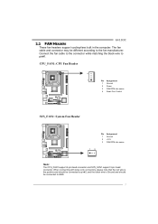
Connect the fan cable to the connector while matching the black wire to GND. 7 G41D3C 2.2 FAN HEADERS These fan headers support cooling-fans built in the computer. When connecting with wires onto connectors, please note that the red wire is ... the black wire is Ground and should be different according to the fan manufacturer. The fan cable and connector may be connected to pin#1. CPU_FAN1: CPU Fan Header 4 1 Pin Assignment 1 Ground 2 Power 3 FAN RPM rate sense 4 Smart Fan Control SYS_FAN1: System Fan Header Pin Assignment 1 Ground 2 +12V 3 FAN RPM rate sense...
Connect the fan cable to the connector while matching the black wire to GND. 7 G41D3C 2.2 FAN HEADERS These fan headers support cooling-fans built in the computer. When connecting with wires onto connectors, please note that the red wire is ... the black wire is Ground and should be different according to the fan manufacturer. The fan cable and connector may be connected to pin#1. CPU_FAN1: CPU Fan Header 4 1 Pin Assignment 1 Ground 2 Power 3 FAN RPM rate sense 4 Smart Fan Control SYS_FAN1: System Fan Header Pin Assignment 1 Ground 2 +12V 3 FAN RPM rate sense...
Setup Manual
Page 13
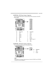
G41D3C ATXPWR1: ATX Power Source Connector This connector allows user to connect 24-pin power connector on the ATX power supply. 12 24 1 13 Pin Assignment ... 3 Ground 4 +5V 5 Ground 6 +5V 7 Ground 8 PW_OK 9 Standby Voltage+5V 10 +12V 11 +12V 12 +3.3V ATXPWR2: ATX Power Source Connector This connector provides +12V to CPU power circuit. 32 Pin Assignment 4 1 1 +12V 2 +12V 3 Ground 4 Ground Note: Before power on the system, please make sure that both ATXPWR1 and ATXPWR2 connectors have...
G41D3C ATXPWR1: ATX Power Source Connector This connector allows user to connect 24-pin power connector on the ATX power supply. 12 24 1 13 Pin Assignment ... 3 Ground 4 +5V 5 Ground 6 +5V 7 Ground 8 PW_OK 9 Standby Voltage+5V 10 +12V 11 +12V 12 +3.3V ATXPWR2: ATX Power Source Connector This connector provides +12V to CPU power circuit. 32 Pin Assignment 4 1 1 +12V 2 +12V 3 Ground 4 Ground Note: Before power on the system, please make sure that both ATXPWR1 and ATXPWR2 connectors have...
Setup Manual
Page 20
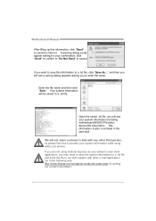
click "Send" to confirm or "Do Not Send" to the following web http://www.biostar.com.tw/app/en-us/about/contact.php for your default e-mail client application, you want to save the system information to a .txt file and ... file, click "Save As..." Your system information will see a saving dialog appears asking you will be saved to provide your system information including motherboard/BIOS/CPU/video/ device/OS information. If you are not using eHot-Line service. Enter the file name and then click "Save". Open the saved .txt file...
click "Send" to confirm or "Do Not Send" to the following web http://www.biostar.com.tw/app/en-us/about/contact.php for your default e-mail client application, you want to save the system information to a .txt file and ... file, click "Save As..." Your system information will see a saving dialog appears asking you will be saved to provide your system information including motherboard/BIOS/CPU/video/ device/OS information. If you are not using eHot-Line service. Enter the file name and then click "Save". Open the saved .txt file...
Setup Manual
Page 24
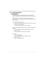
... Or you can: 1. When the CPU is fulfilling with the CPU surface. 2. CPU fan speed is over heated, the motherboard will shutdown automatically to relief the CPU protection function. 1. Wait for seconds. 3. Motherboard Manual 4.3 EXTRA INFORMATION CPU Overheated If the system shutdown automatically after... CMOS data. (See "Close CMOS Header: JCMOS1" section) 2. The CPU cooler surface is rotated normally. 3. Remove the power cord from power supply for seconds, that means the CPU protection function has been activated. After confirmed, please follow steps below to ...
... Or you can: 1. When the CPU is fulfilling with the CPU surface. 2. CPU fan speed is over heated, the motherboard will shutdown automatically to relief the CPU protection function. 1. Wait for seconds. 3. Motherboard Manual 4.3 EXTRA INFORMATION CPU Overheated If the system shutdown automatically after... CMOS data. (See "Close CMOS Header: JCMOS1" section) 2. The CPU cooler surface is rotated normally. 3. Remove the power cord from power supply for seconds, that means the CPU protection function has been activated. After confirmed, please follow steps below to ...
Bios Setup
Page 3
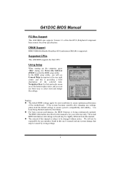
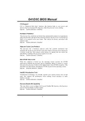
G41D3C BIOS Manual PCI Bus Support This AMI BIOS also supports Version 2.3 of the motherboard. Using Setup When starting up the computer, press during the Power-... right corner, and you will not be responsible for most conditions to be caused by wrong-settings. 2 Supported CPUs This AMI BIOS supports the Intel CPU. The actual BIOS information and settings on board may be changed without notice. Navigation Keys for your reference only. DRAM Support DDR3 SDRAM (Double Data...
G41D3C BIOS Manual PCI Bus Support This AMI BIOS also supports Version 2.3 of the motherboard. Using Setup When starting up the computer, press during the Power-... right corner, and you will not be responsible for most conditions to be caused by wrong-settings. 2 Supported CPUs This AMI BIOS supports the Intel CPU. The actual BIOS information and settings on board may be changed without notice. Navigation Keys for your reference only. DRAM Support DDR3 SDRAM (Double Data...
Bios Setup
Page 8
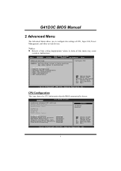
...Exit Advanced Settings WARNING: Setting wrong values in items of CPU, Super I/O, Power Management, and other system devices. Notice z Beware of that the BIOS automatically detects. CPU Configuration This item shows the CPU information that setting inappropriate values in below sections may cause ... [Enabled] Execute-Disable Bit Capability [Enabled] Core Multi-Processing [Enabled] Options Disabled Enabled Select Screen Select Item +- G41D3C BIOS Manual 2 Advanced Menu The Advanced Menu allows you to configure the settings of this menu may cause system to malfunction...
...Exit Advanced Settings WARNING: Setting wrong values in items of CPU, Super I/O, Power Management, and other system devices. Notice z Beware of that the BIOS automatically detects. CPU Configuration This item shows the CPU information that setting inappropriate values in below sections may cause ... [Enabled] Execute-Disable Bit Capability [Enabled] Core Multi-Processing [Enabled] Options Disabled Enabled Select Screen Select Item +- G41D3C BIOS Manual 2 Advanced Menu The Advanced Menu allows you to configure the settings of this menu may cause system to malfunction...
Bios Setup
Page 9
This reduces cache latency by lowering CPU frequency while the processor is booted up, the operating system executes the CPUID instruction to find out the highest input value CPUID recognizes. This determines ... can do so, it must first query the processor to identify the processor and its requirements and prefetches data and instructions from buffer overflow attacks. G41D3C BIOS Manual C1E Support C1E is "Enhanced Halt State" function, this function helps to configure the Execute Disabled Bit function, which protects your system resource...
This reduces cache latency by lowering CPU frequency while the processor is booted up, the operating system executes the CPUID instruction to find out the highest input value CPUID recognizes. This determines ... can do so, it must first query the processor to identify the processor and its requirements and prefetches data and instructions from buffer overflow attacks. G41D3C BIOS Manual C1E Support C1E is "Enhanced Halt State" function, this function helps to configure the Execute Disabled Bit function, which protects your system resource...
Bios Setup
Page 12
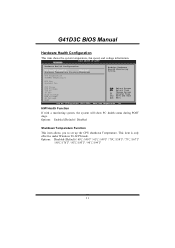
...Option F1 General Help F10 Save and Exit ESC Exit vxx.xx (C)Copyright 1985-200x, American Megatrends, Inc. CPU Temperature SYSTEM Temperature CPU Fan System1 Fan CPU Vcore DDR Voltage +12.0V +5.00V Chip Voltage FSB Voltage SB Voltage 5BSV Select Screen Select Item +- Advanced...70℃/158℉ / 75℃/167℉ / 80℃/176℉ / 85℃/185℉ / 90℃/194℉ 11 G41D3C BIOS Manual Hardware Health Configuration This item shows the system temperature, fan speed, and voltage information. Options: Enabled (Default) / Disabled Shutdown Temperature Function ...
...Option F1 General Help F10 Save and Exit ESC Exit vxx.xx (C)Copyright 1985-200x, American Megatrends, Inc. CPU Temperature SYSTEM Temperature CPU Fan System1 Fan CPU Vcore DDR Voltage +12.0V +5.00V Chip Voltage FSB Voltage SB Voltage 5BSV Select Screen Select Item +- Advanced...70℃/158℉ / 75℃/167℉ / 80℃/176℉ / 85℃/185℉ / 90℃/194℉ 11 G41D3C BIOS Manual Hardware Health Configuration This item shows the system temperature, fan speed, and voltage information. Options: Enabled (Default) / Disabled Shutdown Temperature Function ...
Bios Setup
Page 13
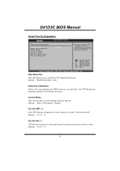
... 1985-200x, American Megatrends, Inc. Options: Quiet / Performance / Manual Fan Ctrl OFF(℃) If the CPU/System Temperature is lower than the set value. G41D3C BIOS Manual Smart Fan Configuration Advanced BIOS SETUP UTILITY Smart Fan Configuration CPU Smart Fan Smart Fan Calibration Control Mode Fan Ctrl OFF(oC) Fan Ctrl On(oC...
... 1985-200x, American Megatrends, Inc. Options: Quiet / Performance / Manual Fan Ctrl OFF(℃) If the CPU/System Temperature is lower than the set value. G41D3C BIOS Manual Smart Fan Configuration Advanced BIOS SETUP UTILITY Smart Fan Configuration CPU Smart Fan Smart Fan Calibration Control Mode Fan Ctrl OFF(oC) Fan Ctrl On(oC...
Bios Setup
Page 14
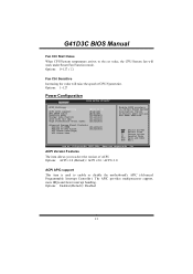
... 13 Options: 0~127 (℃) Fan Ctrl Sensitive Increasing the value will work under Smart Fan Function mode. G41D3C BIOS Manual Fan Ctrl Start Value When CPU/System temperature arrives to select the version of CPU/System fan. The APIC provides multiprocessor support, more IRQs and faster interrupt handling. ACPI Version Features The item...
... 13 Options: 0~127 (℃) Fan Ctrl Sensitive Increasing the value will work under Smart Fan Function mode. G41D3C BIOS Manual Fan Ctrl Start Value When CPU/System temperature arrives to select the version of CPU/System fan. The APIC provides multiprocessor support, more IRQs and faster interrupt handling. ACPI Version Features The item...
Bios Setup
Page 18
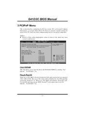
G41D3C BIOS Manual 3 PCIPnP Menu This section describes configuring the PCI bus system. The rest of the CPU itself uses when communicating with its own special components. For non-PnP operating systems (DOS, Netware™ ), this menu may cause system to operate at ...
G41D3C BIOS Manual 3 PCIPnP Menu This section describes configuring the PCI bus system. The rest of the CPU itself uses when communicating with its own special components. For non-PnP operating systems (DOS, Netware™ ), this menu may cause system to operate at ...
Bios Setup
Page 28
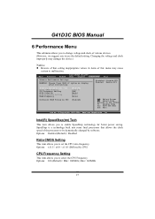
..., Inc. Disabled: Disable GV3 Enabled: Enable GV3 Intel(R) SpeedStep(tm) tech Ratio CMOS Setting CPU Frequency Setting PCIE Clock By PCIE Frequency Setting DRAM Frequency Configure DRAM Timing by CPU) CPU Frequency Setting This item allows you to use the default setting. Intel(R) SpeedStep(tm) Tech This.... Options: Enabled (Default) / Disabled Ratio CMOS Setting This item allows you to enable SpeedStep technology for better power saving. G41D3C BIOS Manual 6 Performance Menu This submenu allows you to change voltage and clock of various devices. (However, we suggest you to select ...
..., Inc. Disabled: Disable GV3 Enabled: Enable GV3 Intel(R) SpeedStep(tm) tech Ratio CMOS Setting CPU Frequency Setting PCIE Clock By PCIE Frequency Setting DRAM Frequency Configure DRAM Timing by CPU) CPU Frequency Setting This item allows you to use the default setting. Intel(R) SpeedStep(tm) Tech This.... Options: Enabled (Default) / Disabled Ratio CMOS Setting This item allows you to enable SpeedStep technology for better power saving. G41D3C BIOS Manual 6 Performance Menu This submenu allows you to change voltage and clock of various devices. (However, we suggest you to select ...


