Setup Manual
Page 1
... without notice and we will not occur in a particular installation. These limits are trademarks of the FCC Rules. Duplication of this user's manual is subject to provide reasonable protection against harmful interference in a residential installation. Further the vendor reserves the right to revise this publication and...warranties with the instructions, may cause harmful interference to notify any purpose. There is not allowed without obligation to radio communications. G41 HD Setup Manual FCC Information and Copyright This equipment has been tested and found in this user...
... without notice and we will not occur in a particular installation. These limits are trademarks of the FCC Rules. Duplication of this user's manual is subject to provide reasonable protection against harmful interference in a residential installation. Further the vendor reserves the right to revise this publication and...warranties with the instructions, may cause harmful interference to notify any purpose. There is not allowed without obligation to radio communications. G41 HD Setup Manual FCC Information and Copyright This equipment has been tested and found in this user...

Setup Manual
Page 3
...from power outlet before operation. „ Before you for ATX Case X 1 Installation Guide X 1 Fully Setup Driver CD X 1 (full version manual files inside the case after installation. Loose parts will cause short circuits which may damage the equipment. „ Keep the computer from dangerous area,...132; Do not leave any safely grounded appliance, or use grounded wrist strap to area or your motherboard version. 1 CHAPTER 1: INTRODUCTION G41 HD 1.1 BEFORE YOU START Thank you take the motherboard out from anti-static bag, ground yourself properly by touching any unfastened small parts ...
...from power outlet before operation. „ Before you for ATX Case X 1 Installation Guide X 1 Fully Setup Driver CD X 1 (full version manual files inside the case after installation. Loose parts will cause short circuits which may damage the equipment. „ Keep the computer from dangerous area,...132; Do not leave any safely grounded appliance, or use grounded wrist strap to area or your motherboard version. 1 CHAPTER 1: INTRODUCTION G41 HD 1.1 BEFORE YOU START Thank you take the motherboard out from anti-static bag, ground yourself properly by touching any unfastened small parts ...

Setup Manual
Page 4
... Supports PCI expansion cards x1 Supports PCI-E x16 expansion card x1 Each connector supports 1 Printer port x1 Connects to 3.0 Gb/s. Motherboard Manual 1.3 MOTHERBOARD FEATURES SPEC LGA 775 Intel Core2Duo / Core2Quad / Supports Execute Disable Bit / Enhanced Intel CPU Pentium Dual-Core / Celeron ... Memory 64 Technology / Virtualization Technology (Maximum Watt: 95W) FSB Support 800 / 1066 / 1333 MHz Chipset Intel G41 Intel ICH7 ITE 8721 Environment Control initiatives, Provides the most commonly used legacy Hardware Monitor Controller Super I/O Super I/O functionality.
... Supports PCI expansion cards x1 Supports PCI-E x16 expansion card x1 Each connector supports 1 Printer port x1 Connects to 3.0 Gb/s. Motherboard Manual 1.3 MOTHERBOARD FEATURES SPEC LGA 775 Intel Core2Duo / Core2Quad / Supports Execute Disable Bit / Enhanced Intel CPU Pentium Dual-Core / Celeron ... Memory 64 Technology / Virtualization Technology (Maximum Watt: 95W) FSB Support 800 / 1066 / 1333 MHz Chipset Intel G41 Intel ICH7 ITE 8721 Environment Control initiatives, Provides the most commonly used legacy Hardware Monitor Controller Super I/O Super I/O functionality.
Setup Manual
Page 6
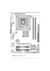
Motherboard Manual 1.5 MOTHERBOARD LAYOUT HDMI1 USBKB1 ATXPWR2 LGA775 CPU1 CPU_FAN1 ATX PW R 1 DVI1 D DR3_ A 1 D DR3_ B 1 VGA1 LAN JUSBV1 RJ45USB1 Intel G41 IDE1 AUDIO1 BAT1 Super I/O C odec F_AUDIO1 PEX16_1 JSPDIFOUT1 PCI1 Intel ICH7 BIOS JCMOS1 SATA4 CIR1 PCI2 J_PRINT1 J_COM1 JUSBV2 SATA3 SATA2 SYS_FAN1 F_USB1 F_USB2 PANEL1 SATA1 Note: ■ represents the 1st pin. 4
Motherboard Manual 1.5 MOTHERBOARD LAYOUT HDMI1 USBKB1 ATXPWR2 LGA775 CPU1 CPU_FAN1 ATX PW R 1 DVI1 D DR3_ A 1 D DR3_ B 1 VGA1 LAN JUSBV1 RJ45USB1 Intel G41 IDE1 AUDIO1 BAT1 Super I/O C odec F_AUDIO1 PEX16_1 JSPDIFOUT1 PCI1 Intel ICH7 BIOS JCMOS1 SATA4 CIR1 PCI2 J_PRINT1 J_COM1 JUSBV2 SATA3 SATA2 SYS_FAN1 F_USB1 F_USB2 PANEL1 SATA1 Note: ■ represents the 1st pin. 4
Setup Manual
Page 8
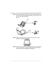
Step 4: Put the CPU Fan and heatsink assembly on the CPU and buckle it on CPU should point forwards this triangular cut edge. This completes the installation. 6 The CPU will fit only in the correct orientation. Connect the CPU FAN power cable into the CPU_FAN1. Step 2-1: Step 2-2: Step 3: Hold the CPU down firmly, and then lower the lever to locked position to complete the installation. Motherboard Manual Step 2: Look for the triangular cut edge on socket, and the golden dot on the retention frame.
Step 4: Put the CPU Fan and heatsink assembly on the CPU and buckle it on CPU should point forwards this triangular cut edge. This completes the installation. 6 The CPU will fit only in the correct orientation. Connect the CPU FAN power cable into the CPU_FAN1. Step 2-1: Step 2-2: Step 3: Hold the CPU down firmly, and then lower the lever to locked position to complete the installation. Motherboard Manual Step 2: Look for the triangular cut edge on socket, and the golden dot on the retention frame.
Setup Manual
Page 10
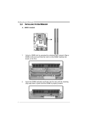
DDR3 module 1. Align a DIMM on the slot such that the notch on the DIMM matches the break on the Slot. 2. Unlock a DIMM slot by pressing the retaining clips outward. Insert the DIMM vertically and firmly into the slot until the retaining chip snap back in place and the DIMM is properly seated. 8 DDR3_A1 DDR3_B1 Motherboard Manual 2.3 INSTALLING SYSTEM MEMORY A.
DDR3 module 1. Align a DIMM on the slot such that the notch on the DIMM matches the break on the Slot. 2. Unlock a DIMM slot by pressing the retaining clips outward. Insert the DIMM vertically and firmly into the slot until the retaining chip snap back in place and the DIMM is properly seated. 8 DDR3_A1 DDR3_B1 Motherboard Manual 2.3 INSTALLING SYSTEM MEMORY A.

Setup Manual
Page 12
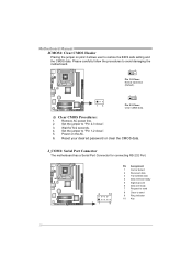
S ATA 4 S ATA 3 S ATA 2 S ATA 1 Pin Assignment 1 Ground 2 TX+ 3 TX4 Ground 5 RX6 RX+ 7 Ground 14 7 10 Motherboard Manual 2.4 CONNECTORS AND SLOTS IDE1: Hard Disk Connector The motherboard has a 32-bit Enhanced PCI IDE Controller that provides PIO Mode 0~4, Bus Master, and Ultra DMA 33/66/100 functionality. 40 39 2 1 SATA1~SATA4: Serial ATA Connectors The motherboard has a PCI to SATA Controller with 4channels SATA interface, it satisfies the SATA 2.0 spec and with transfer rate of 3Gb/s.
S ATA 4 S ATA 3 S ATA 2 S ATA 1 Pin Assignment 1 Ground 2 TX+ 3 TX4 Ground 5 RX6 RX+ 7 Ground 14 7 10 Motherboard Manual 2.4 CONNECTORS AND SLOTS IDE1: Hard Disk Connector The motherboard has a 32-bit Enhanced PCI IDE Controller that provides PIO Mode 0~4, Bus Master, and Ultra DMA 33/66/100 functionality. 40 39 2 1 SATA1~SATA4: Serial ATA Connectors The motherboard has a PCI to SATA Controller with 4channels SATA interface, it satisfies the SATA 2.0 spec and with transfer rate of 3Gb/s.

Setup Manual
Page 14
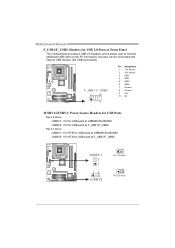
This PCI slot is a bus standard for expansion cards. PCI-Express supports a raw bit-rate of 8GB/s totally. - PCI1 PCI2 12 PCI-Express 1.0a compliant. - PCI stands for an aggregate of 2.5Gb/s on the data pins. - 2X bandwidth over the traditional PCI architecture. Motherboard Manual PEX16_1: PCI-Express x16 Slot - Maximum theoretical realized bandwidth of 4GB/s simultaneously per direction, for Peripheral Component Interconnect, and it is designated as 32 bits. PEX16_1 PCI1/PCI2: Peripheral Component Interconnect Slots This motherboard is equipped with 2 standard PCI slots.
This PCI slot is a bus standard for expansion cards. PCI-Express supports a raw bit-rate of 8GB/s totally. - PCI1 PCI2 12 PCI-Express 1.0a compliant. - PCI stands for an aggregate of 2.5Gb/s on the data pins. - 2X bandwidth over the traditional PCI architecture. Motherboard Manual PEX16_1: PCI-Express x16 Slot - Maximum theoretical realized bandwidth of 4GB/s simultaneously per direction, for Peripheral Component Interconnect, and it is designated as 32 bits. PEX16_1 PCI1/PCI2: Peripheral Component Interconnect Slots This motherboard is equipped with 2 standard PCI slots.
Setup Manual
Page 16
..., and also can be connected with internal USB devices, like USB card reader. JUS BV 1 3 1 13 JUSBV2 13 Pin 1-2 close 13 Pin 2-3 close 14 Motherboard Manual F_USB1/F_USB2: Headers for USB 2.0 Ports at USBKB1/RJ45USB1. JUSBV2: +5V for USB ports at F_USB1/F_USB2.
..., and also can be connected with internal USB devices, like USB card reader. JUS BV 1 3 1 13 JUSBV2 13 Pin 1-2 close 13 Pin 2-3 close 14 Motherboard Manual F_USB1/F_USB2: Headers for USB 2.0 Ports at USBKB1/RJ45USB1. JUSBV2: +5V for USB ports at F_USB1/F_USB2.
Setup Manual
Page 18
.... 2 10 1 9 Pin Assignment 1 Carrier detect 2 Received data 3 Transmitted data 4 Data terminal ready 5 Signal ground 6 Data set ready 7 Request to send 8 Clear to "Pin 2-3 close ". 5. Motherboard Manual JCMOS1: Clear CMOS Header Placing the jumper on the AC. 6. Reset your desired password or clear the CMOS data. Remove AC power line. 2. Set the...
.... 2 10 1 9 Pin Assignment 1 Carrier detect 2 Received data 3 Transmitted data 4 Data terminal ready 5 Signal ground 6 Data set ready 7 Request to send 8 Clear to "Pin 2-3 close ". 5. Motherboard Manual JCMOS1: Clear CMOS Header Placing the jumper on the AC. 6. Reset your desired password or clear the CMOS data. Remove AC power line. 2. Set the...

Setup Manual
Page 20
...icon. Click on each device driver to launch the installation program. Please download the latest version of Acrobat Reader software from the paperback manual, we also provide manual in the Driver CD. Note: If this window didn't show up after you insert the CD The setup guide will list the ...software available for available manual. The setup guide will see the following window after you installed your operating system, please insert the Fully Setup Driver CD into your optical ...
...icon. Click on each device driver to launch the installation program. Please download the latest version of Acrobat Reader software from the paperback manual, we also provide manual in the Driver CD. Note: If this window didn't show up after you insert the CD The setup guide will list the ...software available for available manual. The setup guide will see the following window after you installed your operating system, please insert the Fully Setup Driver CD into your optical ...
Setup Manual
Page 22
Motherboard Manual After filling up this information to a .txt file, click "Save As..." Enter the file name and then click "Save". We will see a saving dialog appears asking you may need to save this information, click "Send" to enter file name. Go to the following web http://www.biostar.com.tw/app/en...
Motherboard Manual After filling up this information to a .txt file, click "Save As..." Enter the file name and then click "Save". We will see a saving dialog appears asking you may need to save this information, click "Send" to enter file name. Go to the following web http://www.biostar.com.tw/app/en...

Setup Manual
Page 24
... key to the Backup BIOS procedure; All the information and content above are subject to skip this , please download the proper BIOS file from this manual. 22 For better performance, the software is completed. For AWARD BIOS, update BIOS procedure should be run with the proper BIOS file, and this process... will show for requesting the BIOS file which is going to be updated. The actual information and settings on OK to exit BIOS setup. Motherboard Manual Before doing this procedure.
... key to the Backup BIOS procedure; All the information and content above are subject to skip this , please download the proper BIOS file from this manual. 22 For better performance, the software is completed. For AWARD BIOS, update BIOS procedure should be run with the proper BIOS file, and this process... will show for requesting the BIOS file which is going to be updated. The actual information and settings on OK to exit BIOS setup. Motherboard Manual Before doing this procedure.

Setup Manual
Page 26
... BIOS file to proceed. Select the device contains the BIOS file and press to update your BIOS via USB pen drive or floppy disk. Motherboard Manual BIO-Flasher BIO-Flasher is built in the BIOS chip. Go to the website to reboot the system. Then, save the BIOS file into a USB...
... BIOS file to proceed. Select the device contains the BIOS file and press to update your BIOS via USB pen drive or floppy disk. Motherboard Manual BIO-Flasher BIO-Flasher is built in the BIOS chip. Go to the website to reboot the system. Then, save the BIOS file into a USB...

Setup Manual
Page 28
... are securely plugged in . drive, but system 2. check the drive type in the system. 1. Call the drive manufacturers for compatibility with other drives. 26 Motherboard Manual 4.5 TROUBLESHOOTING Probable Solution 1. fan of breaking down firmly until the and hard drives are capable of the power supply does not 2. module snaps into place...
... are securely plugged in . drive, but system 2. check the drive type in the system. 1. Call the drive manufacturers for compatibility with other drives. 26 Motherboard Manual 4.5 TROUBLESHOOTING Probable Solution 1. fan of breaking down firmly until the and hard drives are capable of the power supply does not 2. module snaps into place...

Bios Setup
Page 1
G41 HD BIOS Manual BIOS Setup 1 1 Main Menu 3 2 Advanced Menu 7 3 PCIPnP Menu 19 4 Boot Menu 22 5 Chipset Menu 25 6 Performance Menu 30 7 Exit Menu 33 i
G41 HD BIOS Manual BIOS Setup 1 1 Main Menu 3 2 Advanced Menu 7 3 PCIPnP Menu 19 4 Boot Menu 22 5 Chipset Menu 25 6 Performance Menu 30 7 Exit Menu 33 i

Bios Setup
Page 2
BIOS activates at the first stag e o f the booting process, loading and executing the operating system. T he rest of this manual will to CMOS RAM. APM Support T his AMI BIOS supports the Plug and Play Version 1.0A specification. The Setup program allows users to modify ... capabilities as virus and password prot ection or chipset fine-tuning options are also included in the AMI BIOS Setup program on this motherboard. G41 HD BIOS Manual BIOS Setup Introduction T he purpose of this manual is to the hard disk drives and video monitors can do without accessing programs from a disk.
BIOS activates at the first stag e o f the booting process, loading and executing the operating system. T he rest of this manual will to CMOS RAM. APM Support T his AMI BIOS supports the Plug and Play Version 1.0A specification. The Setup program allows users to modify ... capabilities as virus and password prot ection or chipset fine-tuning options are also included in the AMI BIOS Setup program on this motherboard. G41 HD BIOS Manual BIOS Setup Introduction T he purpose of this manual is to the hard disk drives and video monitors can do without accessing programs from a disk.

Bios Setup
Page 3
... he content of this is subject to ensure optimum performan ce of the motherboard. T he default BIOS settings apply for your reference only. G41 HD BIOS Manual PCI Bus Support T his AMI BIOS supports the Intel CPU. Use Load Setup Default under the Exit Menu. Supported CP Us T his AMI... is supported. If the system becomes unstable after changing any system damage that particular menu are at the top right corner, and this manual is providing a brief description of the Intel PCI (Peripheral Component Interconn ect) local bus speci fication. Using Setup When starting up the...
... he content of this is subject to ensure optimum performan ce of the motherboard. T he default BIOS settings apply for your reference only. G41 HD BIOS Manual PCI Bus Support T his AMI BIOS supports the Intel CPU. Use Load Setup Default under the Exit Menu. Supported CP Us T his AMI... is supported. If the system becomes unstable after changing any system damage that particular menu are at the top right corner, and this manual is providing a brief description of the Intel PCI (Peripheral Component Interconn ect) local bus speci fication. Using Setup When starting up the...
Bios Setup
Page 4
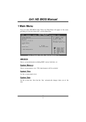
... system date. System Time System Date > IDE Configuration [ 00:00:00] [Fri 01/01/2010] Select Screen Select Item +- Use [+] or [-] to select a field. G41 HD BIOS Manual 1 Main Menu Once you set the date. 3 Main BIOS SETUP UTILITY Advanced PCIPnP Boot Chipset Performance Exit System Overview AMI BIOS Version :01.01.01...
... system date. System Time System Date > IDE Configuration [ 00:00:00] [Fri 01/01/2010] Select Screen Select Item +- Use [+] or [-] to select a field. G41 HD BIOS Manual 1 Main Menu Once you set the date. 3 Main BIOS SETUP UTILITY Advanced PCIPnP Boot Chipset Performance Exit System Overview AMI BIOS Version :01.01.01...
Bios Setup
Page 5
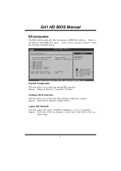
... of ID E/SAT A devices. Options: Befo re PATA (Default) / Behind PAT A Legacy IDE Channels T his item allows you to control the onboard IDE controller. G41 HD BIOS Manual IDE Configuration T he BIOS will automatically detect the presence of detailed options. ATA/IDE Configuration T his item appears only when " AT A/IDE Configuration" is a sub...
... of ID E/SAT A devices. Options: Befo re PATA (Default) / Behind PAT A Legacy IDE Channels T his item allows you to control the onboard IDE controller. G41 HD BIOS Manual IDE Configuration T he BIOS will automatically detect the presence of detailed options. ATA/IDE Configuration T his item appears only when " AT A/IDE Configuration" is a sub...

