
Setup Manual
Page 1
These limits are trademarks of their respective companies. Duplication of the FCC Rules. The vendor makes no guarantee that interference will not be responsible for any party beforehand. This equipment generates, uses and can radiate radio frequency energy and, if not installed and used in a particular installation. There is subject to be changed without notice and we will not occur in accordance with the instructions, may cause harmful interference to radio communications. The content of merchantability or fitness for any mistakes found to comply with respect to the ...
These limits are trademarks of their respective companies. Duplication of the FCC Rules. The vendor makes no guarantee that interference will not be responsible for any party beforehand. This equipment generates, uses and can radiate radio frequency energy and, if not installed and used in a particular installation. There is subject to be changed without notice and we will not occur in accordance with the instructions, may cause harmful interference to radio communications. The content of merchantability or fitness for any mistakes found to comply with respect to the ...

Setup Manual
Page 2
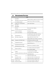
Table of Contents Chapter 1: Introduction 3 1.1 Before You Start 3 1.2 Package Checklist 3 1.3 Motherboard Features 4 1.4 Rear Panel Connectors 6 1.5 Motherboard Layout 7 Chapter 2: Hardware Installation 8 2.1 Installing Central Processing Unit (CPU 8 2.2 FAN Headers 10 2.3 Installing System Memory 11 2.4 Connectors and Slots 13 Chapter 3: Headers & Jumpers Setup 15 3.1 How to Setup Jumpers 15 3.2 Detail Settings 15 Chapter 4: RAID Functions 22 4.1 Operation System 22 4.2 Raid Arrays 22 4.3 How RAID Works 22 Chapter 5: OverClock Quick Guide ...
Table of Contents Chapter 1: Introduction 3 1.1 Before You Start 3 1.2 Package Checklist 3 1.3 Motherboard Features 4 1.4 Rear Panel Connectors 6 1.5 Motherboard Layout 7 Chapter 2: Hardware Installation 8 2.1 Installing Central Processing Unit (CPU 8 2.2 FAN Headers 10 2.3 Installing System Memory 11 2.4 Connectors and Slots 13 Chapter 3: Headers & Jumpers Setup 15 3.1 How to Setup Jumpers 15 3.2 Detail Settings 15 Chapter 4: RAID Functions 22 4.1 Operation System 22 4.2 Raid Arrays 22 4.3 How RAID Works 22 Chapter 5: OverClock Quick Guide ...
Setup Manual
Page 3
Hold the board on motherboard or the rear side of the board unless necessary. Loose parts will cause short circuits which may damage the equipment. „ Keep the computer from anti-static bag, ground yourself properly by touching any safely grounded appliance, or use grounded wrist strap to remove the static charge. „ Avoid touching the components on the edge, do not try to bend or flex the board. „ Do not leave any unfastened small parts inside the case after installation. CHAPTER 1: INTRODUCTION TA690G AM2 1.1 BEFORE YOU START Thank you take the motherboard out from ...
Hold the board on motherboard or the rear side of the board unless necessary. Loose parts will cause short circuits which may damage the equipment. „ Keep the computer from anti-static bag, ground yourself properly by touching any safely grounded appliance, or use grounded wrist strap to remove the static charge. „ Avoid touching the components on the edge, do not try to bend or flex the board. „ Do not leave any unfastened small parts inside the case after installation. CHAPTER 1: INTRODUCTION TA690G AM2 1.1 BEFORE YOU START Thank you take the motherboard out from ...
Setup Manual
Page 4
Motherboard Manual 1.3 MOTHERBOARD FEATURES SPEC Socket AM2 AMD 64 Architecture enables 32 and 64 bit computing CPU AMD Athlon 64 / Athlon 64 FX / Athlon 64 Supports Hyper Transport and Cool=n=Quiet x2 / Sempron processors FSB Supports up to 1 GHz Bandwidth Support HyperTransport Chipset AMD 690G AMD SB600 ITE 8716F Environment Control initiatives, Provides the most commonly used legacy H/W Monitor Super I/O Super I/O functionality. Fan Speed Controller Low Pin Count Interface ITE's "Smart Guardian" function Main Memory DDR2 DIMM Slots x 4 Max Memory Capacity 4GB ...
Motherboard Manual 1.3 MOTHERBOARD FEATURES SPEC Socket AM2 AMD 64 Architecture enables 32 and 64 bit computing CPU AMD Athlon 64 / Athlon 64 FX / Athlon 64 Supports Hyper Transport and Cool=n=Quiet x2 / Sempron processors FSB Supports up to 1 GHz Bandwidth Support HyperTransport Chipset AMD 690G AMD SB600 ITE 8716F Environment Control initiatives, Provides the most commonly used legacy H/W Monitor Super I/O Super I/O functionality. Fan Speed Controller Low Pin Count Interface ITE's "Smart Guardian" function Main Memory DDR2 DIMM Slots x 4 Max Memory Capacity 4GB ...

Setup Manual
Page 5
... monitor x1 Connect to RJ-45 ethernet cable x4 Connect to USB devices x6 Provide Audio-In/Out and microphone connection Micro ATX Size Board Biostar Reserves the right to add or remove support for any OS With or without notice. 5
... monitor x1 Connect to RJ-45 ethernet cable x4 Connect to USB devices x6 Provide Audio-In/Out and microphone connection Micro ATX Size Board Biostar Reserves the right to add or remove support for any OS With or without notice. 5

Setup Manual
Page 6
Motherboard Manual 1.4 REAR PANEL CONNECTORS X PS/2 Mouse Port Y PS/2 Keyboard Port Z S-Video TV-Out Port Transmit analog video signals to TV or any other display panels equipped with S-Video input. [ HDMI Port The High-Definition Multimedia Interface (HDMI) is an all-digital audio/video interface capable of transmitting uncompressed streams to an AV receiver or any other display panels equipped with D-Sub VGA input. ^ USB 2.0 Port x 4 _ 10/100/1000 Mbps LAN Port ` Audio Jack x 6 Port 2-Channel Blue Line-In Green Line-Out Pink Mic In Orange Black Rear Speaker Out Grey 4-...
Motherboard Manual 1.4 REAR PANEL CONNECTORS X PS/2 Mouse Port Y PS/2 Keyboard Port Z S-Video TV-Out Port Transmit analog video signals to TV or any other display panels equipped with S-Video input. [ HDMI Port The High-Definition Multimedia Interface (HDMI) is an all-digital audio/video interface capable of transmitting uncompressed streams to an AV receiver or any other display panels equipped with D-Sub VGA input. ^ USB 2.0 Port x 4 _ 10/100/1000 Mbps LAN Port ` Audio Jack x 6 Port 2-Channel Blue Line-In Green Line-Out Pink Mic In Orange Black Rear Speaker Out Grey 4-...

Setup Manual
Page 7
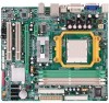
DVI-D VGA 1.5 MOTHERBOARD LAYOUT JKBMS1 JATXPWR2 JCFAN1 TA690G AM2 JATXPWR1 JTVOUT1 JHDMI DIMMA1 DIMMB1 DIMMA2 DIMMB2 Socket A M2 JUSB1 JUSBLAN1 JNFAN1 AMD 690G IDE1 FDD1 AUDIO1 LAN JAUDIOF1 PEX16_1 Codec PEX1_1 JSPDIF_OUT1 JSPDIF_IN1 JCDIN1 PCI1 BAT1 JCMOS1 AMD SB600 BIOS SATA2 SATA1 Super I/O JPRNT1 PCI2 JCOM1 JUSB2 JUSB3 LED_D1 LED_D2 SATA4 SATA3 JUSB4 JSFAN2 JPANEL1 PWRSW1 JSFAN1 RSTSW1 Note: ■ represents the 1st pin. 7
DVI-D VGA 1.5 MOTHERBOARD LAYOUT JKBMS1 JATXPWR2 JCFAN1 TA690G AM2 JATXPWR1 JTVOUT1 JHDMI DIMMA1 DIMMB1 DIMMA2 DIMMB2 Socket A M2 JUSB1 JUSBLAN1 JNFAN1 AMD 690G IDE1 FDD1 AUDIO1 LAN JAUDIOF1 PEX16_1 Codec PEX1_1 JSPDIF_OUT1 JSPDIF_IN1 JCDIN1 PCI1 BAT1 JCMOS1 AMD SB600 BIOS SATA2 SATA1 Super I/O JPRNT1 PCI2 JCOM1 JUSB2 JUSB3 LED_D1 LED_D2 SATA4 SATA3 JUSB4 JSFAN2 JPANEL1 PWRSW1 JSFAN1 RSTSW1 Note: ■ represents the 1st pin. 7

Setup Manual
Page 8
Step 2: Pull the lever toward direction A from the socket and then raise the lever up to a 90-degree angle. The CPU will fit only in the correct orientation. 8 Motherboard Manual CHAPTER 2: HARDWARE INSTALLATION 2.1 INSTALLING CENTRAL PROCESSING UNIT (CPU) Step 1: Remove the socket protection cap. Step 3: Look for the white triangle on socket, and the gold triangle on CPU should point towards this white triangle.
Step 2: Pull the lever toward direction A from the socket and then raise the lever up to a 90-degree angle. The CPU will fit only in the correct orientation. 8 Motherboard Manual CHAPTER 2: HARDWARE INSTALLATION 2.1 INSTALLING CENTRAL PROCESSING UNIT (CPU) Step 1: Remove the socket protection cap. Step 3: Look for the white triangle on socket, and the gold triangle on CPU should point towards this white triangle.
Setup Manual
Page 9
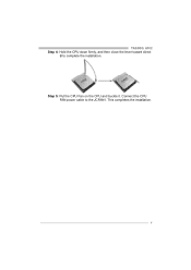
TA690G AM2 Step 4: Hold the CPU down firmly, and then close the lever toward direct B to the JCFAN1. Step 5: Put the CPU Fan on the CPU and buckle it. Connect the CPU FAN power cable to complete the installation. This completes the installation. 9
TA690G AM2 Step 4: Hold the CPU down firmly, and then close the lever toward direct B to the JCFAN1. Step 5: Put the CPU Fan on the CPU and buckle it. Connect the CPU FAN power cable to complete the installation. This completes the installation. 9

Setup Manual
Page 10
JCFAN1: CPU Fan Header 14 Pin Assignment 1 Ground 2 +12V 3 FAN RPM rate sense 4 Smart Fan Control (By Fan) JNFAN1: North Bridge Fan Header JSFAN1/JSFAN2: System Fan Header JNFAN1 3 1 JSFAN2/JSFAN1 13 Pin Assignment 1 Ground 2 +12V 3 FAN RPM rate sense Note: The JCFAN1 supports 4-pin head connector. The JSFAN1/JSFAN2 and JNFAN1 support 3-pin head connectors. When connecting with wires onto connectors, please note that the red wire is the positive and should be connected to pin#2, and the black wire is Ground and should be different according to GND. 10 The fan cable and connector...
JCFAN1: CPU Fan Header 14 Pin Assignment 1 Ground 2 +12V 3 FAN RPM rate sense 4 Smart Fan Control (By Fan) JNFAN1: North Bridge Fan Header JSFAN1/JSFAN2: System Fan Header JNFAN1 3 1 JSFAN2/JSFAN1 13 Pin Assignment 1 Ground 2 +12V 3 FAN RPM rate sense Note: The JCFAN1 supports 4-pin head connector. The JSFAN1/JSFAN2 and JNFAN1 support 3-pin head connectors. When connecting with wires onto connectors, please note that the red wire is the positive and should be connected to pin#2, and the black wire is Ground and should be different according to GND. 10 The fan cable and connector...
Setup Manual
Page 11
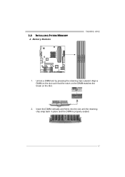
Insert the DIMM vertically and firmly into the slot until the retaining chip snap back in place and the DIMM is properly seated. 11 Align a DIMM on the slot such that the notch on the DIMM matches the break on the Slot. 2. Unlock a DIMM slot by pressing the retaining clips outward. 2.3 INSTALLING SYSTEM MEMORY A. Memory Modules TA690G AM2 DIMMA1 DIMMB1 DIMMA2 DIMMB2 1.
Insert the DIMM vertically and firmly into the slot until the retaining chip snap back in place and the DIMM is properly seated. 11 Align a DIMM on the slot such that the notch on the DIMM matches the break on the Slot. 2. Unlock a DIMM slot by pressing the retaining clips outward. 2.3 INSTALLING SYSTEM MEMORY A. Memory Modules TA690G AM2 DIMMA1 DIMMB1 DIMMA2 DIMMB2 1.

Setup Manual
Page 12
Dual Channel Memory installation To trigger the Dual Channel function of the same density in pairs, shown in the following requirements: Install memory module of the motherboard, the memory module must be the same (x8 or x16) 12 Dual Channel Status DIMMA1 DIMMB1 DIMMA2 DIMMB2 Enabled O O X X Enabled X X O O Enabled O O O O (O means memory installed, X means memory not installed.) The DRAM bus width of the memory module must meet the following table. Motherboard Manual B. Memory Capacity DIMM Socket Location DDR2 Module DIMMA1 256MB/512MB/1024MB DIMMB1 ...
Dual Channel Memory installation To trigger the Dual Channel function of the same density in pairs, shown in the following requirements: Install memory module of the motherboard, the memory module must be the same (x8 or x16) 12 Dual Channel Status DIMMA1 DIMMB1 DIMMA2 DIMMB2 Enabled O O X X Enabled X X O O Enabled O O O O (O means memory installed, X means memory not installed.) The DRAM bus width of the memory module must meet the following table. Motherboard Manual B. Memory Capacity DIMM Socket Location DDR2 Module DIMMA1 256MB/512MB/1024MB DIMMB1 ...
Setup Manual
Page 13
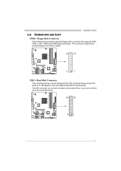
This connector supports the provided floppy drive ribbon cables. 34 33 2 1 IDE1: Hard Disk Connector The motherboard has a 32-bit Enhanced PCI IDE Controller that supports 360K, 720K, 1.2M, 1.44M and 2.88M floppy disk types. The IDE connector can connect a master and a slave drive, so you can connect up to two hard disk drives. 40 39 21 13 TA690G AM2 2.4 CONNECTORS AND SLOTS FDD1: Floppy Disk Connector The motherboard provides a standard floppy disk connector that provides PIO Mode 0~4, Bus Master, and Ultra DMA 33/66/100/133 functionality.
This connector supports the provided floppy drive ribbon cables. 34 33 2 1 IDE1: Hard Disk Connector The motherboard has a 32-bit Enhanced PCI IDE Controller that supports 360K, 720K, 1.2M, 1.44M and 2.88M floppy disk types. The IDE connector can connect a master and a slave drive, so you can connect up to two hard disk drives. 40 39 21 13 TA690G AM2 2.4 CONNECTORS AND SLOTS FDD1: Floppy Disk Connector The motherboard provides a standard floppy disk connector that provides PIO Mode 0~4, Bus Master, and Ultra DMA 33/66/100/133 functionality.

Setup Manual
Page 14
PCI1 PCI2 14 PCI-Express 1.0a compliant. - PCI-Express supports a raw bit-rate of 4GB/s simultaneously per direction; 500MB/s in total. - PCI stands for Peripheral Component Interconnect, and it is equipped with 2 standard PCI slots. Motherboard Manual PEX16_1: PCI-Express x16 Slot - PEX1_1: PCI-Express x1 slots - PEX16_1 PEX1_1 PCI1~PCI2: Peripheral Component Interconnect Slots This motherboard is a bus standard for an aggregate of 8GB/s totally. This PCI slot is designated as 32 bits. PCI-Express 1.0a compliant. - Data transfer bandwidth up to 250MB/s per direction, ...
PCI1 PCI2 14 PCI-Express 1.0a compliant. - PCI-Express supports a raw bit-rate of 4GB/s simultaneously per direction; 500MB/s in total. - PCI stands for Peripheral Component Interconnect, and it is equipped with 2 standard PCI slots. Motherboard Manual PEX16_1: PCI-Express x16 Slot - PEX1_1: PCI-Express x1 slots - PEX16_1 PEX1_1 PCI1~PCI2: Peripheral Component Interconnect Slots This motherboard is a bus standard for an aggregate of 8GB/s totally. This PCI slot is designated as 32 bits. PCI-Express 1.0a compliant. - Data transfer bandwidth up to 250MB/s per direction, ...
Setup Manual
Page 15
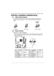
It allows user to set up jumpers. When the jumper cap is placed on , Reset, HDD LED, Power LED, Sleep button and speaker connection. TA690G AM2 CHAPTER 3: HEADERS & JUMPERS SETUP 3.1 HOW TO SETUP JUMPERS The illustration shows how to connect the PC case's front panel switch functions. Pin opened Pin closed Pin1-2 closed 3.2 DETAIL SETTINGS JPANEL1: Front Panel Header This 16-pin connector includes Power-on pins, the jumper is "close", if not, that means the jumper is "open". PWR_LED SLP On/Off ++ - 9 16 1 +- 8 SPK RST HLED Pin Assignment 1 +5V 2 N/A 3 N/A 4 ...
It allows user to set up jumpers. When the jumper cap is placed on , Reset, HDD LED, Power LED, Sleep button and speaker connection. TA690G AM2 CHAPTER 3: HEADERS & JUMPERS SETUP 3.1 HOW TO SETUP JUMPERS The illustration shows how to connect the PC case's front panel switch functions. Pin opened Pin closed Pin1-2 closed 3.2 DETAIL SETTINGS JPANEL1: Front Panel Header This 16-pin connector includes Power-on pins, the jumper is "close", if not, that means the jumper is "open". PWR_LED SLP On/Off ++ - 9 16 1 +- 8 SPK RST HLED Pin Assignment 1 +5V 2 N/A 3 N/A 4 ...

Setup Manual
Page 16
Motherboard Manual JATXPWR1: ATX Power Source Connector This connector allows user to connect 24-pin power connector on the ATX power supply. 12 24 Pin Assignment 13 +3.3V 14 -12V 15 Ground 16 PS_ON 17 Ground 18 Ground 19 Ground 20 NC 21 +5V 22 +5V 23 +5V 24 Ground 1 13 Pin Assignment 1 +3.3V 2 +3.3V 3 Ground 4 +5V 5 Ground 6 +5V 7 Ground 8 PW _OK 9 Standby Voltage+5V 10 +12V 11 +12V 12 +3.3V JATXPWR2: ATX Power Source Connector By connecting this connector, it will provide +12V to CPU power circuit. 1 4 2 3 Pin Assignment 1 +12V...
Motherboard Manual JATXPWR1: ATX Power Source Connector This connector allows user to connect 24-pin power connector on the ATX power supply. 12 24 Pin Assignment 13 +3.3V 14 -12V 15 Ground 16 PS_ON 17 Ground 18 Ground 19 Ground 20 NC 21 +5V 22 +5V 23 +5V 24 Ground 1 13 Pin Assignment 1 +3.3V 2 +3.3V 3 Ground 4 +5V 5 Ground 6 +5V 7 Ground 8 PW _OK 9 Standby Voltage+5V 10 +12V 11 +12V 12 +3.3V JATXPWR2: ATX Power Source Connector By connecting this connector, it will provide +12V to CPU power circuit. 1 4 2 3 Pin Assignment 1 +12V...
Setup Manual
Page 17
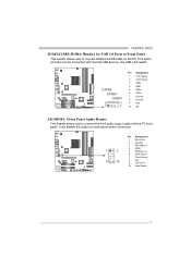
It will disable the output on the PC front panel, and also can be connected with the PC front panel. Pin Assignment 1 Mic Left in 2 Ground 3 Mic Right in 1 2 4 GPIO 5 Right line in 6 Jack Sense 7 Front Sense 9 10 8 Key 9 Left line in 10 Jack Sense 17 JUSB2 JUSB3 JUSB4 2 10 1 9 Pin Assignment 1 +5V (fused) 2 +5V (fused) 3 USB4 USB5 USB+ 6 USB+ 7 Ground 8 Ground 9 Key 10 NC JAUDIOF1: Front Panel Audio Header This header allows user to connect additional USB cable on back panel audio connectors. TA690G AM2 JUSB2/JUSB3/JUSB4: Headers for USB 2.0 Ports at Front Panel ...
It will disable the output on the PC front panel, and also can be connected with the PC front panel. Pin Assignment 1 Mic Left in 2 Ground 3 Mic Right in 1 2 4 GPIO 5 Right line in 6 Jack Sense 7 Front Sense 9 10 8 Key 9 Left line in 10 Jack Sense 17 JUSB2 JUSB3 JUSB4 2 10 1 9 Pin Assignment 1 +5V (fused) 2 +5V (fused) 3 USB4 USB5 USB+ 6 USB+ 7 Ground 8 Ground 9 Key 10 NC JAUDIOF1: Front Panel Audio Header This header allows user to connect additional USB cable on back panel audio connectors. TA690G AM2 JUSB2/JUSB3/JUSB4: Headers for USB 2.0 Ports at Front Panel ...

Setup Manual
Page 18
Remove AC power line. 2. Wait for five seconds. 4. Reset your desired password or clear the CMOS data. 18 Motherboard Manual JCDIN1: CD-ROM Audio-in Connector This connector allows user to connect the audio source from the variaty devices, like CD-ROM, DVD-ROM, PCI sound card, PCI TV turner card etc.. 4 1 Pin Assignment 1 Left Channel Input 2 Ground 3 Ground 4 Right Channel Input JCMOS1: Clear CMOS Header By placing the jumper on the AC. 6. Set the jumper to "Pin 1-2 close ". 3. Set the jumper to avoid damaging the motherboard. 13 13 Pin 1-2 Close: Normal Operation (default...
Remove AC power line. 2. Wait for five seconds. 4. Reset your desired password or clear the CMOS data. 18 Motherboard Manual JCDIN1: CD-ROM Audio-in Connector This connector allows user to connect the audio source from the variaty devices, like CD-ROM, DVD-ROM, PCI sound card, PCI TV turner card etc.. 4 1 Pin Assignment 1 Left Channel Input 2 Ground 3 Ground 4 Right Channel Input JCMOS1: Clear CMOS Header By placing the jumper on the AC. 6. Set the jumper to "Pin 1-2 close ". 3. Set the jumper to avoid damaging the motherboard. 13 13 Pin 1-2 Close: Normal Operation (default...
Setup Manual
Page 19
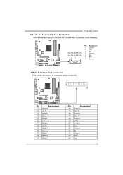
TA690G AM2 SATA1~SATA4: Serial ATA Connectors The motherboard has a PCI to connector printer on the PC. 2 1 25 Pin Assignment 1 -Strobe 2 -ALF 3 Data 0 4 -Error 5 Data 1 6 -Init 7 Data 2 8 -Scltin 9 Data 3 10 Ground 11 Data 4 12 Ground 13 Data 5 Pin Assignment 14 Ground 15 Data 6 16 Ground 17 Data 7 18 Ground 19 -ACK 20 Ground 21 Busy 22 Ground 23 PE 24 Ground 25 SCLT 26 Key 19 Pin Assignment 1 Ground 2 TX+ SATA2 SATA1 3 4 TXGround SATA4 SATA3 5 RX- 14 7 6 RX+ 7 Ground JPRNT1: Printer Port Connector This header allows you to SATA Controller with 4 ...
TA690G AM2 SATA1~SATA4: Serial ATA Connectors The motherboard has a PCI to connector printer on the PC. 2 1 25 Pin Assignment 1 -Strobe 2 -ALF 3 Data 0 4 -Error 5 Data 1 6 -Init 7 Data 2 8 -Scltin 9 Data 3 10 Ground 11 Data 4 12 Ground 13 Data 5 Pin Assignment 14 Ground 15 Data 6 16 Ground 17 Data 7 18 Ground 19 -ACK 20 Ground 21 Busy 22 Ground 23 PE 24 Ground 25 SCLT 26 Key 19 Pin Assignment 1 Ground 2 TX+ SATA2 SATA1 3 4 TXGround SATA4 SATA3 5 RX- 14 7 6 RX+ 7 Ground JPRNT1: Printer Port Connector This header allows you to SATA Controller with 4 ...

Setup Manual
Page 20
Motherboard Manual JSPDIF_OUT1: Digital Audio-out Connector This connector allows user to connect the PCI bracket SPDIF input header. Pin Assignment 1 +5V 2 SPDIF_OUT 3 Ground 3 1 JSPDIF_IN1: Digital Audio-out Connector (Optional) This connector allows user to connect the PCI bracket SPDIF output header. Pin Assignment 2 10 1 Carrier detect 2 Received data 3 Transmitted data 1 9 4 Data terminal ready 5 Signal ground 6 Data set ready 7 Request to send 8 Clear to send 9 Ring indicator 10 Key 20 Pin Assignment 1 +5V 2 SPDIF_IN 3 Ground 3 1 JCOM1: Serial port Connector The ...
Motherboard Manual JSPDIF_OUT1: Digital Audio-out Connector This connector allows user to connect the PCI bracket SPDIF input header. Pin Assignment 1 +5V 2 SPDIF_OUT 3 Ground 3 1 JSPDIF_IN1: Digital Audio-out Connector (Optional) This connector allows user to connect the PCI bracket SPDIF output header. Pin Assignment 2 10 1 Carrier detect 2 Received data 3 Transmitted data 1 9 4 Data terminal ready 5 Signal ground 6 Data set ready 7 Request to send 8 Clear to send 9 Ring indicator 10 Key 20 Pin Assignment 1 +5V 2 SPDIF_IN 3 Ground 3 1 JCOM1: Serial port Connector The ...