
Setup Manual
Page 5
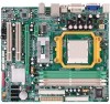
... header CMOS clear header USB connector Serial port Connector Power Connector (24pin) Power Connector (4pin) PS/2 Keyboard PS/2 Mouse S-Video port Back Panel I/O HDMI port VGA port DVI-D port LAN port USB Port Audio Jack Board Size 244 mm(W) x 244 mm(L) Special Features RAID 0 / 1 / 1+0 support OS Support Windows XP / VISTA TA690G... monitor x1 Connect to RJ-45 ethernet cable x4 Connect to USB devices x6 Provide Audio-In/Out and microphone connection Micro ATX Size Board Biostar Reserves the right to add or remove support for any OS With or without notice. 5
... header CMOS clear header USB connector Serial port Connector Power Connector (24pin) Power Connector (4pin) PS/2 Keyboard PS/2 Mouse S-Video port Back Panel I/O HDMI port VGA port DVI-D port LAN port USB Port Audio Jack Board Size 244 mm(W) x 244 mm(L) Special Features RAID 0 / 1 / 1+0 support OS Support Windows XP / VISTA TA690G... monitor x1 Connect to RJ-45 ethernet cable x4 Connect to USB devices x6 Provide Audio-In/Out and microphone connection Micro ATX Size Board Biostar Reserves the right to add or remove support for any OS With or without notice. 5

Setup Manual
Page 6
... Interface (HDMI) is a video interface transmitting digital video signals to digital display devices such as a digital television. \ DVI-D VGA Port The Digital Visual Interface (DVI) is an all-digital audio/video interface capable of transmitting uncompressed streams to different display panels ...flat panel LCDs or digital projectors. The DVI-D connector allows digital signals transmission only. ] D-Sub VGA Port Transmit analog video signals to computer monitor or any other display panels equipped with D-Sub VGA input. ^ USB 2.0 Port x 4 _ 10/100/1000 Mbps LAN Port ` Audio Jack...
... Interface (HDMI) is a video interface transmitting digital video signals to digital display devices such as a digital television. \ DVI-D VGA Port The Digital Visual Interface (DVI) is an all-digital audio/video interface capable of transmitting uncompressed streams to different display panels ...flat panel LCDs or digital projectors. The DVI-D connector allows digital signals transmission only. ] D-Sub VGA Port Transmit analog video signals to computer monitor or any other display panels equipped with D-Sub VGA input. ^ USB 2.0 Port x 4 _ 10/100/1000 Mbps LAN Port ` Audio Jack...

Setup Manual
Page 7
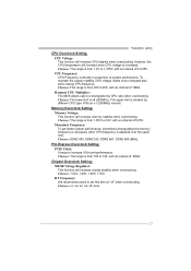
DVI-D VGA 1.5 MOTHERBOARD LAYOUT JKBMS1 JATXPWR2 JCFAN1 TA690G AM2 JATXPWR1 JTVOUT1 JHDMI DIMMA1 DIMMB1 DIMMA2 DIMMB2 Socket A M2 JUSB1 JUSBLAN1 JNFAN1 AMD 690G IDE1 FDD1 AUDIO1 LAN JAUDIOF1 PEX16_1 Codec PEX1_1 JSPDIF_OUT1 JSPDIF_IN1 JCDIN1 PCI1 BAT1 JCMOS1 AMD SB600 BIOS SATA2 SATA1 Super I/O JPRNT1 PCI2 JCOM1 JUSB2 JUSB3 LED_D1 LED_D2 SATA4 SATA3 JUSB4 JSFAN2 JPANEL1 PWRSW1 JSFAN1 RSTSW1 Note: ■ represents the 1st pin. 7
DVI-D VGA 1.5 MOTHERBOARD LAYOUT JKBMS1 JATXPWR2 JCFAN1 TA690G AM2 JATXPWR1 JTVOUT1 JHDMI DIMMA1 DIMMB1 DIMMA2 DIMMB2 Socket A M2 JUSB1 JUSBLAN1 JNFAN1 AMD 690G IDE1 FDD1 AUDIO1 LAN JAUDIOF1 PEX16_1 Codec PEX1_1 JSPDIF_OUT1 JSPDIF_IN1 JCDIN1 PCI1 BAT1 JCMOS1 AMD SB600 BIOS SATA2 SATA1 Super I/O JPRNT1 PCI2 JCOM1 JUSB2 JUSB3 LED_D1 LED_D2 SATA4 SATA3 JUSB4 JSFAN2 JPANEL1 PWRSW1 JSFAN1 RSTSW1 Note: ■ represents the 1st pin. 7
Setup Manual
Page 21
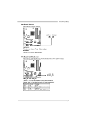
On-Board LED Indicators There are 2 on-board buttons. TA690G AM2 RSTSW1 PWRSW1 PWRSW1: This is an on-board Reset button. RSTSW1: This is an on-board Power Switch button. Please refer to show system status. LED_D1 LED_D2 LED_D1 and LED_D2: These 2 LED indicate system power on diagnostics. On-Board Buttons There are 2 LED indicators on the motherboard to the table below for different messages: LED_D1 ON ON OFF OFF LED_D2 ON OFF ON OFF Message Normal Memory Error VGA Error Abnormal: CPU / Chipset error. 21
On-Board LED Indicators There are 2 on-board buttons. TA690G AM2 RSTSW1 PWRSW1 PWRSW1: This is an on-board Reset button. RSTSW1: This is an on-board Power Switch button. Please refer to show system status. LED_D1 LED_D2 LED_D1 and LED_D2: These 2 LED indicate system power on diagnostics. On-Board Buttons There are 2 LED indicators on the motherboard to the table below for different messages: LED_D1 ON ON OFF OFF LED_D2 ON OFF ON OFF Message Normal Memory Error VGA Error Abnormal: CPU / Chipset error. 21
Setup Manual
Page 27
... increase CPU stability when overclocking. To maintain the system stability, CPU voltage needs to system performance. Hammer CPU Multiplier: The MOS allows users to increase VGA card performance. PCI-Express Overclock Setting: PCIE Clock: It helps to downgrade the CPU ratio when overclocking. Choices: The range is adjusted over the upper...
... increase CPU stability when overclocking. To maintain the system stability, CPU voltage needs to system performance. Hammer CPU Multiplier: The MOS allows users to increase VGA card performance. PCI-Express Overclock Setting: PCIE Clock: It helps to downgrade the CPU ratio when overclocking. Choices: The range is adjusted over the upper...

Setup Manual
Page 38
...: 1.8V~2.8V. AGP/PCI-Express Overclocking Setting: By adjusting can configure three items for Memory overclocking. Interval: 1. Interval: 0.0125V. And this function helps to increase VGA card performance. B. C. Range: 100MHz~150MHz. CPU Frequency Range: 200MHz~450MHz. A. Interval: 0.1V. Memory Overclocking Settings: By adjusting can configure two items for CPU overclocking. Memory...
...: 1.8V~2.8V. AGP/PCI-Express Overclocking Setting: By adjusting can configure three items for Memory overclocking. Interval: 1. Interval: 0.0125V. And this function helps to increase VGA card performance. B. C. Range: 100MHz~150MHz. CPU Frequency Range: 200MHz~450MHz. A. Interval: 0.1V. Memory Overclocking Settings: By adjusting can configure two items for CPU overclocking. Memory...

User Manual
Page 5
...PS/2 Mouse x1 DVI port x1 VGA port x1 LAN port x1 USB Port x4 Audio Jack x3 215 mm(W) x 244 mm(L) RAID 0 / 1 / 1+0 support Windows XP / VISTA Biostar Reserves the right to add or remove support for any OS With or without notice. 3 A690G-M2 Ver 6.x ALC662 5.1 channels audio out... (24pin) x1 Power Connector (4pin) x1 Printer Port Connector x1 Serial port Connector x1 PS/2 Keyboard x1 PS/2 Mouse x1 DVI port x1 Back Panel VGA port x1 I/O LAN port x1 USB Port x4 Audio Jack x6 Board Size 215 mm(W) x 244 mm(L) Special Features RAID 0 / 1 / 1+0 support...
...PS/2 Mouse x1 DVI port x1 VGA port x1 LAN port x1 USB Port x4 Audio Jack x3 215 mm(W) x 244 mm(L) RAID 0 / 1 / 1+0 support Windows XP / VISTA Biostar Reserves the right to add or remove support for any OS With or without notice. 3 A690G-M2 Ver 6.x ALC662 5.1 channels audio out... (24pin) x1 Power Connector (4pin) x1 Printer Port Connector x1 Serial port Connector x1 PS/2 Keyboard x1 PS/2 Mouse x1 DVI port x1 Back Panel VGA port x1 I/O LAN port x1 USB Port x4 Audio Jack x6 Board Size 215 mm(W) x 244 mm(L) Special Features RAID 0 / 1 / 1+0 support...

User Manual
Page 6
... The Digital Visual Interface (DVI) is a video interface transmitting digital video signals to computer monitor or any other display panels equipped with D-Sub VGA input. \ USB 2.0 Port x 4 ] RJ-45 LAN Port ^ Audio Jack x 6 (for Ver 5.x) / Audio Jack x 3 (for Ver 6.x) Port Blue Green Pink Orange Black Grey 2-Channel Line-...In Front Speaker Out Mic In Center/S ubwoo fer Rear Speaker Out Side Speaker Out 4 The DVI-D connector allows digital signals transmission only. [ D-Sub VGA Port Transmit analog video signals to digital display devices such as flat panel LCDs or digital projectors.
... The Digital Visual Interface (DVI) is a video interface transmitting digital video signals to computer monitor or any other display panels equipped with D-Sub VGA input. \ USB 2.0 Port x 4 ] RJ-45 LAN Port ^ Audio Jack x 6 (for Ver 5.x) / Audio Jack x 3 (for Ver 6.x) Port Blue Green Pink Orange Black Grey 2-Channel Line-...In Front Speaker Out Mic In Center/S ubwoo fer Rear Speaker Out Side Speaker Out 4 The DVI-D connector allows digital signals transmission only. [ D-Sub VGA Port Transmit analog video signals to digital display devices such as flat panel LCDs or digital projectors.

User Manual
Page 7
1.5 MOTHERBOARD LAYOUT JKBMS1 JCOM1 JATXP WR2 A690G-M2 Super I/O Socket A M2 DVI VGA DI MMA1 DI MMB1 DI MMA2 DI MMB2 FDD1 JUSB1 JCFAN1 IDE1 JATXPWR1 JUSBLAN1 AUDIO1 (for Ver 5.x) AUDIO2 (for Ver 6.x) LAN PEX1_1 AMD 690G PEX16_1 PCI1 AMD SB600 JSFAN1 JCMOS1 BIOS BAT1 SATA4 SATA1 Codec PCI2 JAUDIOF1 JCDIN1 JSPDIF_OUT1 JUSB2 JUSB3 JUSB4 SATA3 JPRNT1 SATA2 JPANEL1 Note: ■ represents the 1st pin. 5
1.5 MOTHERBOARD LAYOUT JKBMS1 JCOM1 JATXP WR2 A690G-M2 Super I/O Socket A M2 DVI VGA DI MMA1 DI MMB1 DI MMA2 DI MMB2 FDD1 JUSB1 JCFAN1 IDE1 JATXPWR1 JUSBLAN1 AUDIO1 (for Ver 5.x) AUDIO2 (for Ver 6.x) LAN PEX1_1 AMD 690G PEX16_1 PCI1 AMD SB600 JSFAN1 JCMOS1 BIOS BAT1 SATA4 SATA1 Codec PCI2 JAUDIOF1 JCDIN1 JSPDIF_OUT1 JUSB2 JUSB3 JUSB4 SATA3 JPRNT1 SATA2 JPANEL1 Note: ■ represents the 1st pin. 5

User Manual
Page 28
... in the About panel, you do not need to power up CPU core voltage and Memory voltage. In addition, the frequency status of CPU, memory, VGA and PCI along with just one . 6.2 SYSTEM REQUIREMENT OS Support: Windows 98 SE, Windows Me, Windows 2000, Windows XP, Windows Vista DirectX: DirectX 8.1 or above...
... in the About panel, you do not need to power up CPU core voltage and Memory voltage. In addition, the frequency status of CPU, memory, VGA and PCI along with just one . 6.2 SYSTEM REQUIREMENT OS Support: Windows 98 SE, Windows Me, Windows 2000, Windows XP, Windows Vista DirectX: DirectX 8.1 or above...

User Manual
Page 30
Display the CPU Speed, CPU external clock, Memory clock, VGA clock, and PCI clock information. Main Panel If you double-click the desktop icon, [WarpSpeeder™ III] will appear on the desktop, just like the ...
Display the CPU Speed, CPU external clock, Memory clock, VGA clock, and PCI clock information. Main Panel If you double-click the desktop icon, [WarpSpeeder™ III] will appear on the desktop, just like the ...

