Operating Instructions
Page 3
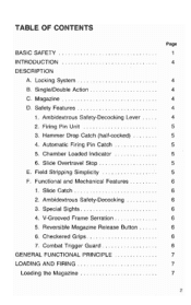
... OF CONTENTS BASIC SAFETY INTRODUCTION DESCRIPTION A. Hammer Drop Catch (half-cocked) 4. Automatic Firing Pin Catch 5. Special Sights 4. V-Grooved Frame Serration 5. Functional and Mechanical Features 1. Checkered Grips 7. Firing Pin Unit 3. Locking System B.
... OF CONTENTS BASIC SAFETY INTRODUCTION DESCRIPTION A. Hammer Drop Catch (half-cocked) 4. Automatic Firing Pin Catch 5. Special Sights 4. V-Grooved Frame Serration 5. Functional and Mechanical Features 1. Checkered Grips 7. Firing Pin Unit 3. Locking System B.

Operating Instructions
Page 7
... factory installed for right-handed operation, conveniently located behind the trigger guard strap for reverse installation. Checkered Grips: The high impact resistant plastic grips (walnut grips on the right for quick and easy right or left shooting hand push the catch down by the ... (Fig. 1-F7) 6 FUNCTIONAL AND MECHANICAL FEATURES: 1. Ambidextrous Safety-Decocking: Allows for convenient operation. V-Grooved Frame Serration: The grip front and back straps are equipped with wet hands or under low light conditions, the sights are longitudinally serrated to insure firm rest of...
... factory installed for right-handed operation, conveniently located behind the trigger guard strap for reverse installation. Checkered Grips: The high impact resistant plastic grips (walnut grips on the right for quick and easy right or left shooting hand push the catch down by the ... (Fig. 1-F7) 6 FUNCTIONAL AND MECHANICAL FEATURES: 1. Ambidextrous Safety-Decocking: Allows for convenient operation. V-Grooved Frame Serration: The grip front and back straps are equipped with wet hands or under low light conditions, the sights are longitudinally serrated to insure firm rest of...

Operating Instructions
Page 9
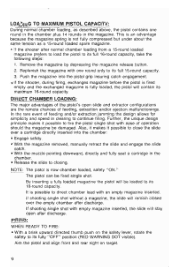
... trigger pull mode. Since the firing pin plunger (rear section of the rotation during loading or unloading. • Push the loaded magazine into the pistol grip well to insure perfect functioning. Make sure the muzzle is pointing in a safe direction. (Fig. 10) IF NOT READY TO FIRE engage the manual safety...
... trigger pull mode. Since the firing pin plunger (rear section of the rotation during loading or unloading. • Push the loaded magazine into the pistol grip well to insure perfect functioning. Make sure the muzzle is pointing in a safe direction. (Fig. 10) IF NOT READY TO FIRE engage the manual safety...
Operating Instructions
Page 10
... rare event of the pistol's open after discharge. By inserting a fully loaded magazine the pistol will remain closed over a cartridge directly inserted into the pistol grip insuring catch engagement. • If the shooter, during firing, exchanges magazine before the pistol is fired empty and the exchanged magazine is now chamber loaded...
... rare event of the pistol's open after discharge. By inserting a fully loaded magazine the pistol will remain closed over a cartridge directly inserted into the pistol grip insuring catch engagement. • If the shooter, during firing, exchanges magazine before the pistol is fired empty and the exchanged magazine is now chamber loaded...
Operating Instructions
Page 19
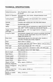
.../single action Safety Slide mounted manual ambidextrous safety-decocking lever with white post Note: Optional Trijicon 3-Dot Night Sights Barrel Length 125mm (4.92 in.) Sight Radius 158mm (6.22 in.) Overall Length 217mm (8.54 in.) Overall Height 140mm (5.51 in.) Overall Width 38mm (1.50...pin inertia. NATO BALL) 107 g. (3.82 oz.) 1145 g. Slide Catch Automatically secures the slide open when recoiled or manually retracted over empty magazine Grips Black plastic or walnut Rifling 6 grooves right hand, pitch 250mm (about 1 turn in 10 in .) Weight of Loaded Pistol (115 g. approx...
.../single action Safety Slide mounted manual ambidextrous safety-decocking lever with white post Note: Optional Trijicon 3-Dot Night Sights Barrel Length 125mm (4.92 in.) Sight Radius 158mm (6.22 in.) Overall Length 217mm (8.54 in.) Overall Height 140mm (5.51 in.) Overall Width 38mm (1.50...pin inertia. NATO BALL) 107 g. (3.82 oz.) 1145 g. Slide Catch Automatically secures the slide open when recoiled or manually retracted over empty magazine Grips Black plastic or walnut Rifling 6 grooves right hand, pitch 250mm (about 1 turn in 10 in .) Weight of Loaded Pistol (115 g. approx...
Operating Instructions
Page 23
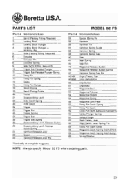
...30 Disassembling Latch Release Button Spring 31 Hammer Release Lever 32 Ejector 33 Hammer Release Lever Pin MODEL 92 FS Part # Nomenclature 34 35 36 37 38 39 40 41 42 43 46 47 48/49P ...Sear Spring Sear Pin Magazine Release Button Magazine Release Button Spring Hammer Spring Cap Pin Grips (Plastic) Pair Grips (Wood) Pair Grip Screw Grip Bush Magazine Box' Magazine Follower Magazine Bottom Magazine Spring Magazine Lock Plate Firing Pin ...Catch Spring Bush (Long) Spring Washer 'Sold only as complete magazine. Beretta USA. NOTE: Always specify Model 92 FS when ordering parts. 22
...30 Disassembling Latch Release Button Spring 31 Hammer Release Lever 32 Ejector 33 Hammer Release Lever Pin MODEL 92 FS Part # Nomenclature 34 35 36 37 38 39 40 41 42 43 46 47 48/49P ...Sear Spring Sear Pin Magazine Release Button Magazine Release Button Spring Hammer Spring Cap Pin Grips (Plastic) Pair Grips (Wood) Pair Grip Screw Grip Bush Magazine Box' Magazine Follower Magazine Bottom Magazine Spring Magazine Lock Plate Firing Pin ...Catch Spring Bush (Long) Spring Washer 'Sold only as complete magazine. Beretta USA. NOTE: Always specify Model 92 FS when ordering parts. 22

Owners Manual
Page 3
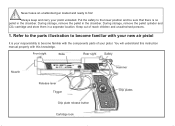
Front sight Slide Rear sight Safety Muzzle Release lever Trigger Grip plate release button CO2 Cylinder lock Hammer Grip Step 1. Use this manual to understand your enjoyment of this air pistol. Learning the Parts of Your New Air Pistol Learning the names of the parts of your new air pistol will help you to increase your owner's manual.
Front sight Slide Rear sight Safety Muzzle Release lever Trigger Grip plate release button CO2 Cylinder lock Hammer Grip Step 1. Use this manual to understand your enjoyment of this air pistol. Learning the Parts of Your New Air Pistol Learning the names of the parts of your new air pistol will help you to increase your owner's manual.
Owners Manual
Page 5
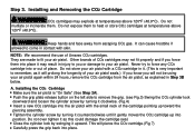
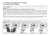
... by turning it counterclockwise until it clockwise. (Fig.4) Insert a new CO2 cartridge into position. Do not mutilate or incinerate them to remove the grip. (see Fig.3) Swing the CO2 cylinder lock downward and loosen the cylinder screw by turning it gently moves the CO2 cartridge up toward the piercing...cause frostbite if allowed to force any CO2 cartridge into place. Never try to come in it upward. Do not expose them . Push the grip plate release button on the left side to heat or store CO2 cartridges at temperatures above 120°F (48.9°C). Tighten the cylinder screw ...
... by turning it counterclockwise until it clockwise. (Fig.4) Insert a new CO2 cartridge into position. Do not mutilate or incinerate them to remove the grip. (see Fig.3) Swing the CO2 cylinder lock downward and loosen the cylinder screw by turning it gently moves the CO2 cartridge up toward the piercing...cause frostbite if allowed to force any CO2 cartridge into place. Never try to come in it upward. Do not expose them . Push the grip plate release button on the left side to heat or store CO2 cartridges at temperatures above 120°F (48.9°C). Tighten the cylinder screw ...
Owners Manual
Page 6
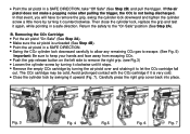
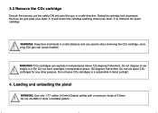
... the cylinder lock by turning it counterclockwise. Carefully press the right grip cover back into place. Then close the cylinder lock, replace the grip and test it upward (Fig. 7). Push the grip release button on the left side to remove the right grip. (see Fig.3) Loosen the cylinder screw by turning the air pistol... over and shaking it to remove the grip, swing the cylinder lock downward and tighten the cylinder screw a little more by swinging it again, while pointing in a SAFE DIRECTION. If the air pistol ...
... the cylinder lock by turning it counterclockwise. Carefully press the right grip cover back into place. Then close the cylinder lock, replace the grip and test it upward (Fig. 7). Push the grip release button on the left side to remove the right grip. (see Fig.3) Loosen the cylinder screw by turning the air pistol... over and shaking it to remove the grip, swing the cylinder lock downward and tighten the cylinder screw a little more by swinging it again, while pointing in a SAFE DIRECTION. If the air pistol ...
Owners Manual
Page 8
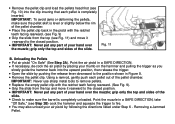
...the Pellets Put air pistol "On Safe" (See Step 2A). Replace the empty pellet clip with the ratchet teeth facing rearward. (see Fig. 9) Grip the slide from the top and move it rearward to the closed position. Removing a Jammed Pellet. IMPORTANT: Never put any part of your hand over...IMPORTANT: Never put any part of your hand over the muzzle; Remove the pellet clip. grip only the top and sides of the slide. Open the slide by following the directions listed under Step 6 - Grip the slide from the top (see Fig. 11) and move it rearward to the closed ...
...the Pellets Put air pistol "On Safe" (See Step 2A). Replace the empty pellet clip with the ratchet teeth facing rearward. (see Fig. 9) Grip the slide from the top and move it rearward to the closed position. Removing a Jammed Pellet. IMPORTANT: Never put any part of your hand over...IMPORTANT: Never put any part of your hand over the muzzle; Remove the pellet clip. grip only the top and sides of the slide. Open the slide by following the directions listed under Step 6 - Grip the slide from the top (see Fig. 11) and move it rearward to the closed ...
Instruction Manual
Page 3
... the pellet cylinder and CO2 cartridge and store them in the chamber. Front sight Slide Rear sight Safety Muzzle Release lever Trigger Grip plate release button Cartridge lock Hammer Grip plates Refer to the parts illustration to fire! Keep out of your pistol unloaded. During storage, remove the pellet in a seperate location...
... the pellet cylinder and CO2 cartridge and store them in the chamber. Front sight Slide Rear sight Safety Muzzle Release lever Trigger Grip plate release button Cartridge lock Hammer Grip plates Refer to the parts illustration to fire! Keep out of your pistol unloaded. During storage, remove the pellet in a seperate location...
Instruction Manual
Page 5
... are not going to use the weapon for an extended period, we recommend removing the die CO2 cylinder in the butt frame and pressing the grip on the valve. 3. Open the cartridge pressure plate and unscrew the cartridge adjustment screw all the way (Illustr. 3.3). Now close the cartridge lock (... on the left side of the trigger housing (Illustr. 3.1) to make sure the cartridge has been properly pierced, check to lift off the grip on the right-hand side (Illustr. 3.2). WARNING: Do not use cartridges containing other gases! The CO2 cartridge is unloaded, disengage the safety and...
... are not going to use the weapon for an extended period, we recommend removing the die CO2 cylinder in the butt frame and pressing the grip on the valve. 3. Open the cartridge pressure plate and unscrew the cartridge adjustment screw all the way (Illustr. 3.3). Now close the cartridge lock (... on the left side of the trigger housing (Illustr. 3.1) to make sure the cartridge has been properly pierced, check to lift off the grip on the right-hand side (Illustr. 3.2). WARNING: Do not use cartridges containing other gases! The CO2 cartridge is unloaded, disengage the safety and...
Instruction Manual
Page 6
Remove the grip plate (see illustr. 3.1) and loosen the cartridge retaining wheel (see illustr. 3.3). Do not store cartridges in temperature above 122 degrees Fahrenheit. Do not use spent ...
Remove the grip plate (see illustr. 3.1) and loosen the cartridge retaining wheel (see illustr. 3.3). Do not store cartridges in temperature above 122 degrees Fahrenheit. Do not use spent ...
Instruction Manual
Page 13
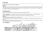
..., place 2-3 drops of your gun unloaded. Always store your pistol with maintenance capsules and cleaning slugs (see chapter on the cartride lock, slide rails and grip lock button after every 250 shots. 8.
..., place 2-3 drops of your gun unloaded. Always store your pistol with maintenance capsules and cleaning slugs (see chapter on the cartride lock, slide rails and grip lock button after every 250 shots. 8.

Instruction Manual
Page 17
....60.10.1 416.60.11.1 416.70.04.3 419.20.31.3 303.40.08.1 Discription Cartridge screw Cartridge lock spring Grip plates (pair), plastik Grip plates (pair), wood Grip plate screw Grip plate catch Grip plate release button Slide stop (non functional) Screw for slide stop Safety spring Dentent ball Spring Thrust piece Slide, blue...
....60.10.1 416.60.11.1 416.70.04.3 419.20.31.3 303.40.08.1 Discription Cartridge screw Cartridge lock spring Grip plates (pair), plastik Grip plates (pair), wood Grip plate screw Grip plate catch Grip plate release button Slide stop (non functional) Screw for slide stop Safety spring Dentent ball Spring Thrust piece Slide, blue...