Manual
Page 9
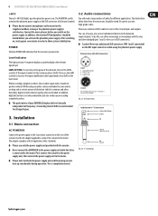
... recorder's peak meter should be bridged Fig. 3.1: XLR connections Unbalanced ¼" TS connector strain relief clamp sleeve tip 3.1 Mains connection AC POWER IN Connect the power supply to allow system stabilization. The illustrations below show 0 dB on . In addition, the monitor/PA ... on the XLR connectors of distortion (which is powered on . Fig. 3.2: 1/4" mono plug sleeve (ground/shield) tip (signal) 9 EURORACK UB1202/UB1002/UB802/UB502 User Manual +48 V The red +48 V LED lights up considerably during operation. one minute in the case of frequency. Then ...
... recorder's peak meter should be bridged Fig. 3.1: XLR connections Unbalanced ¼" TS connector strain relief clamp sleeve tip 3.1 Mains connection AC POWER IN Connect the power supply to allow system stabilization. The illustrations below show 0 dB on . In addition, the monitor/PA ... on the XLR connectors of distortion (which is powered on . Fig. 3.2: 1/4" mono plug sleeve (ground/shield) tip (signal) 9 EURORACK UB1202/UB1002/UB802/UB502 User Manual +48 V The red +48 V LED lights up considerably during operation. one minute in the case of frequency. Then ...

