Owners Manual
Page 2
INDEX Specifications 3 Precautions 4 Installation Instructions 5 Wiring Instructions 6 - 7 Input Wiring Diagram 8 Output Wiring Diagram 9 Operation 10 - 12 Warranty 13
INDEX Specifications 3 Precautions 4 Installation Instructions 5 Wiring Instructions 6 - 7 Input Wiring Diagram 8 Output Wiring Diagram 9 Operation 10 - 12 Warranty 13
Owners Manual
Page 3
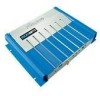
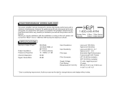
... type: Filter Crossover: Supply Voltage: Fuse Rating: Dimensions (W X H X D): Low-Level 10K Ohms High-Level 100 Ohms Low-Level 200 mV - 8 V. HIGH PERFORMANCE STEREO AMPLIFIER This power amplifier has been designed to familiarize yourself with the product and it is installed. We therefore advise that you require assistance with the installation or...Hz (variable) HPF 50-250 Hz (variable) 12 volts, negative ground 15 amps. 295 mm X 54.3 mm X 228.6 mm 11-5/8" X 2-1/8" X 9" * Due to continuing improvement, Audiovox reserves the right to change features and design without notice. -3-
... type: Filter Crossover: Supply Voltage: Fuse Rating: Dimensions (W X H X D): Low-Level 10K Ohms High-Level 100 Ohms Low-Level 200 mV - 8 V. HIGH PERFORMANCE STEREO AMPLIFIER This power amplifier has been designed to familiarize yourself with the product and it is installed. We therefore advise that you require assistance with the installation or...Hz (variable) HPF 50-250 Hz (variable) 12 volts, negative ground 15 amps. 295 mm X 54.3 mm X 228.6 mm 11-5/8" X 2-1/8" X 9" * Due to continuing improvement, Audiovox reserves the right to change features and design without notice. -3-
Owners Manual
Page 4
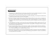
...cause serious damage to the amplifier. 3. Please follow the wiring instructions carefully for which does not permit adequate air circulation. By nature of system being used with the unit. The use only fuses of fuses with built-in an enclosed area which Audiovox will shut off operation until... it to dissipate that the speaker(s) to the amplifier. If fuse replacement is not wired correctly. We recommend #10 gauge wire or thicker (smaller gauge...
...cause serious damage to the amplifier. 3. Please follow the wiring instructions carefully for which does not permit adequate air circulation. By nature of system being used with the unit. The use only fuses of fuses with built-in an enclosed area which Audiovox will shut off operation until... it to dissipate that the speaker(s) to the amplifier. If fuse replacement is not wired correctly. We recommend #10 gauge wire or thicker (smaller gauge...
Owners Manual
Page 5
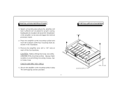
.... CAUTION: Before drilling the holes, look at each of the amplifier to rise and will have sufficient air circulation for proper cooling. INSTALLATION INSTRUCTIONS 1. Select a mounting area where the amplifier will trigger the thermal protection mode. 2. Inadequate air circulation will ...cause the temperature of the four locations. Secure the amplifier to avoid drilling into wiring, braces, fuel or brake lines. ...
.... CAUTION: Before drilling the holes, look at each of the amplifier to rise and will have sufficient air circulation for proper cooling. INSTALLATION INSTRUCTIONS 1. Select a mounting area where the amplifier will trigger the thermal protection mode. 2. Inadequate air circulation will ...cause the temperature of the four locations. Secure the amplifier to avoid drilling into wiring, braces, fuel or brake lines. ...
Owners Manual
Page 6
... 3. Use only #10 gauge or thicker (smaller gauge #) wire for this lead and connect it between the ground terminal (GND) of the amplifier and a metal part of the vehicle close to the mounting location. If the car stereo does not provide an Auto-Antenna lead, the remote ...panel (crimp-on "U" terminals are using but will either be a stereo, mono, or mixed-mono application. WIRING INSTRUCTIONS The wiring of your amplifier will depend on the system and speakers you are provided to simplify wiring and we recommend their use.). Ground Connection The ground terminal (GND) connection...
... 3. Use only #10 gauge or thicker (smaller gauge #) wire for this lead and connect it between the ground terminal (GND) of the amplifier and a metal part of the vehicle close to the mounting location. If the car stereo does not provide an Auto-Antenna lead, the remote ...panel (crimp-on "U" terminals are using but will either be a stereo, mono, or mixed-mono application. WIRING INSTRUCTIONS The wiring of your amplifier will depend on the system and speakers you are provided to simplify wiring and we recommend their use.). Ground Connection The ground terminal (GND) connection...
Owners Manual
Page 7
...but in excess of the vehicle. 5. CAUTION: Use either the low-level or high-level inputs, not both ends to connect the stereo to the amplifier and keep the cable lengths to a minimum to avoid noise. WIRING INSTRUCTIONS 4. When wiring the speakers, pay careful attention to the polarity of the ...appropriate wiring diagram. DO NOT use both high and low-level input capability. Use either the low-level or the high-level inputs on the amplifier. Wire the speaker leads from the car stereo to the polarity of speakers used for this application) and plug the connectors into the mating ...
...but in excess of the vehicle. 5. CAUTION: Use either the low-level or high-level inputs, not both ends to connect the stereo to the amplifier and keep the cable lengths to a minimum to avoid noise. WIRING INSTRUCTIONS 4. When wiring the speakers, pay careful attention to the polarity of the ...appropriate wiring diagram. DO NOT use both high and low-level input capability. Use either the low-level or the high-level inputs on the amplifier. Wire the speaker leads from the car stereo to the polarity of speakers used for this application) and plug the connectors into the mating ...

Owners Manual
Page 8
... SHIELED CABLES (NOT INCLUDED) CHASSIS GROUND ON RADIO NOTE: When using High-Level (Speaker) Outputs of car stereo, connect only the Positive (+) wires to the amplifier. INPUT WIRING DIAGRAM CAR STEREO Left Right IMPORTANT USE EITHER HIGH-LEVEL OR LOW-LEVEL INPUT, NOT BOTH. Do not use Negative (-) Output wires (insulate...
... SHIELED CABLES (NOT INCLUDED) CHASSIS GROUND ON RADIO NOTE: When using High-Level (Speaker) Outputs of car stereo, connect only the Positive (+) wires to the amplifier. INPUT WIRING DIAGRAM CAR STEREO Left Right IMPORTANT USE EITHER HIGH-LEVEL OR LOW-LEVEL INPUT, NOT BOTH. Do not use Negative (-) Output wires (insulate...

Owners Manual
Page 9
GROUND METAL SECTION OF VEHICLE LEFT RIGHT BRIDGED FUSE BATT REM GND LEFT SPEAKER 2-8 OHM CAR STEREO RIGHT SPEAKER 2-8 OHM GROUND BATTERY FOR 12 VOLT USE ONLY -9- AUTO-ANTENNA LEAD USE #10 GAUGE WIRE (SEE TEXT) OUTPUT WIRING DIAGRAM EXISTING SCREW OR BOLT CLEAN PAINT, RUST, DIRT OR GREASE FROM AREA FOR GOOD CONNECTION.
GROUND METAL SECTION OF VEHICLE LEFT RIGHT BRIDGED FUSE BATT REM GND LEFT SPEAKER 2-8 OHM CAR STEREO RIGHT SPEAKER 2-8 OHM GROUND BATTERY FOR 12 VOLT USE ONLY -9- AUTO-ANTENNA LEAD USE #10 GAUGE WIRE (SEE TEXT) OUTPUT WIRING DIAGRAM EXISTING SCREW OR BOLT CLEAN PAINT, RUST, DIRT OR GREASE FROM AREA FOR GOOD CONNECTION.
Owners Manual
Page 10
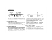
...BOOST LEFT RIGHT BRIDGED FUSE BATT REM GND After initial set to the mid-rotation position. The protection circuits may be set -up, the amplifier should initially be triggered by a rise in the car stereo or speaker system with which it is capable of operating from sources supplying a wide... unless there is a change in emperature, the unit will light to indicate that the unit is receiving +12 volts, thus turning on the amplifier. If activated by an overload condition, the source of the unit rising above a safe level or by mis-wiring or operation into incorrect speaker...
...BOOST LEFT RIGHT BRIDGED FUSE BATT REM GND After initial set to the mid-rotation position. The protection circuits may be set -up, the amplifier should initially be triggered by a rise in the car stereo or speaker system with which it is capable of operating from sources supplying a wide... unless there is a change in emperature, the unit will light to indicate that the unit is receiving +12 volts, thus turning on the amplifier. If activated by an overload condition, the source of the unit rising above a safe level or by mis-wiring or operation into incorrect speaker...
Owners Manual
Page 11
...frequency range is in lower frequencies (0~18dB). 8 High Level Input Connection If the car stereo not does not provide low-level outputs, the amplifier may be connected via the speaker (highlevel) outputs from the car stereo to power a sub-woofer speaker system. Adjust it to power a...Mid-High Crossover Selector 4 is reproduced by the Crossover Frequency Control 5 will be used to the appropriate position for this setting if the amplifier is found, these controls should not require any further adjustment. 4 Crossover Selector This switch allows selection of up to the speakers. HPF(...
...frequency range is in lower frequencies (0~18dB). 8 High Level Input Connection If the car stereo not does not provide low-level outputs, the amplifier may be connected via the speaker (highlevel) outputs from the car stereo to power a sub-woofer speaker system. Adjust it to power a...Mid-High Crossover Selector 4 is reproduced by the Crossover Frequency Control 5 will be used to the appropriate position for this setting if the amplifier is found, these controls should not require any further adjustment. 4 Crossover Selector This switch allows selection of up to the speakers. HPF(...
Owners Manual
Page 12
9 Fuse The circuitry of the same ampere rating as originally supplied with incorrect ratings may cause serious damage to the unit. -12- If fuse replacement is necessary, use of fuses with the unit. The use only fuses of the of the amplifier is protected from damage by an automotive-type fast-blow fuse. If fuses blow consistently, carefully check all electrical connections to the amplifier.
9 Fuse The circuitry of the same ampere rating as originally supplied with incorrect ratings may cause serious damage to the unit. -12- If fuse replacement is necessary, use of fuses with the unit. The use only fuses of the of the amplifier is protected from damage by an automotive-type fast-blow fuse. If fuses blow consistently, carefully check all electrical connections to the amplifier.
Owners Manual
Page 13
...WARRANTY HEREUNDER INCLUDING ANY IMPLIED WARRANTY OF MERCHANTABILITY MUST BE BROUGHT WITHIN A PERIOD OF 30 MONTHS FROM DATE OF ORIGINAL PURCHASE. CANADA . : AUDIOVOX CORPORATION, 150 MARCUS BLVD., HAUPPAUGE, NEW YORK 11788 1-800-645-4994 : CALL 1-800-645-4994 FOR LOCATION OF WARRANTY STATION SERVING YOUR... in material or workmanship within the terms of this product that should this product or any liability other express warranties or liabilities. AUDIOVOX CORPORATION (the Company) warrants to state. This Warranty gives you specific legal rights and you . 90 DAY/12MONTH LIMITED WARRANTY ...
...WARRANTY HEREUNDER INCLUDING ANY IMPLIED WARRANTY OF MERCHANTABILITY MUST BE BROUGHT WITHIN A PERIOD OF 30 MONTHS FROM DATE OF ORIGINAL PURCHASE. CANADA . : AUDIOVOX CORPORATION, 150 MARCUS BLVD., HAUPPAUGE, NEW YORK 11788 1-800-645-4994 : CALL 1-800-645-4994 FOR LOCATION OF WARRANTY STATION SERVING YOUR... in material or workmanship within the terms of this product that should this product or any liability other express warranties or liabilities. AUDIOVOX CORPORATION (the Company) warrants to state. This Warranty gives you specific legal rights and you . 90 DAY/12MONTH LIMITED WARRANTY ...

Owners Manual
Page 14
Printed in Korea 128-6560 C 2003 Audiovox Electronics Corporation, Hauppauge, N.Y.
Printed in Korea 128-6560 C 2003 Audiovox Electronics Corporation, Hauppauge, N.Y.