
User Guide
Page 12
... 1-2 Chapter 1: Product introduction 1.1 System package contents Check your system package for the following items. Model Name Chassis Motherboard Component Accessories Optional Items RS720-X7/RS8 ASUS R20D 2U Rackmount Chassis ASUS Z9PR-D12/4L Server Board 1 x 770W Redundant Power Supply 1 x SATA HDD Backplane (BP8LX-R21B) 8 x hot-swap HDD trays 1 x Front I/O Shield 1 x Front USB Board 4 x System...
... 1-2 Chapter 1: Product introduction 1.1 System package contents Check your system package for the following items. Model Name Chassis Motherboard Component Accessories Optional Items RS720-X7/RS8 ASUS R20D 2U Rackmount Chassis ASUS Z9PR-D12/4L Server Board 1 x 770W Redundant Power Supply 1 x SATA HDD Backplane (BP8LX-R21B) 8 x hot-swap HDD trays 1 x Front I/O Shield 1 x Front USB Board 4 x System...

User Guide
Page 13
... Bays hot-swappable (continued on the next page) ASUS RS720-X7/RS8 1-3 1.3 System specifications The ASUS RS720-X7/RS8 feature the ASUS Z9PR-D12/4L server board. Supports software RAID 0, 1, & 10 Optional: - ASUS PIKE 2008 8-port SAS 6G RAID card SAS Controller - ASUS PIKE 2008/IMR 8-port SAS 6G RAID card - Model Name RS720-X7/RS8 2 x Socket-R 2011 Processor / System Bus Intel® Xeon...
... Bays hot-swappable (continued on the next page) ASUS RS720-X7/RS8 1-3 1.3 System specifications The ASUS RS720-X7/RS8 feature the ASUS Z9PR-D12/4L server board. Supports software RAID 0, 1, & 10 Optional: - ASUS PIKE 2008 8-port SAS 6G RAID card SAS Controller - ASUS PIKE 2008/IMR 8-port SAS 6G RAID card - Model Name RS720-X7/RS8 2 x Socket-R 2011 Processor / System Bus Intel® Xeon...

User Guide
Page 14
... Support Out of Band Management Remote Solution Hardware Software Dimension (HH x WW x DD) Net Weight Kg (CPU, DRAM & HDD not inclu ded) Power Supply Environment RS720-X7/RS8 4 x Intel 82574L + 1 x Mgmt LAN per Node Aspeed AST2300 16MB 1 x Slim-type optical Device Bay Options: No Device / DVD-RW 2 x Internal Serial Port 5 x RJ-45 ports...
... Support Out of Band Management Remote Solution Hardware Software Dimension (HH x WW x DD) Net Weight Kg (CPU, DRAM & HDD not inclu ded) Power Supply Environment RS720-X7/RS8 4 x Intel 82574L + 1 x Mgmt LAN per Node Aspeed AST2300 16MB 1 x Slim-type optical Device Bay Options: No Device / DVD-RW 2 x Internal Serial Port 5 x RJ-45 ports...

User Guide
Page 15
Slim-type optical drive(optional) Location switch Location LED Reset button Message LED LAN1/3 LED LAN2/4 LED HDD Access LED USB ports Power LED Power button HDD 1 HDD 5 HDD 2 HDD 6 HDD 3 HDD 7 HDD 4 HDD 8 ASUS RS720-X7/RS8 1-5 Refer to section 1.7.1 Front panel LEDs for the LED descriptions. The power and reset buttons, LED indicators, optical drive, and two USB ports are located on the front panel. 1.4 Front panel features The barebone server displays a simple yet stylish front panel with easily accessible features.
Slim-type optical drive(optional) Location switch Location LED Reset button Message LED LAN1/3 LED LAN2/4 LED HDD Access LED USB ports Power LED Power button HDD 1 HDD 5 HDD 2 HDD 6 HDD 3 HDD 7 HDD 4 HDD 8 ASUS RS720-X7/RS8 1-5 Refer to section 1.7.1 Front panel LEDs for the LED descriptions. The power and reset buttons, LED indicators, optical drive, and two USB ports are located on the front panel. 1.4 Front panel features The barebone server displays a simple yet stylish front panel with easily accessible features.
User Guide
Page 17
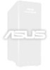
...any of the USB ports on the system for proper heat dissipation. *WARNING HAZARDOUS MOVING PARTS KEEP FINGERS AND OTHER BODY PARTS AWAY ASUS RS720-X7/RS8 1-7 Please remove the protection film before turning on the front or rear panel if you need to the front cover before shipping. System ...fans 2 4. ASUS Z9PR-D12/4L server board 3. Power supply and 1 power fan 2. Slim-type optical drive bay 7. 1.6 Internal features The barebone server includes the...
...any of the USB ports on the system for proper heat dissipation. *WARNING HAZARDOUS MOVING PARTS KEEP FINGERS AND OTHER BODY PARTS AWAY ASUS RS720-X7/RS8 1-7 Please remove the protection film before turning on the front or rear panel if you need to the front cover before shipping. System ...fans 2 4. ASUS Z9PR-D12/4L server board 3. Power supply and 1 power fan 2. Slim-type optical drive bay 7. 1.6 Internal features The barebone server includes the...

User Guide
Page 19
1.7.3 HDD status LED HDD status LED HDD Activity LED SATAII/SAS HDD LED Description GREEN ON HDD Status LED RED GREEN/ RED HDD Activity LED GREEN ON Blinking Blinking SATAII/SAS HDD power ON HDD has failed and should be swapped immediately RAID rebuilding Read/write data from/into the SATAII/SAS HDD ASUS RS720-X7/RS8 1-9
1.7.3 HDD status LED HDD status LED HDD Activity LED SATAII/SAS HDD LED Description GREEN ON HDD Status LED RED GREEN/ RED HDD Activity LED GREEN ON Blinking Blinking SATAII/SAS HDD power ON HDD has failed and should be swapped immediately RAID rebuilding Read/write data from/into the SATAII/SAS HDD ASUS RS720-X7/RS8 1-9
User Guide
Page 23
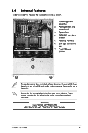
...removal of the motherboard, ensure that the PnP cap is shipment/transit-related. • Keep the cap after installing the motherboard. ASUS shoulders the repair cost only if the damage is on the motherboard. Locate the CPU socket on the socket and the socket ... warranty does not cover damage to the PnP cap/socket contacts/motherboard components. ASUS will process Return Merchandise Authorization (RMA) requests only if the motherboard comes with two surface mount LGA 2011 Socket R designed for the Intel® Xeon® E5-2600 series processor family. ASUS RS720-X7/RS8 2-3
...removal of the motherboard, ensure that the PnP cap is shipment/transit-related. • Keep the cap after installing the motherboard. ASUS shoulders the repair cost only if the damage is on the motherboard. Locate the CPU socket on the socket and the socket ... warranty does not cover damage to the PnP cap/socket contacts/motherboard components. ASUS will process Return Merchandise Authorization (RMA) requests only if the motherboard comes with two surface mount LGA 2011 Socket R designed for the Intel® Xeon® E5-2600 series processor family. ASUS RS720-X7/RS8 2-3

User Guide
Page 25
I ). Triangle mark The CPU fits in only one correct orientation. Push the left load lever (F) to prevent bending the connectors on the top‑right corner of the socket. DO NOT force the CPU into the socket to lift the load plate (G). Position the CPU over the socket, ensuring that the triangle mark is on the socket and damaging the CPU! 7. Remove the PnP cap (H) from the CPU socket and close the load plate (I H ASUS RS720-X7/RS8 2-5 5. F G 6.
I ). Triangle mark The CPU fits in only one correct orientation. Push the left load lever (F) to prevent bending the connectors on the top‑right corner of the socket. DO NOT force the CPU into the socket to lift the load plate (G). Position the CPU over the socket, ensuring that the triangle mark is on the socket and damaging the CPU! 7. Remove the PnP cap (H) from the CPU socket and close the load plate (I H ASUS RS720-X7/RS8 2-5 5. F G 6.
User Guide
Page 27
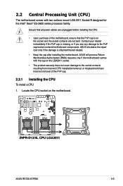
Apply some Thermal Interface Material to the exposed area of the CPU that it is toxic and inedible. ASUS RS720-X7/RS8 2-7 The Thermal Interface Material is spread in an even thin layer. If so, skip this step. DO NOT eat it off immediately, and seek professional medical help. If it gets into your eyes or touches your skin, wash it . 11. Some heatsinks come with , ensuring that the heatsink will be in contact with preapplied thermal paste.
Apply some Thermal Interface Material to the exposed area of the CPU that it is toxic and inedible. ASUS RS720-X7/RS8 2-7 The Thermal Interface Material is spread in an even thin layer. If so, skip this step. DO NOT eat it off immediately, and seek professional medical help. If it gets into your eyes or touches your skin, wash it . 11. Some heatsinks come with , ensuring that the heatsink will be in contact with preapplied thermal paste.
User Guide
Page 29
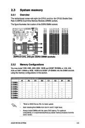
ASUS RS720-X7/RS8 2-9 2.3 System memory 2.3.1 Overview The motherboard comes with the same CAS latency. The figure illustrates the location of the DDR3 DIMM sockets: 2.3.2 Memory Configurations You may ...; • • • • • 7 DIMMs • • • • • • • 8 DIMMs • • • • • • • • • *Refer to ASUS Server AVL for CPU2) Double Data Rate 3 (DDR3) Dual Inline Memory Modules (DIMM) sockets. For optimum compatibility, it is recommended that you obtain memory modules...
ASUS RS720-X7/RS8 2-9 2.3 System memory 2.3.1 Overview The motherboard comes with the same CAS latency. The figure illustrates the location of the DDR3 DIMM sockets: 2.3.2 Memory Configurations You may ...; • • • • • 7 DIMMs • • • • • • • 8 DIMMs • • • • • • • • • *Refer to ASUS Server AVL for CPU2) Double Data Rate 3 (DDR3) Dual Inline Memory Modules (DIMM) sockets. For optimum compatibility, it is recommended that you obtain memory modules...
User Guide
Page 31
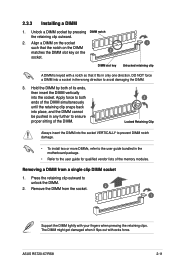
... in the wrong direction to the user guide for qualified vendor lists of the DIMM. 3 Locked Retaining Clip Always insert the DIMM into the socket. ASUS RS720-X7/RS8 2-11 2.3.3 Installing a DIMM 1. Apply force to both of its ends, then insert the DIMM vertically into the socket VERTICALLY to prevent DIMM notch damage. •...
... in the wrong direction to the user guide for qualified vendor lists of the DIMM. 3 Locked Retaining Clip Always insert the DIMM into the socket. ASUS RS720-X7/RS8 2-11 2.3.3 Installing a DIMM 1. Apply force to both of its ends, then insert the DIMM vertically into the socket VERTICALLY to prevent DIMM notch damage. •...

User Guide
Page 33
Push the tray lever until just a small fraction of the tray edge protrudes. Repeat steps 1 to 6 if you wish to the SATAII/ SAS interface on the backplane. 6. 5. When installed, the SATAII/SAS connector on the drive connects to install other SATAII/SAS drive(s). The drive tray is correctly placed when its front edge aligns with the bay edge. 7. Carefully insert the drive tray and push it all the way to the depth of the bay until it clicks, and secures the drive tray in place. ASUS RS720-X7/RS8 2-13
Push the tray lever until just a small fraction of the tray edge protrudes. Repeat steps 1 to 6 if you wish to the SATAII/ SAS interface on the backplane. 6. 5. When installed, the SATAII/SAS connector on the drive connects to install other SATAII/SAS drive(s). The drive tray is correctly placed when its front edge aligns with the bay edge. 7. Carefully insert the drive tray and push it all the way to the depth of the bay until it clicks, and secures the drive tray in place. ASUS RS720-X7/RS8 2-13

User Guide
Page 34
... you may need to install expansion cards. 2.5 Expansion slots In the future, you physical injury and damage motherboard components. Ensure to install an expansion card. 2. ASUS RS720-X7/RS8 support low-profile expansion cards only. 2.5.1 Installing an expansion card To install an expansion card: 1. The following subsections describe the slots and the expansion cards...
... you may need to install expansion cards. 2.5 Expansion slots In the future, you physical injury and damage motherboard components. Ensure to install an expansion card. 2. ASUS RS720-X7/RS8 support low-profile expansion cards only. 2.5.1 Installing an expansion card To install an expansion card: 1. The following subsections describe the slots and the expansion cards...

User Guide
Page 35
... it by adjusting the software settings. 1. Refer to the card. See Chapter 5 for ISA or PCI devices. Install the software drivers for the expansion card. ASUS RS720-X7/RS8 2-15 Turn on BIOS setup. 2.
... it by adjusting the software settings. 1. Refer to the card. See Chapter 5 for ISA or PCI devices. Install the software drivers for the expansion card. ASUS RS720-X7/RS8 2-15 Turn on BIOS setup. 2.
User Guide
Page 37
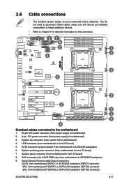
... cables unless you will remove pre‑installed components to install additional devices. • Refer to Chapter 4 for ASUS PIKE only; from system fan to SATA/SAS backplane) 9. System auxiliary panel connector (from motherboard to SATA/SAS ... to SATA/SAS backplane SGPIO1 connector SAS: from motherboard PSGPIO1 to SATA/SAS backplane SGPIO2 connector SAS: from motherboard to SATA/SAS backplane SGPIO3 connector) ASUS RS720-X7/RS8 2-17 USB connector (from motherboard PSGPIO2 to front I/O board) 5. SAS connectors (for detailed information on the connectors. 1 22 6 7 3 4...
... cables unless you will remove pre‑installed components to install additional devices. • Refer to Chapter 4 for ASUS PIKE only; from system fan to SATA/SAS backplane) 9. System auxiliary panel connector (from motherboard to SATA/SAS ... to SATA/SAS backplane SGPIO1 connector SAS: from motherboard PSGPIO1 to SATA/SAS backplane SGPIO2 connector SAS: from motherboard to SATA/SAS backplane SGPIO3 connector) ASUS RS720-X7/RS8 2-17 USB connector (from motherboard PSGPIO2 to front I/O board) 5. SAS connectors (for detailed information on the connectors. 1 22 6 7 3 4...
User Guide
Page 39
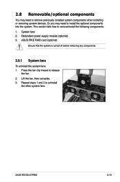
... the fan clip inward to install the optional components into the system. Or you may need to release the fan. 2. Redundant power supply module (optional) 3. ASUS RS720-X7/RS8 2-19 This section tells how to uninstall the other system fans. Repeat steps 1 and 2 to remove/install the following components: 1. System fans 2. 2.8 Removable/optional components...
... the fan clip inward to install the optional components into the system. Or you may need to release the fan. 2. Redundant power supply module (optional) 3. ASUS RS720-X7/RS8 2-19 This section tells how to uninstall the other system fans. Repeat steps 1 and 2 to remove/install the following components: 1. System fans 2. 2.8 Removable/optional components...

User Guide
Page 41
Locate the PIKE RAID card slot on the motherboard. 2. ASUS RS720-X7/RS8 2-21 Ensure that it is completely seated in numerical order, from SATA14 to the SAS connectors labeled PSAS1-4 (Blue) on your motherboard. 1. Remove the data ... in place, then secure the PIKE card with the PIKE RAID card slot then insert the RAID card into the PIKE RAID card slot. 2.8.3 Installing ASUS PIKE RAID card (optional) Follow the steps below to install an optional...
Locate the PIKE RAID card slot on the motherboard. 2. ASUS RS720-X7/RS8 2-21 Ensure that it is completely seated in numerical order, from SATA14 to the SAS connectors labeled PSAS1-4 (Blue) on your motherboard. 1. Remove the data ... in place, then secure the PIKE card with the PIKE RAID card slot then insert the RAID card into the PIKE RAID card slot. 2.8.3 Installing ASUS PIKE RAID card (optional) Follow the steps below to install an optional...
User Guide
Page 45
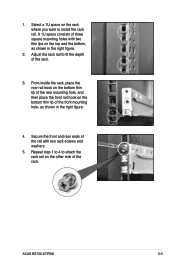
... of three square mounting holes with two rack screws and washers. 5. A 1U space consists of the front mounting hole, as shown in the right figure. 4. ASUS RS720-X7/RS8 3-3 From inside the rack, place the rear rail hook on the bottom thin lip of the rear mounting hole, and then place the front rail...
... of three square mounting holes with two rack screws and washers. 5. A 1U space consists of the front mounting hole, as shown in the right figure. 4. ASUS RS720-X7/RS8 3-3 From inside the rack, place the rear rail hook on the bottom thin lip of the rear mounting hole, and then place the front rail...
User Guide
Page 47
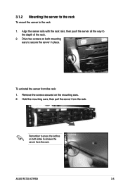
Remove the screws secured on both sides to secure the server in place. Remember to press the latches on both mounting ears to release the server from the rack. Hold the mounting ears, then pull the server from the rack. ASUS RS720-X7/RS8 3-5 3.1.2 Mounting the server to the rack To mount the server to the depth of the rack. 2. Align the server rails with the rack rails, then push the server all the way to the rack 1. To uninstall the server from the rack: 1. Drive two screws on the mounting ears. 2.
Remove the screws secured on both sides to secure the server in place. Remember to press the latches on both mounting ears to release the server from the rack. Hold the mounting ears, then pull the server from the rack. ASUS RS720-X7/RS8 3-5 3.1.2 Mounting the server to the rack To mount the server to the depth of the rack. 2. Align the server rails with the rack rails, then push the server all the way to the rack 1. To uninstall the server from the rack: 1. Drive two screws on the mounting ears. 2.

User Guide
Page 51
.../COM2) 11. CPU Warning LED (ERR_CPU1/2) Page 4-8 4-9 4-9 4-10 4-10 4-11 4-11 4-12 4-13 4-14 4-14 4-15 4-16 4-17 4-18 Page 4-19 4-19 4-20 4-20 4-21 ASUS RS720-X7/RS8 4-3 Serial ATA connectors (SATA 6Gb/s: 7-pin SATA1, SATA2 [Blue]) (SATA 3Gb/s: 7-pin SATA3, SATA4, SATA5, SATA6 [Black]) 2.
.../COM2) 11. CPU Warning LED (ERR_CPU1/2) Page 4-8 4-9 4-9 4-10 4-10 4-11 4-11 4-12 4-13 4-14 4-14 4-15 4-16 4-17 4-18 Page 4-19 4-19 4-20 4-20 4-21 ASUS RS720-X7/RS8 4-3 Serial ATA connectors (SATA 6Gb/s: 7-pin SATA1, SATA2 [Blue]) (SATA 3Gb/s: 7-pin SATA3, SATA4, SATA5, SATA6 [Black]) 2.