
User Guide
Page 1
VENTO 3600 Gaming Machine Chassis Kit User Guide 15-067008400
VENTO 3600 Gaming Machine Chassis Kit User Guide 15-067008400
User Guide
Page 6
...following parts: • Chapter 1: Product introduction This chapter gives a general description of the ASUS VENTO 3600 chassis kit. ASUS websites The ASUS website provides updated information on how to the ASUS contact information. 2. These documents are not part of the standard package. Refer to install ... that may have been added by -step instructions on ASUS hardware and software products. How this guide This user guide contains the general information and installation instructions for the ASUS VENTO 3600 chassis kit. vi About this guide is intended for experienced ...
...following parts: • Chapter 1: Product introduction This chapter gives a general description of the ASUS VENTO 3600 chassis kit. ASUS websites The ASUS website provides updated information on how to the ASUS contact information. 2. These documents are not part of the standard package. Refer to install ... that may have been added by -step instructions on ASUS hardware and software products. How this guide This user guide contains the general information and installation instructions for the ASUS VENTO 3600 chassis kit. vi About this guide is intended for experienced ...
User Guide
Page 9
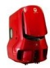
ASUS VENTO 3600 Product introduction Chapter 1 This chapter gives a general description of the ASUS VENTO 3600 chassis kit. The chapter lists the system features and introduces the front and rear panels, and the internal components.
ASUS VENTO 3600 Product introduction Chapter 1 This chapter gives a general description of the ASUS VENTO 3600 chassis kit. The chapter lists the system features and introduces the front and rear panels, and the internal components.
User Guide
Page 11
1.3 System specification Drive bays Expansion slots USB Audio ports Motherboard support Color options Dimensions Chassis material 4 x External 5.25-inch optical drive bays 1 x External 3.5-inch floppy disk drive bays 3 x Internal 3.5-inch hard disk drive bays 6 x PCI 1 x AGP Supports up to 4 USB 2.0 ports 1 x Headphone port 1 x Microphone port ATX form factor: 12" x 9.6" (30.5 cm x 24.4 cm) Green, blue, red 308 (w) x 527 (h) x 627 (d) mm 0.8 mm SECC ASUS VENTO 3600 1-3
1.3 System specification Drive bays Expansion slots USB Audio ports Motherboard support Color options Dimensions Chassis material 4 x External 5.25-inch optical drive bays 1 x External 3.5-inch floppy disk drive bays 3 x Internal 3.5-inch hard disk drive bays 6 x PCI 1 x AGP Supports up to 4 USB 2.0 ports 1 x Headphone port 1 x Microphone port ATX form factor: 12" x 9.6" (30.5 cm x 24.4 cm) Green, blue, red 308 (w) x 527 (h) x 627 (d) mm 0.8 mm SECC ASUS VENTO 3600 1-3

User Guide
Page 12
... 23 1. Expansion slot locks 12. Front panel 21. Side panel 10. HDD cage lock 14. Removable HDD cage (drives not included) 15. Side swivel 11. Chassis feet 17. 80 mm Auxiliary fan 18. LED 22. Magic Mask® 7. 5.25" Drive bay covers 8. FDD bay cover 1-4 Chapter 1: Product introduction Expansion slots 16...
... 23 1. Expansion slot locks 12. Front panel 21. Side panel 10. HDD cage lock 14. Removable HDD cage (drives not included) 15. Side swivel 11. Chassis feet 17. 80 mm Auxiliary fan 18. LED 22. Magic Mask® 7. 5.25" Drive bay covers 8. FDD bay cover 1-4 Chapter 1: Product introduction Expansion slots 16...

User Guide
Page 13
Front panel (external) Top panel Magic Mask® Power button USB 2.0 ports Microphone port Headphone port Front panel (internal) 5.25" Drive bay covers 3.5" Floppy disk drive bay cover ASUS VENTO 3600 1-5 The power button, LEDs, USB ports, and audio ports are located on the front panel. Flip the Magic Mask® to access the optical drive/s and floppy disk drive/s. 1.5 Front panel features The VENTO 3600 chassis displays a stylish front panel.
Front panel (external) Top panel Magic Mask® Power button USB 2.0 ports Microphone port Headphone port Front panel (internal) 5.25" Drive bay covers 3.5" Floppy disk drive bay cover ASUS VENTO 3600 1-5 The power button, LEDs, USB ports, and audio ports are located on the front panel. Flip the Magic Mask® to access the optical drive/s and floppy disk drive/s. 1.5 Front panel features The VENTO 3600 chassis displays a stylish front panel.

User Guide
Page 14
... air duct to pull cool air directly to the components. Power supply unit slot Cable management kit Rear panel I /O ports, seven full-length expansion slots, chassis cover screw holes, a vent for the system fan, and a slot for the installation of internal components. Side vent for air duct Side swivel Cool LED...
... air duct to pull cool air directly to the components. Power supply unit slot Cable management kit Rear panel I /O ports, seven full-length expansion slots, chassis cover screw holes, a vent for the system fan, and a slot for the installation of internal components. Side vent for air duct Side swivel Cool LED...

User Guide
Page 15
Motherboard mounting panel 4. Expansion slot covers 5. Power supply slot 2. 120 mm system fan vent 3. 1.8 Internal features The VENTO 3600 chassis includes the basic components as shown. 1 6 2 3 7 4 8 5 9 1. Chassis intrusion sensor 6. 5.25-inch drive bays 7. 3.5-inch FDD bay 8. Detachable HDD cage 9. 80 mm Auxiliary fan (hidden) ASUS VENTO 3600 1-7
Motherboard mounting panel 4. Expansion slot covers 5. Power supply slot 2. 120 mm system fan vent 3. 1.8 Internal features The VENTO 3600 chassis includes the basic components as shown. 1 6 2 3 7 4 8 5 9 1. Chassis intrusion sensor 6. 5.25-inch drive bays 7. 3.5-inch FDD bay 8. Detachable HDD cage 9. 80 mm Auxiliary fan (hidden) ASUS VENTO 3600 1-7

User Guide
Page 18
Floppy disk drive(s) 6. Do not move or lift the chassis with the cable management kit. 2-2 Chapter 2: Basic installation Hard disk drive 4. 5.25-inch drive(s) 5. Power supply unit (PSU) 3. Pull up the cable management kit to... 1 downward to release the bottom tabs. 2 The cable management kit is not a handle. Expansion card(s) Tool You need to install the following components to the VENTO 3600 chassis kit. 1. 2.1 Preparation Basic components to install You need a Phillips (cross) screw driver to install some system components. 2.2 Removing the side panel To remove the ...
Floppy disk drive(s) 6. Do not move or lift the chassis with the cable management kit. 2-2 Chapter 2: Basic installation Hard disk drive 4. 5.25-inch drive(s) 5. Power supply unit (PSU) 3. Pull up the cable management kit to... 1 downward to release the bottom tabs. 2 The cable management kit is not a handle. Expansion card(s) Tool You need to install the following components to the VENTO 3600 chassis kit. 1. 2.1 Preparation Basic components to install You need a Phillips (cross) screw driver to install some system components. 2.2 Removing the side panel To remove the ...
User Guide
Page 19
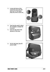
Push the side panel to release the side panel. 5. 3. Keep the screw for later use. 4. Turn the side swivel to about 45º clockwise to the direction of the arrow. 4 5 6. Tilt the side panel, then lift and set aside. ASUS VENTO 3600 2-3 Locate and remove three screws that secure the left side cover to the chassis.
Push the side panel to release the side panel. 5. 3. Keep the screw for later use. 4. Turn the side swivel to about 45º clockwise to the direction of the arrow. 4 5 6. Tilt the side panel, then lift and set aside. ASUS VENTO 3600 2-3 Locate and remove three screws that secure the left side cover to the chassis.
User Guide
Page 21
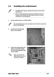
Lay the chassis down on the chassis. 3. ASUS VENTO 3600 2-5 Make sure that you cover the surface with the mounting plate holes on the side panel. 2. Locate the mounting plate holes on a stable surface. Orient ... the I/O shield matches the slot for detailed instructions on installing a CPU, heatsink and fan assembly, memory, and other components to protect the paint on the chassis. 2.4 Installing the motherboard • The VENTO 3600 supports standard ATX and micro ATX (mATX) motherboards. • Refer to the motherboard user guide for rear panel connectors.
Lay the chassis down on the chassis. 3. ASUS VENTO 3600 2-5 Make sure that you cover the surface with the mounting plate holes on the side panel. 2. Locate the mounting plate holes on a stable surface. Orient ... the I/O shield matches the slot for detailed instructions on installing a CPU, heatsink and fan assembly, memory, and other components to protect the paint on the chassis. 2.4 Installing the motherboard • The VENTO 3600 supports standard ATX and micro ATX (mATX) motherboards. • Refer to the motherboard user guide for rear panel connectors.
User Guide
Page 22
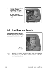
Hard disk drive cage Configure your hard disk drive as Master/Slave device before installing it to set the drive as a Master/Slave device. 2-6 Chapter 2: Basic installation 4. The photo shows the motherboard installed in the chassis. 2.5 Installing a hard disk drive The chassis kit supports two IDE/ Serial ATA hard disk drives through a detachable hard disk drive cage. Refer to the HDD documentation on how to the chassis. Drive the required number of screws with a Phillips screwdriver to secure the motherboard to the chassis.
Hard disk drive cage Configure your hard disk drive as Master/Slave device before installing it to set the drive as a Master/Slave device. 2-6 Chapter 2: Basic installation 4. The photo shows the motherboard installed in the chassis. 2.5 Installing a hard disk drive The chassis kit supports two IDE/ Serial ATA hard disk drives through a detachable hard disk drive cage. Refer to the HDD documentation on how to the chassis. Drive the required number of screws with a Phillips screwdriver to secure the motherboard to the chassis.

User Guide
Page 23
Insert an HDD into the upper bay of the arrow. Press down the HDD cage lock. 2. Secure the HDD to the cage with the HDD cage screw holes. 4. Place the HDD cage on both sides of the cage. Make sure that the HDD screw holes are aligned with two screws on a flat surface. 3. Screw holes ASUS VENTO 3600 2-7 Carefully pull the cage out of the chassis in the direction of the cage. 2.5.1 Installing an IDE hard disk drive To install an I D E hard disk drive: 1.
Insert an HDD into the upper bay of the arrow. Press down the HDD cage lock. 2. Secure the HDD to the cage with the HDD cage screw holes. 4. Place the HDD cage on both sides of the cage. Make sure that the HDD screw holes are aligned with two screws on a flat surface. 3. Screw holes ASUS VENTO 3600 2-7 Carefully pull the cage out of the chassis in the direction of the cage. 2.5.1 Installing an IDE hard disk drive To install an I D E hard disk drive: 1.

User Guide
Page 24
Re-install the HDD cage to the hard disk drive. 2-8 Chapter 2: Basic installation Slide in the direction of the arrow until it snaps to indicate that it is secured to the bay assembly rails. 6. Carefully push the HDD cage in the HDD cage to the chassis. 5 6 6. Refer to the motherboard user guide before connecting an IDE cable to the chassis. Connect a 4-pin power plug from the power supply unit to the IDE connector at the back of the drive. 7. Connect a 40-pin IDE cable to the power connector at the back of the drive. 5.
Re-install the HDD cage to the hard disk drive. 2-8 Chapter 2: Basic installation Slide in the direction of the arrow until it snaps to indicate that it is secured to the bay assembly rails. 6. Carefully push the HDD cage in the HDD cage to the chassis. 5 6 6. Refer to the motherboard user guide before connecting an IDE cable to the chassis. Connect a 4-pin power plug from the power supply unit to the IDE connector at the back of the drive. 7. Connect a 40-pin IDE cable to the power connector at the back of the drive. 5.

User Guide
Page 26
The system comes with four 5.25-inch drive bays located on the upper front part of the Magic Mask® to do so may install an optical drive on the uppermost bay. Failure to release the lock. 2-10 Chapter 2: Basic installation To install an optical drive: 1. 2.6 Installing 5.25-inch drives Make sure to the motherboard and other system components! Gently push the marked portion of the chassis. 1 2 3 4 2.6.1 Installing an optical drive You may cause severe damage to unplug the power cable before installing or removing any system components.
The system comes with four 5.25-inch drive bays located on the upper front part of the Magic Mask® to do so may install an optical drive on the uppermost bay. Failure to release the lock. 2-10 Chapter 2: Basic installation To install an optical drive: 1. 2.6 Installing 5.25-inch drives Make sure to the motherboard and other system components! Gently push the marked portion of the chassis. 1 2 3 4 2.6.1 Installing an optical drive You may cause severe damage to unplug the power cable before installing or removing any system components.
User Guide
Page 27
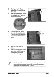
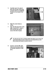
... optical drive into the bay to secure the optical drive without screws. Align the screw holes as shown. 6. ASUS VENTO 3600 2-11 Slide the drive bay lock to the right, towards the sign, to the chassis front panel. 5. 2. However, we recommend that allows you still drive screws into the bay, then push it inward...
... optical drive into the bay to secure the optical drive without screws. Align the screw holes as shown. 6. ASUS VENTO 3600 2-11 Slide the drive bay lock to the right, towards the sign, to the chassis front panel. 5. 2. However, we recommend that allows you still drive screws into the bay, then push it inward...

User Guide
Page 28
... 2: Basic installation 2.6.2 Installing additional 5.25-inch drive(s) You may install additional 5.25-inch optical drives, zip, or floppy disk drives in and out of the chassis until it to the drive bay. Configure your optical drive as Master/Slave device before installing it is removed. 4.
... 2: Basic installation 2.6.2 Installing additional 5.25-inch drive(s) You may install additional 5.25-inch optical drives, zip, or floppy disk drives in and out of the chassis until it to the drive bay. Configure your optical drive as Master/Slave device before installing it is removed. 4.
User Guide
Page 29
... lock to the right, towards the sign to lock the drive bay and to secure the optical drive without screws. ASUS VENTO 3600 2-13 Carefully insert the optical drive into the bay to the chassis front panel. 6. 5. However, we recommend that allows you still drive screws into the bay, then push it inward until...
... lock to the right, towards the sign to lock the drive bay and to secure the optical drive without screws. ASUS VENTO 3600 2-13 Carefully insert the optical drive into the bay to the chassis front panel. 6. 5. However, we recommend that allows you still drive screws into the bay, then push it inward until...
User Guide
Page 31
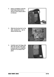
ASUS VENTO 3600 2-15 Using a screwdriver, push the knock down metal cover in and out of the chassis until it is completely flushed to unlock the drive bay. 4. Slide the drive bay lock to the right, towards the sign to the chassis front panel. Carefully insert the floppy disk drive into the bay, then push it inward until it is removed. 3. 3.
ASUS VENTO 3600 2-15 Using a screwdriver, push the knock down metal cover in and out of the chassis until it is completely flushed to unlock the drive bay. 4. Slide the drive bay lock to the right, towards the sign to the chassis front panel. Carefully insert the floppy disk drive into the bay, then push it inward until it is removed. 3. 3.
User Guide
Page 33
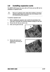
... PCI slots and one AGP slot for the card. 2. ASUS VENTO 3600 2-17 Remove the metal cover opposite the slot that you want to use . 3. Make sure to both the motherboard and the components. Push out the green lock tab. 4. 2.8 Installing expansion cards The VENTO 3600 chassis kit comes with it and make the necessary hardware...
... PCI slots and one AGP slot for the card. 2. ASUS VENTO 3600 2-17 Remove the metal cover opposite the slot that you want to use . 3. Make sure to both the motherboard and the components. Push out the green lock tab. 4. 2.8 Installing expansion cards The VENTO 3600 chassis kit comes with it and make the necessary hardware...
