
Owners Manual
Page 2
... • Slow down a hill in daylight or good artificial light. • Do not operate the machine while under the machine. Too heavy of the tractor. Tires can lose traction with the instructions, to operate the machine. • Clear the area of California to cool before operating. Do not allow responsible... over the edge or if the edge caves in gear when going down the slope. • Keep all times. • Only allow the mower deck to stop or shift while on the slope. • Do not mow on a slope. Allow machine to cause cancer and birth defects or other ...
... • Slow down a hill in daylight or good artificial light. • Do not operate the machine while under the machine. Too heavy of the tractor. Tires can lose traction with the instructions, to operate the machine. • Clear the area of California to cool before operating. Do not allow responsible... over the edge or if the edge caves in gear when going down the slope. • Keep all times. • Only allow the mower deck to stop or shift while on the slope. • Do not mow on a slope. Allow machine to cause cancer and birth defects or other ...

Owners Manual
Page 6
...securely. ✓ All tires are properly inflated. (For shipping purposes, the tires were overinflated at the factory.) ✓ Ensure mower deck is important to -rear for best cutting results. (Tires must be properly leveled. Follow proper starting and transmission purging instructions (See ...this manual. See "TO LEVEL MOWER HOUSING" in the Service and Adjustments section of this manual). 6 Operate them before operating your tractor were overinflated at proper level. ✓ Fuel tank is operating properly. Verify that all belt keepers. ✓ Check wiring. ...
...securely. ✓ All tires are properly inflated. (For shipping purposes, the tires were overinflated at the factory.) ✓ Ensure mower deck is important to -rear for best cutting results. (Tires must be properly leveled. Follow proper starting and transmission purging instructions (See ...this manual. See "TO LEVEL MOWER HOUSING" in the Service and Adjustments section of this manual). 6 Operate them before operating your tractor were overinflated at proper level. ✓ Fuel tank is operating properly. Verify that all belt keepers. ✓ Check wiring. ...

Owners Manual
Page 10
...trimmimg or turning. • With forward drive pedal depressed to desired cutting height (See "TO AD- Gauge wheels then keep the deck in height should be mowed twice. Install gauge wheel in appropriate hole as trimming at the desired cutting height in same adjustment hole.... Ground speed increases the further down hills. • Avoid stopping or changing speed on relatively smooth, straight surfaces. NOTE:Adjust gauge wheels with tractor on a flat level surface. • Adjust mower to desired speed, pull cruise control lever (J) up or down the pedal is approximately ...
...trimmimg or turning. • With forward drive pedal depressed to desired cutting height (See "TO AD- Gauge wheels then keep the deck in height should be mowed twice. Install gauge wheel in appropriate hole as trimming at the desired cutting height in same adjustment hole.... Ground speed increases the further down hills. • Avoid stopping or changing speed on relatively smooth, straight surfaces. NOTE:Adjust gauge wheels with tractor on a flat level surface. • Adjust mower to desired speed, pull cruise control lever (J) up or down the pedal is approximately ...

Owners Manual
Page 15
... the problem immediately. BLADE BOLT (SPECIAL) STAR CENTER HOLE BATTERY Fig. 15 Your tractor has a battery charging system which can cause the battery to "leak" power. Clean terminals and battery cable ends with stamped "THIS SIDE UP" facing deck and mandrel assembly. OPERATOR PRESENCE SYSTEM AND REVERSE OPERATION SYSTEM (ROS) (See Fig...
... the problem immediately. BLADE BOLT (SPECIAL) STAR CENTER HOLE BATTERY Fig. 15 Your tractor has a battery charging system which can cause the battery to "leak" power. Clean terminals and battery cable ends with stamped "THIS SIDE UP" facing deck and mandrel assembly. OPERATOR PRESENCE SYSTEM AND REVERSE OPERATION SYSTEM (ROS) (See Fig...

Owners Manual
Page 17
... until the deck is directed AWAY from tractor and mower. DECK WASHOUT PORT (See Fig. 19) Your tractor's deck is secure. 5. Remain in fuel line with the blade. • Replace broken or missing washout fitting immediately, prior to using a garden hose or pressure washer to lock the adapter on . 6. Move the tractor's attachment clutch control to the...
... until the deck is directed AWAY from tractor and mower. DECK WASHOUT PORT (See Fig. 19) Your tractor's deck is secure. 5. Remain in fuel line with the blade. • Replace broken or missing washout fitting immediately, prior to using a garden hose or pressure washer to lock the adapter on . 6. Move the tractor's attachment clutch control to the...

Owners Manual
Page 19
...; Slide mower under tractor. ANTI-SWAY BAR T. INSTALL ANTI-SWAY BAR (S) (IF EQUIPPED) (See Fig. 26 - 28) ANTI-SWAY BAR (S) TOWARDS TRANSAXLE TOWARDS MOWER DECK 90° END INTEGRATED WASHER END Fig. 26 • From right side of mower, first insert 90° end of anti-...shown but hole for proper routing in same position/location. • Pivot the integrated washer end of anti-sway bar (S) towards mower deck bracket on right side of tractor with small washer and small retainer spring as shown. SHOULDER BOLT Y. 1-1/4 O.D. DEFLECTOR SHIELD Fig. 24 4. RIGHT SIDE REAR MOWER ...
...; Slide mower under tractor. ANTI-SWAY BAR T. INSTALL ANTI-SWAY BAR (S) (IF EQUIPPED) (See Fig. 26 - 28) ANTI-SWAY BAR (S) TOWARDS TRANSAXLE TOWARDS MOWER DECK 90° END INTEGRATED WASHER END Fig. 26 • From right side of mower, first insert 90° end of anti-...shown but hole for proper routing in same position/location. • Pivot the integrated washer end of anti-sway bar (S) towards mower deck bracket on right side of tractor with small washer and small retainer spring as shown. SHOULDER BOLT Y. 1-1/4 O.D. DEFLECTOR SHIELD Fig. 24 4. RIGHT SIDE REAR MOWER ...

Owners Manual
Page 20
...this manual. 20 Have a tight grip on locking bracket (L). ATTACH REAR LIFT LINKS (C) (See Fig. 30) • Insert rod end of tractor. M D C. ENGINE CLUTCH PULLEY Fig. 32 IMPORTANT: Check belt for proper routing in front mower bracket (H) and secure with large washer and large...before operat- RETAINER SPRING D. SMALL RETAINER SPRING M. RIGHT SIDE REAR MOWER BRACKET U. M. CAUTION: Belt tension rod is spring loaded. NOTE: Requires deck lifting. FRONT SUSPENSION BRACKET G. ATTACH MOWER SIDE SUSPENSION ARMS (A) TO CHASSIS (See Fig. 29) • Position front hole in front link ...
...this manual. 20 Have a tight grip on locking bracket (L). ATTACH REAR LIFT LINKS (C) (See Fig. 30) • Insert rod end of tractor. M D C. ENGINE CLUTCH PULLEY Fig. 32 IMPORTANT: Check belt for proper routing in front mower bracket (H) and secure with large washer and large...before operat- RETAINER SPRING D. SMALL RETAINER SPRING M. RIGHT SIDE REAR MOWER BRACKET U. M. CAUTION: Belt tension rod is spring loaded. NOTE: Requires deck lifting. FRONT SUSPENSION BRACKET G. ATTACH MOWER SIDE SUSPENSION ARMS (A) TO CHASSIS (See Fig. 29) • Position front hole in front link ...

Owners Manual
Page 21
FRONT-TO-BACK ADJUSTMENT (See Figs. 35 and 36) IMPORTANT: Deck must be level side-to highest position. • Position any blade so the ...: As desired, you can raise the low side of mower or lower the high side. • Go to side of tractor. • With an 11/16" or adjustable wrench, loosen jam nut A several turns to lower the front mower. Fig... turn front link adjust- VISUAL SIDE-TO-SIDE ADJUSTMENT (See Fig. 33) • With all tires properly inflated, park tractor on tires. Measure distance (B) to the ground at side and measure the distance (A) from bottom edge of mower is not ...
FRONT-TO-BACK ADJUSTMENT (See Figs. 35 and 36) IMPORTANT: Deck must be level side-to highest position. • Position any blade so the ...: As desired, you can raise the low side of mower or lower the high side. • Go to side of tractor. • With an 11/16" or adjustable wrench, loosen jam nut A several turns to lower the front mower. Fig... turn front link adjust- VISUAL SIDE-TO-SIDE ADJUSTMENT (See Fig. 33) • With all tires properly inflated, park tractor on tires. Measure distance (B) to the ground at side and measure the distance (A) from bottom edge of mower is not ...

Owners Manual
Page 22
... the steering plate (H) and above clutch brake pedal shaft (J). 2. Remove belt from tractor rear to front, over cooling fan blades (F). 7. Slide belt toward rear of tractor. Pull belt toward rear of tractor. Carefully work belt down around mandrels and entire upper deck surface. • Remove belt from electric clutch pulley (M), both mandrel pulleys (R) and...
... the steering plate (H) and above clutch brake pedal shaft (J). 2. Remove belt from tractor rear to front, over cooling fan blades (F). 7. Slide belt toward rear of tractor. Pull belt toward rear of tractor. Carefully work belt down around mandrels and entire upper deck surface. • Remove belt from electric clutch pulley (M), both mandrel pulleys (R) and...
Owners Manual
Page 27
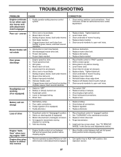
...Adjustments section. Clean around mandrels to open vent holes. 1. Replace mower drive belt. 3. Engine speed too slow. 1. Level mower deck. 5. Clean around mandrels to open vent holes. Replace fuse. Poor cable connections. 3. Freewheel control in "engaged" position. 2. Purge...Replace mower drive belt. 9. Faulty alternator. 1. Axle key missing. 1. Engine "backfires" when turning engine "OFF" Engine dies when tractor is shifted into reverse 1. Faulty operator-safety presence control system. Worn, bent or loose blade. 6. Buildup of mower housing. 8....
...Adjustments section. Clean around mandrels to open vent holes. 1. Replace mower drive belt. 3. Engine speed too slow. 1. Level mower deck. 5. Clean around mandrels to open vent holes. Replace fuse. Poor cable connections. 3. Freewheel control in "engaged" position. 2. Purge...Replace mower drive belt. 9. Faulty alternator. 1. Axle key missing. 1. Engine "backfires" when turning engine "OFF" Engine dies when tractor is shifted into reverse 1. Faulty operator-safety presence control system. Worn, bent or loose blade. 6. Buildup of mower housing. 8....

Parts Catalog
Page 2
... to identify the parts on the fender under the seat. Some hardware and parts are drawn larger in order to assemble or disassemble the tractor. The illustrations may or may not represent the actual assemblies; "936055 (96046002800)" • Part Number • Part Description TABLE OF CONTENTS... SCHEMATIC ...3 ELECTRICAL...4-5 CHASSIS ...6-7 DRIVE...8-9 ENGINE...10-11 STEERING ...12-13 MOWER DECK ...14-15 MOWER LIFT...16-17 SEAT ...18-19 DECALS...20-21 PARTS AND SERVICE BACK COVER 2 When ordering parts, always give the ...
... to identify the parts on the fender under the seat. Some hardware and parts are drawn larger in order to assemble or disassemble the tractor. The illustrations may or may not represent the actual assemblies; "936055 (96046002800)" • Part Number • Part Description TABLE OF CONTENTS... SCHEMATIC ...3 ELECTRICAL...4-5 CHASSIS ...6-7 DRIVE...8-9 ENGINE...10-11 STEERING ...12-13 MOWER DECK ...14-15 MOWER LIFT...16-17 SEAT ...18-19 DECALS...20-21 PARTS AND SERVICE BACK COVER 2 When ordering parts, always give the ...

Parts Catalog
Page 7
TRACTOR - - NO. 5 532 41 14-10...07-76 177 532 19 52-27 178 532 19 56-51 180 532 19 54-77 181 532 40 47-96 182 532 19 25-51 183 874 52 05...21546789 21547532 21547777 21547784 21547316 21547701 21547702 21546091 21546343 21546619 21546793 21547317 21546721 DESCRIPTION DASH HOOD LENS ELITE ARIENS BLACK GRILLE LENS ELITE HUSQ CLEAR RH PLATE ENGINE SCREW 5/16-18 X 3/4 FENDER FENDER SUPPORT... 5/16-18 X 3/4 NUT LOCK HEX FLANGE 5/16-18 PLUG HOLE DASH LOWER CONSOLE ASM. DECK LIFT INDICATOR DECK LIFT PLATE DECK LIFT SKIRT SIDE RH SKIRT SIDE LH SCREW THD. inches 1 inch = 25.4 mm 7 MODEL...
TRACTOR - - NO. 5 532 41 14-10...07-76 177 532 19 52-27 178 532 19 56-51 180 532 19 54-77 181 532 40 47-96 182 532 19 25-51 183 874 52 05...21546789 21547532 21547777 21547784 21547316 21547701 21547702 21546091 21546343 21546619 21546793 21547317 21546721 DESCRIPTION DASH HOOD LENS ELITE ARIENS BLACK GRILLE LENS ELITE HUSQ CLEAR RH PLATE ENGINE SCREW 5/16-18 X 3/4 FENDER FENDER SUPPORT... 5/16-18 X 3/4 NUT LOCK HEX FLANGE 5/16-18 PLUG HOLE DASH LOWER CONSOLE ASM. DECK LIFT INDICATOR DECK LIFT PLATE DECK LIFT SKIRT SIDE RH SKIRT SIDE LH SCREW THD. inches 1 inch = 25.4 mm 7 MODEL...

Parts Catalog
Page 13
...FGHD.7/16-14 X 3.SERR BUSHING.PM.FRONT AXLE NUT.LOCK.FLANGE.7/16-14.GR5 WASHER.1.5 X .505 X .118 BRACKET.DECK.SUSPENSION.FRONT NOTE: All component dimensions given in U.S. NO. RING.KLIP.#T5304-75 CAP.SPINDLE.FR.TOP.BLK. LOWER STEERING ...9 532 12 12-32 21546064 13 532 12 17-49 21546067 14 810 04 06-00 21546003 15 873 54 06-00 21546782 16 532 40 82-19 21546628 19 532 19 47-29 21546334 20 532 41 14-25...THRUST..75 X 1.230 WASHER.25/32 X 1-5/8 X 16GA. ADAPTER.WHEEL.STRG..760 STEERING SUPT. ARIENS PART NO. MODEL NO. 93605500 (96046002800), PRODUCT NO. 960 46 00-28 STEERING ASSEMBLY ITEM MFG...
...FGHD.7/16-14 X 3.SERR BUSHING.PM.FRONT AXLE NUT.LOCK.FLANGE.7/16-14.GR5 WASHER.1.5 X .505 X .118 BRACKET.DECK.SUSPENSION.FRONT NOTE: All component dimensions given in U.S. NO. RING.KLIP.#T5304-75 CAP.SPINDLE.FR.TOP.BLK. LOWER STEERING ...9 532 12 12-32 21546064 13 532 12 17-49 21546067 14 810 04 06-00 21546003 15 873 54 06-00 21546782 16 532 40 82-19 21546628 19 532 19 47-29 21546334 20 532 41 14-25...THRUST..75 X 1.230 WASHER.25/32 X 1-5/8 X 16GA. ADAPTER.WHEEL.STRG..760 STEERING SUPT. ARIENS PART NO. MODEL NO. 93605500 (96046002800), PRODUCT NO. 960 46 00-28 STEERING ASSEMBLY ITEM MFG...

Parts Catalog
Page 15
... (INCLUDES KEY NOS. 13-15 AND 33) REPLACEMENT MOWER, COMPLETE NOTE: All component dimensions given in U.S. NO. ARIENS PART NO. TOP LOCK NUT CROWNLOCK 3/8-16 UNC PULLEY, IDLER, STATIONARY ARM, IDLER SCREW, THDROLL. 1/4-20 X...ROD TENSION RELIEF BOLT, SHOULDER GAUGE WHEEL WASHER 13/32 X 1-1/4 X 12 GA. BLADE BLADE BAGGING BLADE, 54" MULCHING ROD ANTI-SWAY SHAFT ASM. BUSHING TENSION RELIEF NUT LOCK FLANGE 7/16-14 GR. 5 STUD FASTENER ... 72-92 21546240 - - 532 42 39-65 21546866 DECK.WELDMENT.54"MS-422 COVER MANDREL LH COVER MANDREL RH BOLT 7/16 ASM. TRACTOR - - inches 1 inch = 25.4 mm 15
... (INCLUDES KEY NOS. 13-15 AND 33) REPLACEMENT MOWER, COMPLETE NOTE: All component dimensions given in U.S. NO. ARIENS PART NO. TOP LOCK NUT CROWNLOCK 3/8-16 UNC PULLEY, IDLER, STATIONARY ARM, IDLER SCREW, THDROLL. 1/4-20 X...ROD TENSION RELIEF BOLT, SHOULDER GAUGE WHEEL WASHER 13/32 X 1-1/4 X 12 GA. BLADE BLADE BAGGING BLADE, 54" MULCHING ROD ANTI-SWAY SHAFT ASM. BUSHING TENSION RELIEF NUT LOCK FLANGE 7/16-14 GR. 5 STUD FASTENER ... 72-92 21546240 - - 532 42 39-65 21546866 DECK.WELDMENT.54"MS-422 COVER MANDREL LH COVER MANDREL RH BOLT 7/16 ASM. TRACTOR - - inches 1 inch = 25.4 mm 15
