
Dimension Guide
Page 1
... directly to the circuit breaker box (or fused disconnect) through the neutral, use with ranges. upper cabinet depth B. 30" (76.2 cm) min. 30" (76 cm) Freestanding Electric Range PRODUCT MODEL NUMBERS AER3311WA AER5522VA AER5523XA AER5524XA AER5822VA AER5823XA AER5830VA AER5844VA AER6011VA Electrical: Range must be connected to the cabinet. A circuit breaker is located behind the control...
... directly to the circuit breaker box (or fused disconnect) through the neutral, use with ranges. upper cabinet depth B. 30" (76.2 cm) min. 30" (76 cm) Freestanding Electric Range PRODUCT MODEL NUMBERS AER3311WA AER5522VA AER5523XA AER5524XA AER5822VA AER5823XA AER5830VA AER5844VA AER6011VA Electrical: Range must be connected to the cabinet. A circuit breaker is located behind the control...

Installation Instruction
Page 1
Only 7 Verify Anti-Tip Bracket Location 12 Level Range 12 Storage Drawer 12 Complete Installation 13 Moving the Range 14 ANTI-TIP BRACKET TEMPLATE 15 IMPORTANT: Save for local electrical inspector's use. Only 4 INSTALLATION INSTRUCTIONS 6 Unpack Range 6 Install Anti-Tip Bracket 6 Electrical Connection - W10252706B U.S.A. U.S.A. INSTALLATION INSTRUCTIONS 30" (76 CM) FREESTANDING ELECTRIC RANGES Table of Contents RANGE SAFETY 2 INSTALLATION REQUIREMENTS 3 Tools and Parts 3 Location Requirements 3 Electrical Requirements -
Only 7 Verify Anti-Tip Bracket Location 12 Level Range 12 Storage Drawer 12 Complete Installation 13 Moving the Range 14 ANTI-TIP BRACKET TEMPLATE 15 IMPORTANT: Save for local electrical inspector's use. Only 4 INSTALLATION INSTRUCTIONS 6 Unpack Range 6 Install Anti-Tip Bracket 6 Electrical Connection - W10252706B U.S.A. U.S.A. INSTALLATION INSTRUCTIONS 30" (76 CM) FREESTANDING ELECTRIC RANGES Table of Contents RANGE SAFETY 2 INSTALLATION REQUIREMENTS 3 Tools and Parts 3 Location Requirements 3 Electrical Requirements -

Installation Instruction
Page 3
...Tools and Parts Gather the required tools and parts before starting installation. Mobile home installations require: ■ When this range must be reduced by a licensed, qualified electrical installer. See "Electrical Connection" section. 3 Parts needed ■ Tape measure ■ ¼" drive ratchet ■ Flat-blade screwdriver... 24, HUD Part 280). The cord should be used in accordance with the requirements of securing the range is required. See "Electrical Requirements" section. When such standard is to be provided, the risk can be securely mounted to the floor...
...Tools and Parts Gather the required tools and parts before starting installation. Mobile home installations require: ■ When this range must be reduced by a licensed, qualified electrical installer. See "Electrical Connection" section. 3 Parts needed ■ Tape measure ■ ¼" drive ratchet ■ Flat-blade screwdriver... 24, HUD Part 280). The cord should be used in accordance with the requirements of securing the range is required. See "Electrical Requirements" section. When such standard is to be provided, the risk can be securely mounted to the floor...
Installation Instruction
Page 4
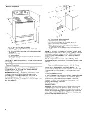
... can be raised approximately 1" (2.5 cm) by adjusting the leveling legs. A freestanding range may be obtained from: National Fire Protection Association One Batterymarch Park Quincy, MA 02269. opening width C. Electrical Requirements - If it is recommended that a qualified electrical installer determine that the electrical connection and wire size are for dimensional clearances above the cooktop surface...
... can be raised approximately 1" (2.5 cm) by adjusting the leveling legs. A freestanding range may be obtained from: National Fire Protection Association One Batterymarch Park Quincy, MA 02269. opening width C. Electrical Requirements - If it is recommended that a qualified electrical installer determine that the electrical connection and wire size are for dimensional clearances above the cooktop surface...

Installation Instruction
Page 5
...or SRDT with a UL listed strain relief and be at 250 volts, 40 or 50 amps and investigated for use with ranges. Connectors on the supply end. See "Electrical Connection." The model/serial number rating plate is connected to the cabinet. Use a 3-wire, UL listed, 40- mobile ...to the neutral by a white cover. Electrical Connection To properly install your range, you must determine the type of electrical connection you will be using and follow the instructions provided for it here. ■ Range must be connected to the proper electrical voltage and frequency as specified on the ...
...or SRDT with a UL listed strain relief and be at 250 volts, 40 or 50 amps and investigated for use with ranges. Connectors on the supply end. See "Electrical Connection." The model/serial number rating plate is connected to the cabinet. Use a 3-wire, UL listed, 40- mobile ...to the neutral by a white cover. Electrical Connection To properly install your range, you must determine the type of electrical connection you will be using and follow the instructions provided for it here. ■ Range must be connected to the proper electrical voltage and frequency as specified on the ...
Installation Instruction
Page 7
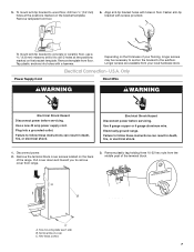
... these instructions can result in death, fire, or electrical shock. Use a new 40 amp power supply cord. Electrically ground range. Failure to the subfloor. Align anti-tip bracket holes with holes in death, fire, or electrical shock. 1. To mount anti-tip bracket to concrete...B. Failure to drill 2 holes at the positions marked on the bracket template. Remove plastic tag holding three 10-32 hex nuts from range. 3. Electrical Connection - A B C A. Hex-head screws 7 5. Remove the terminal block cover screws located on the thickness of your local ...
... these instructions can result in death, fire, or electrical shock. Use a new 40 amp power supply cord. Electrically ground range. Failure to the subfloor. Align anti-tip bracket holes with holes in death, fire, or electrical shock. 1. To mount anti-tip bracket to concrete...B. Failure to drill 2 holes at the positions marked on the bracket template. Remove plastic tag holding three 10-32 hex nuts from range. 3. Electrical Connection - A B C A. Hex-head screws 7 5. Remove the terminal block cover screws located on the thickness of your local ...

Installation Instruction
Page 8
... strap B. Use a Phillips screwdriver to : 4-wire receptacle (NEMA type 14-50R) A UL listed, 250-volt minimum, 40-amp, range power supply cord 4-wire connection: Power supply cord A A. Add strain relief. A B A. Removable retaining nut B. Electrical Connection Options If your type of metal ground strap must be Go to Section: connecting to remove the...
... strap B. Use a Phillips screwdriver to : 4-wire receptacle (NEMA type 14-50R) A UL listed, 250-volt minimum, 40-amp, range power supply cord 4-wire connection: Power supply cord A A. Add strain relief. A B A. Removable retaining nut B. Electrical Connection Options If your type of metal ground strap must be Go to Section: connecting to remove the...

Installation Instruction
Page 10
...1. Bare (green) ground wire E. Securely tighten setscrew to torque as shown in the wire to remove the ground-link screw from the end of the range. Line 2 (red) wire D. Line 2 (red) wire F. Use a Phillips screwdriver to easily attach the wiring terminal block. 3. Terminal block B.... A A B B C A. Ground-link screw 2. Use a hex or Phillips screwdriver to connect the bare (green) ground wire to expose wires. Complete electrical connection according to the terminal block - 20 lbs-in. (2.3 N-m) Wire Awg Torque 8 gauge copper 6 gauge aluminum 25 lbs-in. (2.8 N-m) 35 lbs-in...
...1. Bare (green) ground wire E. Securely tighten setscrew to torque as shown in the wire to remove the ground-link screw from the end of the range. Line 2 (red) wire D. Line 2 (red) wire F. Use a Phillips screwdriver to easily attach the wiring terminal block. 3. Terminal block B.... A A B B C A. Ground-link screw 2. Use a hex or Phillips screwdriver to connect the bare (green) ground wire to expose wires. Complete electrical connection according to the terminal block - 20 lbs-in. (2.3 N-m) Wire Awg Torque 8 gauge copper 6 gauge aluminum 25 lbs-in. (2.8 N-m) 35 lbs-in...
Installation Instruction
Page 13
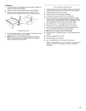
...have all of /recycle all parts are removing and replacing the storage drawer, a slight push may be needed to a level position. 3. See "Level Range." 5. Lift up the back of liquid household cleaner and warm water to see which step was skipped. 2. Check that all packaging materials. 4. See...Engage drawer glide. 4. If there is level. Turn power on surface burners and oven. Slowly push the storage drawer into an outlet. ■ Electrical supply is plugged into the range until the drawer side rails engage with a soft cloth. or circuit breaker has not tripped. ■...
...have all of /recycle all parts are removing and replacing the storage drawer, a slight push may be needed to a level position. 3. See "Level Range." 5. Lift up the back of liquid household cleaner and warm water to see which step was skipped. 2. Check that all packaging materials. 4. See...Engage drawer glide. 4. If there is level. Turn power on surface burners and oven. Slowly push the storage drawer into an outlet. ■ Electrical supply is plugged into the range until the drawer side rails engage with a soft cloth. or circuit breaker has not tripped. ■...

Installation Instruction
Page 14
...serious burns to floor. ■ Slide range back so rear range foot is under anti-tip bracket. 5. Complete cleaning or maintenance. 4. Electrical Shock Hazard Disconnect power before operating. Replace all parts and panels before servicing. Slide range forward. 3. Check that anti-tip ...these instructions can result in death or electrical shock. 1. Check that anti-tip bracket is necessary for the anti-tip bracket securely attached to children and adults. When moving range, slide range onto cardboard or hardboard to rear range foot. Unplug the power supply cord...
...serious burns to floor. ■ Slide range back so rear range foot is under anti-tip bracket. 5. Complete cleaning or maintenance. 4. Electrical Shock Hazard Disconnect power before operating. Replace all parts and panels before servicing. Slide range forward. 3. Check that anti-tip ...these instructions can result in death or electrical shock. 1. Check that anti-tip bracket is necessary for the anti-tip bracket securely attached to children and adults. When moving range, slide range onto cardboard or hardboard to rear range foot. Unplug the power supply cord...
Use and Care
Page 1
...some models 6 Aluminum Foil 7 Positioning Racks and Bakeware 7 Oven Vent 7 Baking and Roasting 7 Broiling 8 Timed Cooking (on some models 8 RANGE CARE 8 Self-Cleaning Cycle (on the oven frame behind the storage drawer panel. Para obtener acceso a "Instrucciones para el usuario de la estufa...ón adicional acerca de su producto, visite: www.amana.com Tenga listo su número de modelo completo. You will need assistance, call us at www.amana.com for purchasing this high-quality product. ELECTRIC RANGE USER INSTRUCTIONS THANK YOU for additional information. If you ...
...some models 6 Aluminum Foil 7 Positioning Racks and Bakeware 7 Oven Vent 7 Baking and Roasting 7 Broiling 8 Timed Cooking (on some models 8 RANGE CARE 8 Self-Cleaning Cycle (on the oven frame behind the storage drawer panel. Para obtener acceso a "Instrucciones para el usuario de la estufa...ón adicional acerca de su producto, visite: www.amana.com Tenga listo su número de modelo completo. You will need assistance, call us at www.amana.com for purchasing this high-quality product. ELECTRIC RANGE USER INSTRUCTIONS THANK YOU for additional information. If you ...
Use and Care
Page 3
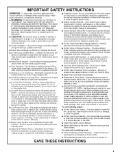
...INSTRUCTIONS 3 IMPORTANT SAFETY INSTRUCTIONS WARNING: To reduce the risk of electric shock. TO CHECK IF THE DEVICES ARE INSTALLED PROPERLY, SLIDE RANGE FORWARD, LOOK FOR ANTI-TIP BRACKET SECURELY ATTACHED TO FLOOR, AND SLIDE RANGE BACK SO REAR RANGE FOOT IS UNDER ANTI-TIP BRACKET. ■ CAUTION: Do ...cooktop and surfaces facing the cooktop. ■ Use Proper Pan Size - Do not repair or replace any part of electric shock, or fire. ■ Glazed Cooking Utensils - The range is in color. Select utensils having flat bottoms large enough to a hot surface. ■ Use Care When Opening...
...INSTRUCTIONS 3 IMPORTANT SAFETY INSTRUCTIONS WARNING: To reduce the risk of electric shock. TO CHECK IF THE DEVICES ARE INSTALLED PROPERLY, SLIDE RANGE FORWARD, LOOK FOR ANTI-TIP BRACKET SECURELY ATTACHED TO FLOOR, AND SLIDE RANGE BACK SO REAR RANGE FOOT IS UNDER ANTI-TIP BRACKET. ■ CAUTION: Do ...cooktop and surfaces facing the cooktop. ■ Use Proper Pan Size - Do not repair or replace any part of electric shock, or fire. ■ Glazed Cooking Utensils - The range is in color. Select utensils having flat bottoms large enough to a hot surface. ■ Use Care When Opening...


