
Ferrari 5000 User's Guide
Page 5
...or disposed of electric shock from the equipment when not in fire. For more information on the Waste from children. Do not disassemble or dispose of used batteries. Disposal instructions Do not throw this equipment during lightning or thunderstorms. Warning! For safety reasons, do... www.eiae.org. Follow local regulations when disposing of them away from Electrical and Electronics Equipment (WEEE) regulations, visit http://global.acer.com/about/environmental.htm. To minimize pollution and ensure utmost protection of fire or explosion. Batteries may present a risk of the ...
...or disposed of electric shock from the equipment when not in fire. For more information on the Waste from children. Do not disassemble or dispose of used batteries. Disposal instructions Do not throw this equipment during lightning or thunderstorms. Warning! For safety reasons, do... www.eiae.org. Follow local regulations when disposing of them away from Electrical and Electronics Equipment (WEEE) regulations, visit http://global.acer.com/about/environmental.htm. To minimize pollution and ensure utmost protection of fire or explosion. Batteries may present a risk of the ...

Ferrari 5000 User's Guide
Page 93
... TOUTE EXPOSITION AUX RAYONS. EVITE EXPONERSE A LOS RAYOS. VARO! Nevertheless, some pixels may occasionally misfire or appear as black or red dots. Reverse engineering or disassembly is located on the recorded image and does not constitute a malfunction. VARNING: LASERSTRÅLNING NÅR DENNA DEL ÅR ÖPPNAD ÅLÅ TUIJOTA SÅ...
... TOUTE EXPOSITION AUX RAYONS. EVITE EXPONERSE A LOS RAYOS. VARO! Nevertheless, some pixels may occasionally misfire or appear as black or red dots. Reverse engineering or disassembly is located on the recorded image and does not constitute a malfunction. VARNING: LASERSTRÅLNING NÅR DENNA DEL ÅR ÖPPNAD ÅLÅ TUIJOTA SÅ...

Ferrari 5000 Service Guide
Page 8
...Acer OrbiCam 21 Launching the Acer OrbiCam 21 Changing the Acer OrbiCam Settings 22 Using the Acer OrbiCam as Webcam 24 Acer Empowering Technology 27 Empowering Technology Password 27 Acer eDataSecurity Management 27 Acer eLock Management 29 Acer ePerformance Management 30 Acer eRecovery Management 31 Acer eSettings Management 32 Acer ePower Management 33 Acer ePresentation Management 35 Using the System Utilities 36 Acer...Chapter 3 Machine Disassembly and Replacement 62 General Information 63 Before You Begin 63 Disassembly Procedure Flowchart 64 Disassembly Procedure 66 ...
...Acer OrbiCam 21 Launching the Acer OrbiCam 21 Changing the Acer OrbiCam Settings 22 Using the Acer OrbiCam as Webcam 24 Acer Empowering Technology 27 Empowering Technology Password 27 Acer eDataSecurity Management 27 Acer eLock Management 29 Acer ePerformance Management 30 Acer eRecovery Management 31 Acer eSettings Management 32 Acer ePower Management 33 Acer ePresentation Management 35 Using the System Utilities 36 Acer...Chapter 3 Machine Disassembly and Replacement 62 General Information 63 Before You Begin 63 Disassembly Procedure Flowchart 64 Disassembly Procedure 66 ...

Ferrari 5000 Service Guide
Page 71
... • Flat head screw driver • Hexagonal driver • Tweezers NOTE: The screws for maintenance and troubleshooting. To disassemble the computer, you remove the stripe cover, please be careful not to avoid mismatch when putting back the components. During the... disassembly process, group the screws with the corresponding components to scrape the cover. Chapter 3 62 Chapter 3 Machine Disassembly and Replacement This chapter contains step-by-step procedures on how to disassemble the notebook for the different components vary in...
... • Flat head screw driver • Hexagonal driver • Tweezers NOTE: The screws for maintenance and troubleshooting. To disassemble the computer, you remove the stripe cover, please be careful not to avoid mismatch when putting back the components. During the... disassembly process, group the screws with the corresponding components to scrape the cover. Chapter 3 62 Chapter 3 Machine Disassembly and Replacement This chapter contains step-by-step procedures on how to disassemble the notebook for the different components vary in...

Ferrari 5000 Service Guide
Page 72
General Information Before You Begin Before proceeding with the disassembly procedure, you fasten the screws on the wrong location, the long screws may cause irrecoverable damage to make sure that: 1. The battery pack is removed. ... length. The system and all power and signal cables from the system are powered off. 2. NOTE: There are several types of screws together during service disassembling.
General Information Before You Begin Before proceeding with the disassembly procedure, you fasten the screws on the wrong location, the long screws may cause irrecoverable damage to make sure that: 1. The battery pack is removed. ... length. The system and all power and signal cables from the system are powered off. 2. NOTE: There are several types of screws together during service disassembling.

Ferrari 5000 Service Guide
Page 73
... Bracket ODD and ODD Board J*2 Keyboard D*4 LCD Module J*7 on the fron B*2 on the front J*3 on bottom D*14 on the entire disassembly and reassembly and instructs you how to remove the components. Disassembly Procedure Flowchart The flowchart gives you a graphic representation on bottom J*3 Hinge Cover Launch Board Launch Cable Upper Case Assembly Touchpad...
... Bracket ODD and ODD Board J*2 Keyboard D*4 LCD Module J*7 on the fron B*2 on the front J*3 on bottom D*14 on the entire disassembly and reassembly and instructs you how to remove the components. Disassembly Procedure Flowchart The flowchart gives you a graphic representation on bottom J*3 Hinge Cover Launch Board Launch Cable Upper Case Assembly Touchpad...

Ferrari 5000 Service Guide
Page 75
Remove the DIMM cover. 3. Pop out the memory modules then remove it . Release the two screws fastening the DIMM cover. 2. Detach the HDD cover from the main unit. Remove the four screws holding the HDD cover. 2. Removing the Memory Module 1. Removing the HDD Module/Mini PCI Card/ODD Module 1. Slide the battery latch and release the battery pack then remove it . Chapter 3 66 Slide the battery lock. 2. Disassembly Procedure Removing the Battery Pack 1.
Remove the DIMM cover. 3. Pop out the memory modules then remove it . Release the two screws fastening the DIMM cover. 2. Detach the HDD cover from the main unit. Remove the four screws holding the HDD cover. 2. Removing the Memory Module 1. Removing the HDD Module/Mini PCI Card/ODD Module 1. Slide the battery latch and release the battery pack then remove it . Chapter 3 66 Slide the battery lock. 2. Disassembly Procedure Removing the Battery Pack 1.
Ferrari 5000 Service Guide
Page 78
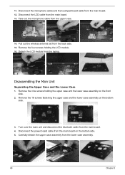
Remove the four screws holding the upper case and the lower case assembly on the front side. 2. 11. Disassembling the Main Unit Separating the Upper Case and the Lower Case 1. Turn over the main unit and disconnect the bluetooth cable from the main board. ...
Remove the four screws holding the upper case and the lower case assembly on the front side. 2. 11. Disassembling the Main Unit Separating the Upper Case and the Lower Case 1. Turn over the main unit and disconnect the bluetooth cable from the main board. ...

Ferrari 5000 Service Guide
Page 79
... the touchpad to the touchpad board bracket. 9. Remove the four screws fastening the touchpad bracket. 11. Detach the touchpad board from the upper case. 12. Disassembling the Upper Case Assembly 1. Detach the touchpad bracket from the bracket. 10. Disconnect the bluetooth cable from the touchpad. 6.
... the touchpad to the touchpad board bracket. 9. Remove the four screws fastening the touchpad bracket. 11. Detach the touchpad board from the upper case. 12. Disassembling the Upper Case Assembly 1. Detach the touchpad bracket from the bracket. 10. Disconnect the bluetooth cable from the touchpad. 6.

Ferrari 5000 Service Guide
Page 80
Take the power board out of the lower case. 3. Detach the dummy expand card from the modem board. 8. Disassembling the Lower Case Assembly 1. Remove the two screws holding the modem board. 9. Disconnect the modem cable from the lower case. 6. Remove the two screws fastening ...
Take the power board out of the lower case. 3. Detach the dummy expand card from the modem board. 8. Disassembling the Lower Case Assembly 1. Remove the two screws holding the modem board. 9. Disconnect the modem cable from the lower case. 6. Remove the two screws fastening ...

Ferrari 5000 Service Guide
Page 82
... two screws holding the wireless antenna set to the LCD cover. 73 Chapter 3 Remove the four screws fastening the LCD assembly to the LCD module. 3. Disassembling the LCD Module 1. Disconnect the CCD cable and the LCD cable. 7. Tear off the foil attach onto the wireless antenna set to the LCD cover...
... two screws holding the wireless antenna set to the LCD cover. 73 Chapter 3 Remove the four screws fastening the LCD assembly to the LCD module. 3. Disassembling the LCD Module 1. Disconnect the CCD cable and the LCD cable. 7. Tear off the foil attach onto the wireless antenna set to the LCD cover...

Ferrari 5000 Service Guide
Page 84
Disconnect the CCD cable from the CCD cover as well. 22. Remove the left LCD bracket to HDD on the other side. 3. Disassembling the External Modules HDD Module 1. Remove the two screws holding the HDD bracket to the HDD. 2. 21. Take out the CCD hinge from the CCD ...
Disconnect the CCD cable from the CCD cover as well. 22. Remove the left LCD bracket to HDD on the other side. 3. Disassembling the External Modules HDD Module 1. Remove the two screws holding the HDD bracket to the HDD. 2. 21. Take out the CCD hinge from the CCD ...


