Ferrari 3000 Service Guide
Page 7
Table of Contents Chpater 1 System Specifications 1 Features 1 System Block Diagram 3 Board Layout 4 Top View 4 Bottom View 5 Outlook View 6 Front Open View 6 Front Panel 7 Left Panel 8 Right Panel 9 Rear Panel 10 Bottom Panel 11 Indicators 12 Using ... Removing the HDD Module 51 Removing the Wireless LAN Card 51 Removing the LCD Module 52 Disassembling the Main Unit 53 Remove the function key board and the keyboard 53 Separate the main unit into the logic upper and the logic lower assembly .53 Disassembling the logic upper assembly 54 Disassembling...
Table of Contents Chpater 1 System Specifications 1 Features 1 System Block Diagram 3 Board Layout 4 Top View 4 Bottom View 5 Outlook View 6 Front Open View 6 Front Panel 7 Left Panel 8 Right Panel 9 Rear Panel 10 Bottom Panel 11 Indicators 12 Using ... Removing the HDD Module 51 Removing the Wireless LAN Card 51 Removing the LCD Module 52 Disassembling the Main Unit 53 Remove the function key board and the keyboard 53 Separate the main unit into the logic upper and the logic lower assembly .53 Disassembling the logic upper assembly 54 Disassembling...
Ferrari 3000 Service Guide
Page 30
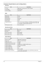
... by setup manual Built-in CPU 512KB Always enabled Always enabled Fixed in write-back Specification Specification AMD AthlonTM XP-M built-in 0MB (no on-board memory) 2 sockets 1024MB 2048MB (by two 1024MB SO-DIMM module) DDR Synchronous DRAM 333 MHz 2.5V 200-pin soDIMM You can install memory modules in...
... by setup manual Built-in CPU 512KB Always enabled Always enabled Fixed in write-back Specification Specification AMD AthlonTM XP-M built-in 0MB (no on-board memory) 2 sockets 1024MB 2048MB (by two 1024MB SO-DIMM module) DDR Synchronous DRAM 333 MHz 2.5V 200-pin soDIMM You can install memory modules in...

Ferrari 3000 Service Guide
Page 35
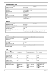
... Left panel No ZV support Yes (IRQ10) Specification Smart Card Reader Item Chipset Number of slot Location PCMCIA chip built-in 1 Front side Specification System Board Major Chips Item Core logic VGA LAN IEEE 1394 USB 2.0 Controller VIA KN400 (AMD AthlonTM XP-M processor, VIA KN400+VIA VT8235) ATI M9+X VIA VT8235...
... Left panel No ZV support Yes (IRQ10) Specification Smart Card Reader Item Chipset Number of slot Location PCMCIA chip built-in 1 Front side Specification System Board Major Chips Item Core logic VGA LAN IEEE 1394 USB 2.0 Controller VIA KN400 (AMD AthlonTM XP-M processor, VIA KN400+VIA VT8235) ATI M9+X VIA VT8235...
Ferrari 3000 Service Guide
Page 36
... work simultaneously Specification NS 87570 C4 DARFON 84/85 key Yes No Note: Internal and external keyboard can not work simultaneously by software specification. System Board Major Chips Item Super I/O controller MODEM Blue tooth Wireless 802.11g PCMCIA Audio Four-in parallel 14.8V LCD Item Vendor & model name Mechanical Specifications...
... work simultaneously Specification NS 87570 C4 DARFON 84/85 key Yes No Note: Internal and external keyboard can not work simultaneously by software specification. System Board Major Chips Item Super I/O controller MODEM Blue tooth Wireless 802.11g PCMCIA Audio Four-in parallel 14.8V LCD Item Vendor & model name Mechanical Specifications...
Ferrari 3000 Service Guide
Page 55
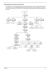
... servicing. Start Battery Hx2 HDD Door Hx2 Dimm Door HDD Module Memory Hx2 Mx3 Keyboard Ox4 Middle Cover Sx4 LCD Module Hx3 Function Key Board Hx2 PCI Door ODD Module Wireless LAN Card Touchpad Main Unit Assembly Front Bezel Sx19 Hx2 Ux3 Cx4 ODD Bracket Fx2 ODD... Board ODD Logic Upper Assembly Qx4 Touchpad Shielding Touchpad Board Hx4 Touchpad Holder Touchpad Cable (FFC) Logic Lower Assembly Ax4 Hx1 Hx1 Main Board CPU Dimm Dx3 4-in that need to remove the system board, you on the entire disassembly sequence and instructs you...
... servicing. Start Battery Hx2 HDD Door Hx2 Dimm Door HDD Module Memory Hx2 Mx3 Keyboard Ox4 Middle Cover Sx4 LCD Module Hx3 Function Key Board Hx2 PCI Door ODD Module Wireless LAN Card Touchpad Main Unit Assembly Front Bezel Sx19 Hx2 Ux3 Cx4 ODD Bracket Fx2 ODD... Board ODD Logic Upper Assembly Qx4 Touchpad Shielding Touchpad Board Hx4 Touchpad Holder Touchpad Cable (FFC) Logic Lower Assembly Ax4 Hx1 Hx1 Main Board CPU Dimm Dx3 4-in that need to remove the system board, you on the entire disassembly sequence and instructs you...

Ferrari 3000 Service Guide
Page 61
... the keyboard. 5. Turn over the keyboard. Separate the main unit into the logic upper and the logic lower assembly 1. Chapter 3 53 Disconnect function key board connector 3. Detach the front bezel from the logic lower assembly. Turn over the unit and remove the two screws as the picture shows. 6. Remove the... two screws. Unscrew the three screws holding the function key board. 4. Take the wireless antenna out of the hook on the function key board. 2. Disassembling the Main Unit Remove the function key...
... the keyboard. 5. Turn over the keyboard. Separate the main unit into the logic upper and the logic lower assembly 1. Chapter 3 53 Disconnect function key board connector 3. Detach the front bezel from the logic lower assembly. Turn over the unit and remove the two screws as the picture shows. 6. Remove the... two screws. Unscrew the three screws holding the function key board. 4. Take the wireless antenna out of the hook on the function key board. 2. Disassembling the Main Unit Remove the function key...
Ferrari 3000 Service Guide
Page 62
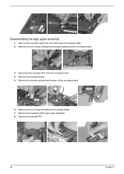
Disassembling the logic upper assembly 1. Remove the four screws holding the touchpad shielding and the touchpad board. 3. Remove the touchpad board. 5. Remove the wireless and bluetooth button off the logic upper assembly. 8. Remove the four screws that fasten the touchpad holder. 7. Take out the touchpad cable from the touchpad board. 4. Remove the touchpad off the touchpad board. 6. Disconnect the touchpad FFC from the small hook on touchpad holder. 2. Disconnect touchpad FFC. 54 Chapter 3
Disassembling the logic upper assembly 1. Remove the four screws holding the touchpad shielding and the touchpad board. 3. Remove the touchpad board. 5. Remove the wireless and bluetooth button off the logic upper assembly. 8. Remove the four screws that fasten the touchpad holder. 7. Take out the touchpad cable from the touchpad board. 4. Remove the touchpad off the touchpad board. 6. Disconnect the touchpad FFC from the small hook on touchpad holder. 2. Disconnect touchpad FFC. 54 Chapter 3
Ferrari 3000 Service Guide
Page 63
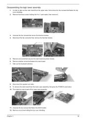
...the thermal module. 5. Disconnect the speaker set cable. 9. Then take out the main board from the lower case assembly, first press the PCMCIA card button. 10. Remove one screw that fastens the main board. 7. Remove one screw holding the 4-in-1 card reader, then remove it. 3.... Chapter 3 55 Remove another screw that secures the main board as picture shows. 6. Unscrew the four screws that fasten the HDD ...
...the thermal module. 5. Disconnect the speaker set cable. 9. Then take out the main board from the lower case assembly, first press the PCMCIA card button. 10. Remove one screw that fastens the main board. 7. Remove one screw holding the 4-in-1 card reader, then remove it. 3.... Chapter 3 55 Remove another screw that secures the main board as picture shows. 6. Unscrew the four screws that fasten the HDD ...
Ferrari 3000 Service Guide
Page 70
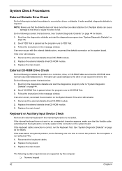
... diagnostics diskette and start the diagnostics program (refer to be tested. If an error occurs, reconnect the connector on the system board. Replace the main board. If the keyboard cable connection is to "System Diagnostic Diskette" on page 44. 2. Replace the keyboard. 3. NOTE: Make...isolate the problem to correct the problem. If an error occurs with the internal diskette drive, reconnect the diskette connector on the System board. Reconnect the external diskette drive/CD-ROM module. 2. See "System Diagnostic Diskette" on page 44 for details. Reconnect the keyboard ...
... diagnostics diskette and start the diagnostics program (refer to be tested. If an error occurs, reconnect the connector on the system board. Replace the main board. If the keyboard cable connection is to "System Diagnostic Diskette" on page 44. 2. Replace the keyboard. 3. NOTE: Make...isolate the problem to correct the problem. If an error occurs with the internal diskette drive, reconnect the diskette connector on the System board. Reconnect the external diskette drive/CD-ROM module. 2. See "System Diagnostic Diskette" on page 44 for details. Reconnect the keyboard ...
Ferrari 3000 Service Guide
Page 71
... operations, show error messages on the computer using each of the following list: T "Check the Battery Pack" on page 64 Chapter 4 63 Go to main board. 2. Press F2 in the test items. 3. A loose connection can cause an error. Connect the power adapter and check that power is fully installed into the...
... operations, show error messages on the computer using each of the following list: T "Check the Battery Pack" on page 64 Chapter 4 63 Go to main board. 2. Press F2 in the test items. 3. A loose connection can cause an error. Connect the power adapter and check that power is fully installed into the...
Ferrari 3000 Service Guide
Page 72
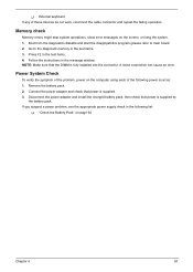
...If the voltage is still less than 50% of time. 64 Chapter 4 If the the PS/2 mouse does not work, then check if the main board to switch board FPC is applied to the touchpad pointer. If the FFC on touch pad PCB connects properly, then check if LS851 JP1 Pin6=5V are...the touch pad still does not work , do the following figure 3. Power off the computer. 2. Re-install the battery pack. If yes, then replace switch board. Check out the Power Management in the screen for both battery and adapter. 4. Repeat the steps 1 and 2, for Current Power Source and Total Battery Power...
...If the voltage is still less than 50% of time. 64 Chapter 4 If the the PS/2 mouse does not work, then check if the main board to switch board FPC is applied to the touchpad pointer. If the FFC on touch pad PCB connects properly, then check if LS851 JP1 Pin6=5V are...the touch pad still does not work , do the following figure 3. Power off the computer. 2. Re-install the battery pack. If yes, then replace switch board. Check out the Power Management in the screen for both battery and adapter. 4. Repeat the steps 1 and 2, for Current Power Source and Total Battery Power...
Ferrari 3000 Service Guide
Page 74
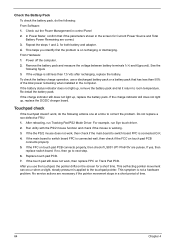
... Default Settings" in BIOS Setup Utility. "Load Default Settings" in BIOS Setup Utility. Dikette drive Hard disk drive Main board. 66 Chapter 4 RTC battery Run BIOS Setup Utility to reconfigure system, then reboot system. Default configuration used Invalid System Configuration Data Operating system not found ... Setup Utility to reconfigure system time, then reboot system. Index of Error Messages Error Message List Error Messages Struck Key System CMOS checksum bad - Main board. Default configuration used Real time clock error Previous boot incomplete -
... Default Settings" in BIOS Setup Utility. "Load Default Settings" in BIOS Setup Utility. Dikette drive Hard disk drive Main board. 66 Chapter 4 RTC battery Run BIOS Setup Utility to reconfigure system, then reboot system. Default configuration used Invalid System Configuration Data Operating system not found ... Setup Utility to reconfigure system time, then reboot system. Index of Error Messages Error Message List Error Messages Struck Key System CMOS checksum bad - Main board. Default configuration used Real time clock error Previous boot incomplete -
Ferrari 3000 Service Guide
Page 75
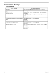
... connector Hard disk drive LCD cable LCD inverter LCD Main board Power-on indicator turns on an external CRT. But you can see POST on and LCD is blank. Main board Chapter 4 67 Power-on indicator turns on LCD during POST. Main board. shown on and LCD is connected tightly and correctly. Reconnect... the LCD connectors. LCD cable LCD inverter LCD Main board Power-on indicator turns on page 63 Ensure every connector is blank. Power source (battery pack and power adapter.) See "Power System Check" on and a ...
... connector Hard disk drive LCD cable LCD inverter LCD Main board Power-on indicator turns on an external CRT. But you can see POST on and LCD is blank. Main board Chapter 4 67 Power-on indicator turns on LCD during POST. Main board. shown on and LCD is connected tightly and correctly. Reconnect... the LCD connectors. LCD cable LCD inverter LCD Main board Power-on indicator turns on page 63 Ensure every connector is blank. Power source (battery pack and power adapter.) See "Power System Check" on and a ...
Ferrari 3000 Service Guide
Page 77
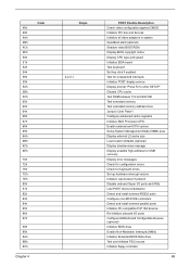
... devices Initialize all video adapters in system QuietBoot start (optional) Shadow video BIOS ROM Display BIOS copyright notice Display CPU type and speed Initialize EISA board Test keyboard Set key click if enabled Test for unexpected interrupts Initialize POST display service Display prompt "Press F2 to enter SETUP" Disable CPU cache...
... devices Initialize all video adapters in system QuietBoot start (optional) Shadow video BIOS ROM Display BIOS copyright notice Display CPU type and speed Initialize EISA board Test keyboard Set key click if enabled Test for unexpected interrupts Initialize POST display service Display prompt "Press F2 to enter SETUP" Disable CPU cache...
Ferrari 3000 Service Guide
Page 78
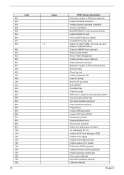
... PnP Option ROMs Clear parity checkers Display MultiBoot menu Clear screen (optional) Check virus and backup reminders Try to UserPatch2 Build MPTABLE for multi-processor boards Install CD ROM for boot Clear huge ES segment register Fixup Multi Processor table Search for errors POST done- Check for SMART drive (optional) Shadow...
... PnP Option ROMs Clear parity checkers Display MultiBoot menu Clear screen (optional) Check virus and backup reminders Try to UserPatch2 Build MPTABLE for multi-processor boards Install CD ROM for boot Clear huge ES segment register Fixup Multi Processor table Search for errors POST done- Check for SMART drive (optional) Shadow...
Ferrari 3000 Service Guide
Page 80
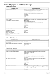
...function key doesn't work ). Verify OS in Sequence Power source (battery pack and power adapter). Action in the HDD. Battery pack Power adapter CPU Main board In Windows XP operating system, hold and press the power switch for more than 4 seconds. LCD cable LCD inverter LCD Main...'t work LCD is overheat (Heat sink or fan). The system cannot power-off or on . LCD cable LCD inverter LCD Main board Reconnect the LCD cable LCD cable LCD Main board Indicator-Related Symptoms Symptom / Error Indicator incorrectly remains off . Battery pack AC adapter See if the thermal module is too dark...
...function key doesn't work ). Verify OS in Sequence Power source (battery pack and power adapter). Action in the HDD. Battery pack Power adapter CPU Main board In Windows XP operating system, hold and press the power switch for more than 4 seconds. LCD cable LCD inverter LCD Main...'t work LCD is overheat (Heat sink or fan). The system cannot power-off or on . LCD cable LCD inverter LCD Main board Reconnect the LCD cable LCD cable LCD Main board Indicator-Related Symptoms Symptom / Error Indicator incorrectly remains off . Battery pack AC adapter See if the thermal module is too dark...
Ferrari 3000 Service Guide
Page 81
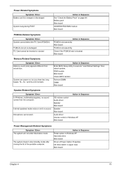
... the Battery Pack" on , but you hear two long beeps: "B--, B--" and the LCD is damaged. RAM module Main board Check BIOS revision Reinsert DIMM DIMM Main board Speaker-Related Symptoms Symptom / Error In Windows, multimedia programs, no sound. System can 't be inserted or ejected Action in Windows... XP Main board Power Management-Related Symptoms Symptom / Error The system will not enter hibernation mode The system doesn't enter standby mode after closing the...
... the Battery Pack" on , but you hear two long beeps: "B--, B--" and the LCD is damaged. RAM module Main board Check BIOS revision Reinsert DIMM DIMM Main board Speaker-Related Symptoms Symptom / Error In Windows, multimedia programs, no sound. System can 't be inserted or ejected Action in Windows... XP Main board Power Management-Related Symptoms Symptom / Error The system will not enter hibernation mode The system doesn't enter standby mode after closing the...

Ferrari 3000 Service Guide
Page 82
... Refresh battery (continue use battery until power off, then charge battery). Run printer self-test. Printer driver Printer cable Printer Main board Enter BIOS Setup Utility to execute "Load Default Settings" then reboot the system. Check if the battery is low. Reconnect hard disk.../CD-ROM drives. Device driver Device cable Device Main board Keyboard/Touchpad-Related Symptoms Symptom / Error Keyboard (one or more keys) does not work . Power Management-Related Symptoms Symptom / Error Action...
... Refresh battery (continue use battery until power off, then charge battery). Run printer self-test. Printer driver Printer cable Printer Main board Enter BIOS Setup Utility to execute "Load Default Settings" then reboot the system. Check if the battery is low. Reconnect hard disk.../CD-ROM drives. Device driver Device cable Device Main board Keyboard/Touchpad-Related Symptoms Symptom / Error Keyboard (one or more keys) does not work . Power Management-Related Symptoms Symptom / Error Action...
Ferrari 3000 Service Guide
Page 83
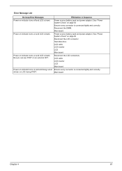
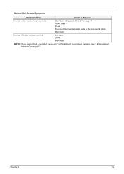
Modem/LAN-Related Symptoms Symptom / Error Action in Sequence Internal modem does not work correctly Lan cable Driver Main board NOTE: If you cannot find a symptom or an error in this list and the problem remains, see "Undetermined Problems" on page 44. Chapter 4 75 Main board Internal LAN does not work correctly. See "System Diagnostic Diskette" on page 77. Phone cable Driver Reconnect the Internal modem cable to the main board tightly.
Modem/LAN-Related Symptoms Symptom / Error Action in Sequence Internal modem does not work correctly Lan cable Driver Main board NOTE: If you cannot find a symptom or an error in this list and the problem remains, see "Undetermined Problems" on page 44. Chapter 4 75 Main board Internal LAN does not work correctly. See "System Diagnostic Diskette" on page 77. Phone cable Driver Reconnect the Internal modem cable to the main board tightly.
Ferrari 3000 Service Guide
Page 84
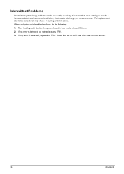
.... If any FRU. 3. When analyzing an intermittent problem, do not replace any error is detected, do the following: 1. Run the diagnostic test for the system board in loop mode at least 10 times. 2.
.... If any FRU. 3. When analyzing an intermittent problem, do not replace any error is detected, do the following: 1. Run the diagnostic test for the system board in loop mode at least 10 times. 2.


