
RAID Installation Guide
Page 1
... a RAID array 8 2.4.1 Configuring a RAID array Using UEFI Setup Utility....... 9 2.4.2 Configuring a PCIE SSD RAID Array Using UEFI Setup Utility 13 2.4.3 Configuring a RAID array Using Intel RAID BIOS....... 18 3.
... a RAID array 8 2.4.1 Configuring a RAID array Using UEFI Setup Utility....... 9 2.4.2 Configuring a PCIE SSD RAID Array Using UEFI Setup Utility 13 2.4.3 Configuring a RAID array Using Intel RAID BIOS....... 18 3.

RAID Installation Guide
Page 6
... drive to remapable PCIe slot or PCIe M.2 connector. * The PCIe Storage device must be AHCI-controller based. * System must be in RAID mode. * The system BIOS must use two SATA drives of different sizes, the smaller capacity hard disk will be attached to create a RAID 1 (mirroring) array for this RAID 0 set...
... drive to remapable PCIe slot or PCIe M.2 connector. * The PCIe Storage device must be AHCI-controller based. * System must be in RAID mode. * The system BIOS must use two SATA drives of different sizes, the smaller capacity hard disk will be attached to create a RAID 1 (mirroring) array for this RAID 0 set...

RAID Installation Guide
Page 7
...the onscreen instruction to save the configuration changes and exit setup. Go to Advanced Storage Configuration and set the necessary RAID items in the BIOS before setting your USB storage device with RAID functions, please follow the procedures below. Please note that this document for all models A.... drives, please set SATA Mode Selection to p.8 -17 of this feature is not available for instructions on how to enter BIOS setup utility. STEP 2: Use ASRock Easy RAID Installer Easy RAID Installer can copy the RAID driver from a support CD to confirm the selection C. Enter UEFI ...
...the onscreen instruction to save the configuration changes and exit setup. Go to Advanced Storage Configuration and set the necessary RAID items in the BIOS before setting your USB storage device with RAID functions, please follow the procedures below. Please note that this document for all models A.... drives, please set SATA Mode Selection to p.8 -17 of this feature is not available for instructions on how to enter BIOS setup utility. STEP 2: Use ASRock Easy RAID Installer Easy RAID Installer can copy the RAID driver from a support CD to confirm the selection C. Enter UEFI ...

RAID Installation Guide
Page 8
2.4 Configuring a RAID array You can configure a RAID array using either UEFI Setup Utility or Intel® RAID BIOS setup utility, depending on the HDD capacity and the OS you are installing. Please refer to the table below to choose the corresponding RAID Utility. ... ROM Boot\CSM [Launch n/a n/a n/a Setting Storage OpROM policy] = [UEFI only] Required UEFI Setup UEFI Setup UEFI Setup RAID Utility Utility Utility Utility Intel® RAID BIOS setup utility 8
2.4 Configuring a RAID array You can configure a RAID array using either UEFI Setup Utility or Intel® RAID BIOS setup utility, depending on the HDD capacity and the OS you are installing. Please refer to the table below to choose the corresponding RAID Utility. ... ROM Boot\CSM [Launch n/a n/a n/a Setting Storage OpROM policy] = [UEFI only] Required UEFI Setup UEFI Setup UEFI Setup RAID Utility Utility Utility Utility Intel® RAID BIOS setup utility 8

RAID Installation Guide
Page 18
Create RAID Volume window appears. Volume0 18 Press . Then, the Intel RAID Utility - 2.4.3 Configuring a RAID array Using Intel RAID BIOS Reboot your RAID volume then press . In the Create Volume Menu, under Name item, please key-in a unique name with 1-16 letters for your computer. Wait until you see the RAID software prompting you to press .
Create RAID Volume window appears. Volume0 18 Press . Then, the Intel RAID Utility - 2.4.3 Configuring a RAID array Using Intel RAID BIOS Reboot your RAID volume then press . In the Create Volume Menu, under Name item, please key-in a unique name with 1-16 letters for your computer. Wait until you see the RAID software prompting you to press .

RAID Installation Guide
Page 21
If you install OS. If you want to delete a RAID volume, please select the option Delete RAID Volume, press , and then follow the instructions on the screen. 21 After the completion, you will see the detailed information about the RAID that you set up. Please note that you are only allowed to create one RAID partition at a time under Windows environment to configure RAID functions after you want to complete the setup of RAID. Press to create an extra RAID partition, please use the RAID utility under BIOS RAID environment.
If you install OS. If you want to delete a RAID volume, please select the option Delete RAID Volume, press , and then follow the instructions on the screen. 21 After the completion, you will see the detailed information about the RAID that you set up. Please note that you are only allowed to create one RAID partition at a time under Windows environment to configure RAID functions after you want to complete the setup of RAID. Press to create an extra RAID partition, please use the RAID utility under BIOS RAID environment.

RAID Installation Guide
Page 22
3. Installing Windows® on a HDD under 2TB in RAID mode After the UEFI and RAID BIOS setup you may start installing Windows® 10 64-bit OS as usual. 22
3. Installing Windows® on a HDD under 2TB in RAID mode After the UEFI and RAID BIOS setup you may start installing Windows® 10 64-bit OS as usual. 22

RAID Installation Guide
Page 23
After the UEFI and RAID BIOS setup, please follow the steps below. STEP 1: Copy Intel® RAID drivers into a USB flash disk You can download the drivers from ASRock's website and unzip the files into a USB flash disk or copy the files from ASRock's motherboard support CD. (Please copy the files under the following...
After the UEFI and RAID BIOS setup, please follow the steps below. STEP 1: Copy Intel® RAID drivers into a USB flash disk You can download the drivers from ASRock's website and unzip the files into a USB flash disk or copy the files from ASRock's motherboard support CD. (Please copy the files under the following...

Quick Installation Guide
Page 3
...9 USB 3.2 Gen2 T: USB31_TA_1 Top: B: USB31_TC_1 RJ-45 10 USB3_5_6 Top: Central/Bass LINE IN Center: REAR SPK Bottom: Optical SPDIF Z390 Phantom Gaming 7 Top: Center: FRONT Bottom: MIC IN M2_1 31 LAN LAN CHA_FAN1/WP CT4 CT3 CT2 CT1 PCIE1 SATA3_4_5 1 1 USB31_TC_2 USB3_7_8 11 ...RGB_LED1 ADDR_LED1 1 1 PCIE6 RGB_LED2 1 1 T B1 CHA_FAN2/WP Ultra M.2 PCIe Gen3 x4 USB_1_2 1 USB_3_4 1 Dr. Debug BIOS_B_LED1 BIOS_B1 BIOS BIOS_A_LED1 BIOS_A1 BIOS SPI_TPM_J1 PM_OC 1 SPK_PLED1 PLED PWRBTN CHA_FAN3/WP 1 1 1 HDLED RESET PANEL1 29 28 27 26 25 24 23 22 21 20 19 18...
...9 USB 3.2 Gen2 T: USB31_TA_1 Top: B: USB31_TC_1 RJ-45 10 USB3_5_6 Top: Central/Bass LINE IN Center: REAR SPK Bottom: Optical SPDIF Z390 Phantom Gaming 7 Top: Center: FRONT Bottom: MIC IN M2_1 31 LAN LAN CHA_FAN1/WP CT4 CT3 CT2 CT1 PCIE1 SATA3_4_5 1 1 USB31_TC_2 USB3_7_8 11 ...RGB_LED1 ADDR_LED1 1 1 PCIE6 RGB_LED2 1 1 T B1 CHA_FAN2/WP Ultra M.2 PCIe Gen3 x4 USB_1_2 1 USB_3_4 1 Dr. Debug BIOS_B_LED1 BIOS_B1 BIOS BIOS_A_LED1 BIOS_A1 BIOS SPI_TPM_J1 PM_OC 1 SPK_PLED1 PLED PWRBTN CHA_FAN3/WP 1 1 1 HDLED RESET PANEL1 29 28 27 26 25 24 23 22 21 20 19 18...
Quick Installation Guide
Page 7
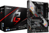
... notice. Because the motherboard specifications and the BIOS software might be updated, the content of this documentation occur, the updated version will be available on ASRock's website as well. ASRock website http://www.asrock.com. 1.1 Package Contents • ASRock Z390 Phantom Gaming 7 Motherboard (ATX Form Factor) • ASRock Z390 Phantom Gaming 7 Quick Installation Guide • ASRock Z390 Phantom Gaming 7 Support CD • 4 x Serial ATA (SATA) Data...
... notice. Because the motherboard specifications and the BIOS software might be updated, the content of this documentation occur, the updated version will be available on ASRock's website as well. ASRock website http://www.asrock.com. 1.1 Package Contents • ASRock Z390 Phantom Gaming 7 Motherboard (ATX Form Factor) • ASRock Z390 Phantom Gaming 7 Quick Installation Guide • ASRock Z390 Phantom Gaming 7 Support CD • 4 x Serial ATA (SATA) Data...

Quick Installation Guide
Page 12
... Gen1 Headers (Support 4 USB 3.2 Gen1 ports) (ASMedia ASM1074 hub) (Supports ESD Protection) • 1 x Front Panel Type C USB 3.2 Gen1 Header (Intel® Z390) (Supports ESD Protection) • 1 x Performance Mode / Easy OC Header • 1 x Dr. Debug with LED • 1 x Power Button with LED •...; 1 x Reset Button with LED • 2 x AMI UEFI Legal BIOS with multilingual GUI support (1 x Main BIOS and 1 x Backup BIOS) • Supports Secure Backup UEFI Technology • ACPI 6.0 Compliant wake up events • SMBIOS 2.7 Support • CPU...
... Gen1 Headers (Support 4 USB 3.2 Gen1 ports) (ASMedia ASM1074 hub) (Supports ESD Protection) • 1 x Front Panel Type C USB 3.2 Gen1 Header (Intel® Z390) (Supports ESD Protection) • 1 x Performance Mode / Easy OC Header • 1 x Dr. Debug with LED • 1 x Power Button with LED •...; 1 x Reset Button with LED • 2 x AMI UEFI Legal BIOS with multilingual GUI support (1 x Main BIOS and 1 x Backup BIOS) • Supports Secure Backup UEFI Technology • ACPI 6.0 Compliant wake up events • SMBIOS 2.7 Support • CPU...
Quick Installation Guide
Page 13
English 11 Z390 Phantom Gaming 7 Hardware Monitor OS Certifications • Temperature Sensing: CPU, CPU/Water Pump, Chassis/ Water Pump Fans • Fan Tachometer: CPU, CPU/Water Pump, Chassis/Water Pump .../EuP ready power supply is required) * For detailed product information, please visit our website: http://www.asrock.com Please realize that there is a certain risk involved with overclocking, including adjusting the setting in the BIOS, applying Untied Overclocking Technology, or using third-party overclocking tools. Overclocking may affect your system's stability, or...
English 11 Z390 Phantom Gaming 7 Hardware Monitor OS Certifications • Temperature Sensing: CPU, CPU/Water Pump, Chassis/ Water Pump Fans • Fan Tachometer: CPU, CPU/Water Pump, Chassis/Water Pump .../EuP ready power supply is required) * For detailed product information, please visit our website: http://www.asrock.com Please realize that there is a certain risk involved with overclocking, including adjusting the setting in the BIOS, applying Untied Overclocking Technology, or using third-party overclocking tools. Overclocking may affect your system's stability, or...

Quick Installation Guide
Page 22
... cap to short the pins on the pins, the jumper is "Open". If you need to clear the CMOS when you just finish updating the BIOS, you must boot up the system first, and then shut it down before you to remove the jumper cap after clearing the CMOS. 2.5 Jumpers Setup...
... cap to short the pins on the pins, the jumper is "Open". If you need to clear the CMOS when you just finish updating the BIOS, you must boot up the system first, and then shut it down before you to remove the jumper cap after clearing the CMOS. 2.5 Jumpers Setup...

Quick Installation Guide
Page 155
Z390 Phantom Gaming 7 OS 인증 • Microsoft® Windows® 10 64- 비트 • FCC, CE • ErP/EuP ErP/EuP http://www.asrock.com BIOS Untied Overclocking Technology 한국어 153
Z390 Phantom Gaming 7 OS 인증 • Microsoft® Windows® 10 64- 비트 • FCC, CE • ErP/EuP ErP/EuP http://www.asrock.com BIOS Untied Overclocking Technology 한국어 153

User Manual
Page 5
... and M2_2) 43 Chapter 3 Software and Utilities Operation 47 3.1 Installing Drivers 47 3.2 Phantom Gaming Tuning 48 3.2.1 Installing Phantom Gaming Tuning 48 3.2.2 Using Phantom Gaming Tuning 48 3.3 ASRock Live Update & APP Shop 51 3.3.1 UI Overview 51 3.3.2 Apps 52 3.3.3 BIOS & Drivers 55 3.3.4 Setting 56 3.4 Creative SoundBlaster Cinema5 57 3.5 ASRock Polychrome SYNC 58 Chapter 4 UEFI SETUP UTILITY 61 4.1 Introduction 61 4.2 EZ Mode...
... and M2_2) 43 Chapter 3 Software and Utilities Operation 47 3.1 Installing Drivers 47 3.2 Phantom Gaming Tuning 48 3.2.1 Installing Phantom Gaming Tuning 48 3.2.2 Using Phantom Gaming Tuning 48 3.3 ASRock Live Update & APP Shop 51 3.3.1 UI Overview 51 3.3.2 Apps 52 3.3.3 BIOS & Drivers 55 3.3.4 Setting 56 3.4 Creative SoundBlaster Cinema5 57 3.5 ASRock Polychrome SYNC 58 Chapter 4 UEFI SETUP UTILITY 61 4.1 Introduction 61 4.2 EZ Mode...
User Manual
Page 7
Chapter 3 contains the operation guide of the BIOS setup. If you require technical support related to this documentation occur, the updated version will be available on ASRock's website as well. ASRock website http://www.asrock.com. 1.1 Package Contents • ASRock Z390 Phantom Gaming 7 Motherboard (ATX Form Factor) • ASRock Z390 Phantom Gaming 7 Quick Installation Guide • ASRock Z390 Phantom Gaming 7 Support CD • 4 x Serial ATA (SATA) Data...
Chapter 3 contains the operation guide of the BIOS setup. If you require technical support related to this documentation occur, the updated version will be available on ASRock's website as well. ASRock website http://www.asrock.com. 1.1 Package Contents • ASRock Z390 Phantom Gaming 7 Motherboard (ATX Form Factor) • ASRock Z390 Phantom Gaming 7 Quick Installation Guide • ASRock Z390 Phantom Gaming 7 Support CD • 4 x Serial ATA (SATA) Data...

User Manual
Page 12
...(15μ Gold Audio Connec- tor) • 1 x Thunderbolt AIC Connector (5-pin) • 2 x USB 2.0 Headers (Support 4 USB 2.0 ports) (Intel® Z390) (Supports ESD Protection) • 2 x USB 3.2 Gen1 Headers (Support 4 USB 3.2 Gen1 ports) (ASMedia ASM1074 hub) (Supports ESD Protection) • 1 x Front ...• 1 x Power Button with LED • 1 x Reset Button with LED • 2 x AMI UEFI Legal BIOS with multilingual GUI support (1 x Main BIOS and 1 x Backup BIOS) • Supports Secure Backup UEFI Technology • ACPI 6.0 Compliant wake up events • SMBIOS 2.7 Support • ...
...(15μ Gold Audio Connec- tor) • 1 x Thunderbolt AIC Connector (5-pin) • 2 x USB 2.0 Headers (Support 4 USB 2.0 ports) (Intel® Z390) (Supports ESD Protection) • 2 x USB 3.2 Gen1 Headers (Support 4 USB 3.2 Gen1 ports) (ASMedia ASM1074 hub) (Supports ESD Protection) • 1 x Front ...• 1 x Power Button with LED • 1 x Reset Button with LED • 2 x AMI UEFI Legal BIOS with multilingual GUI support (1 x Main BIOS and 1 x Backup BIOS) • Supports Secure Backup UEFI Technology • ACPI 6.0 Compliant wake up events • SMBIOS 2.7 Support • ...

User Manual
Page 13
Overclocking may affect your system's stability, or even cause damage to the components and devices of your own risk and expense. Z390 Phantom Gaming 7 Hardware Monitor OS Certifications • Temperature Sensing: CPU, CPU/Water Pump, Chassis/ Water Pump Fans • Fan Tachometer: CPU, CPU/Water Pump, Chassis/...8226; FCC, CE • ErP/EuP ready (ErP/EuP ready power supply is required) * For detailed product information, please visit our website: http://www.asrock.com Please realize that there is a certain risk involved with overclocking, including adjusting the setting in the...
Overclocking may affect your system's stability, or even cause damage to the components and devices of your own risk and expense. Z390 Phantom Gaming 7 Hardware Monitor OS Certifications • Temperature Sensing: CPU, CPU/Water Pump, Chassis/ Water Pump Fans • Fan Tachometer: CPU, CPU/Water Pump, Chassis/...8226; FCC, CE • ErP/EuP ready (ErP/EuP ready power supply is required) * For detailed product information, please visit our website: http://www.asrock.com Please realize that there is a certain risk involved with overclocking, including adjusting the setting in the...

User Manual
Page 14
...9 USB 3.2 Gen2 T: USB31_TA_1 Top: B: USB31_TC_1 RJ-45 10 USB3_5_6 Top: Central/Bass LINE IN Center: REAR SPK Bottom: Optical SPDIF Z390 Phantom Gaming 7 Top: Center: FRONT Bottom: MIC IN M2_1 31 LAN LAN CHA_FAN1/WP CT4 CT3 CT2 CT1 PCIE1 SATA3_4_5 1 1 USB31_TC_2 USB3_7_8 11 ...RGB_LED1 ADDR_LED1 1 1 PCIE6 RGB_LED2 1 1 T B1 CHA_FAN2/WP Ultra M.2 PCIe Gen3 x4 USB_1_2 1 USB_3_4 1 Dr. Debug BIOS_B_LED1 BIOS_B1 BIOS BIOS_A_LED1 BIOS_A1 BIOS SPI_TPM_J1 PM_OC 1 SPK_PLED1 PLED PWRBTN CHA_FAN3/WP 1 1 1 HDLED RESET PANEL1 29 28 27 26 25 24 23 22 21 20 19 ...
...9 USB 3.2 Gen2 T: USB31_TA_1 Top: B: USB31_TC_1 RJ-45 10 USB3_5_6 Top: Central/Bass LINE IN Center: REAR SPK Bottom: Optical SPDIF Z390 Phantom Gaming 7 Top: Center: FRONT Bottom: MIC IN M2_1 31 LAN LAN CHA_FAN1/WP CT4 CT3 CT2 CT1 PCIE1 SATA3_4_5 1 1 USB31_TC_2 USB3_7_8 11 ...RGB_LED1 ADDR_LED1 1 1 PCIE6 RGB_LED2 1 1 T B1 CHA_FAN2/WP Ultra M.2 PCIe Gen3 x4 USB_1_2 1 USB_3_4 1 Dr. Debug BIOS_B_LED1 BIOS_B1 BIOS BIOS_A_LED1 BIOS_A1 BIOS SPI_TPM_J1 PM_OC 1 SPK_PLED1 PLED PWRBTN CHA_FAN3/WP 1 1 1 HDLED RESET PANEL1 29 28 27 26 25 24 23 22 21 20 19 ...

User Manual
Page 26
... setup, please turn off the computer and unplug the power cord, then use a jumper cap to clear the CMOS when you just finish updating the BIOS, you must boot up the system first, and then shut it down before you do the clear-CMOS action. If you to remove the jumper...
... setup, please turn off the computer and unplug the power cord, then use a jumper cap to clear the CMOS when you just finish updating the BIOS, you must boot up the system first, and then shut it down before you do the clear-CMOS action. If you to remove the jumper...


