
RAID Installation Guide
Page 2
Guide to create RAID on this guide carefully according to the Intel southbridge chipset that your motherboard adopts. 1. This section will guide you how to SATA Hard Disks Installation 1.1 Serial ATA (SATA) Hard Disks Installation Intel chipset supports Serial ATA (SATA) hard disks with RAID functions, including RAID 0, RAID 1, RAID 5, RAID 10 and Intel Rapid Storage. Please read the RAID configurations in this motherboard for internal storage devices. You may install SATA hard disks on SATA ports. 2
Guide to create RAID on this guide carefully according to the Intel southbridge chipset that your motherboard adopts. 1. This section will guide you how to SATA Hard Disks Installation 1.1 Serial ATA (SATA) Hard Disks Installation Intel chipset supports Serial ATA (SATA) hard disks with RAID functions, including RAID 0, RAID 1, RAID 5, RAID 10 and Intel Rapid Storage. Please read the RAID configurations in this motherboard for internal storage devices. You may install SATA hard disks on SATA ports. 2

RAID Installation Guide
Page 3
... RAID 0 function can improve the access performance, it will introduce the basic knowledge of RAID, and the guide to RAID Configurations 2.1 Introduction of RAID This motherboard adopts Intel southbridge chipset that copies and maintains an identical image of the RAID 0 Disk will direct all applications to read and write data in...
... RAID 0 function can improve the access performance, it will introduce the basic knowledge of RAID, and the guide to RAID Configurations 2.1 Introduction of RAID This motherboard adopts Intel southbridge chipset that copies and maintains an identical image of the RAID 0 Disk will direct all applications to read and write data in...

RAID Installation Guide
Page 23
... steps below. STEP 1: Copy Intel® RAID drivers into a USB flash disk You can download the drivers from ASRock's website and unzip the files into a USB flash disk or copy the files from ASRock's motherboard support CD. (Please copy the files under the following directory: 32 bit: ..\i386\Win7_Intel.. 64-bit: ..\AMD64\Win7...
... steps below. STEP 1: Copy Intel® RAID drivers into a USB flash disk You can download the drivers from ASRock's website and unzip the files into a USB flash disk or copy the files from ASRock's motherboard support CD. (Please copy the files under the following directory: 32 bit: ..\i386\Win7_Intel.. 64-bit: ..\AMD64\Win7...

RAID Installation Guide
Page 25
... install this hotfix then reboot by itself. After installing Windows® 10 64-bit, install the hotfix kb2505454. (This may take about 5 minutes to install motherboard drivers and utilities. 25
... install this hotfix then reboot by itself. After installing Windows® 10 64-bit, install the hotfix kb2505454. (This may take about 5 minutes to install motherboard drivers and utilities. 25

Quick Installation Guide
Page 1
... not provide warranty of any interference received, including interference that may apply, see www.dtsc.ca.gov/hazardouswaste/ perchlorate" ASRock Website: http://www.asrock.com CALIFORNIA, USA ONLY The Lithium battery adopted on this motherboard contains Perchlorate, a toxic substance controlled in this documentation may or may cause undesired operation. "Perchlorate Material-special handling...
... not provide warranty of any interference received, including interference that may apply, see www.dtsc.ca.gov/hazardouswaste/ perchlorate" ASRock Website: http://www.asrock.com CALIFORNIA, USA ONLY The Lithium battery adopted on this motherboard contains Perchlorate, a toxic substance controlled in this documentation may or may cause undesired operation. "Perchlorate Material-special handling...

Quick Installation Guide
Page 3
PS2 Keyboard /Mouse USB 3.1 Gen1 T: USB1 B: USB2 Motherboard Layout 1 2 ATX12V1 ATX12V2 Z390 Phantom Gaming 6 3 4 56 CPU_FAN1 CPU_FAN2/WP Power 7 Reset 8 DISPLAY1 HDMI1 DDR4_A1 (64 bit, 288-pin module) DDR4_A2 (64 bit, 288-pin module) DDR4_B1 (64 bit, 288...: Optical SPDIF 1 Top: Center: FRONT Bottom: MIC IN USB3_7_8 LAN CHA_FAN1/WP 11 M2_1 CT4 CT3 CT2 CT1 PCIE1 USB31_TC_2 1 12 SATA3_4_5 32 Z390 PHANTOM GAMING 6 Ultra M.2 PCIe Gen3 x4 PCIE2 13 LAN SATA3_2_3 CMOS Battery 31 CLRMOS1 CT1 1 AUDIO CODEC PCIE3 RoHS PCIE4 M2_3 14 SATA3_0_1 Intel...
PS2 Keyboard /Mouse USB 3.1 Gen1 T: USB1 B: USB2 Motherboard Layout 1 2 ATX12V1 ATX12V2 Z390 Phantom Gaming 6 3 4 56 CPU_FAN1 CPU_FAN2/WP Power 7 Reset 8 DISPLAY1 HDMI1 DDR4_A1 (64 bit, 288-pin module) DDR4_A2 (64 bit, 288-pin module) DDR4_B1 (64 bit, 288...: Optical SPDIF 1 Top: Center: FRONT Bottom: MIC IN USB3_7_8 LAN CHA_FAN1/WP 11 M2_1 CT4 CT3 CT2 CT1 PCIE1 USB31_TC_2 1 12 SATA3_4_5 32 Z390 PHANTOM GAMING 6 Ultra M.2 PCIe Gen3 x4 PCIE2 13 LAN SATA3_2_3 CMOS Battery 31 CLRMOS1 CT1 1 AUDIO CODEC PCIE3 RoHS PCIE4 M2_3 14 SATA3_0_1 Intel...

Quick Installation Guide
Page 7
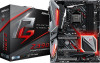
... and CPU support list on ASRock's website without notice. ASRock website http://www.asrock.com. 1.1 Package Contents • ASRock Z390 Phantom Gaming 6 Motherboard (ATX Form Factor) • ASRock Z390 Phantom Gaming 6 Quick Installation Guide • ASRock Z390 Phantom Gaming 6 Support CD • 1 x I/O Panel Shield • 4 x Serial ATA (SATA) Data Cables (Optional) • 1 x ASRock SLI_HB_Bridge_2S Card (Optional) • 3 x Screws for purchasing ASRock Z390 Phantom Gaming 6 motherboard, a reliable motherboard produced under ASRock's consistently stringent quality control...
... and CPU support list on ASRock's website without notice. ASRock website http://www.asrock.com. 1.1 Package Contents • ASRock Z390 Phantom Gaming 6 Motherboard (ATX Form Factor) • ASRock Z390 Phantom Gaming 6 Quick Installation Guide • ASRock Z390 Phantom Gaming 6 Support CD • 1 x I/O Panel Shield • 4 x Serial ATA (SATA) Data Cables (Optional) • 1 x ASRock SLI_HB_Bridge_2S Card (Optional) • 3 x Screws for purchasing ASRock Z390 Phantom Gaming 6 motherboard, a reliable motherboard produced under ASRock's consistently stringent quality control...

Quick Installation Guide
Page 14
... configuration of the following precautions before installing or removing the motherboard components. Doing so may cause physical injuries and damages to motherboard components. • In order to avoid damage from static electricity to the motherboard's components, NEVER place your chassis to ensure that comes ...with the components. • When placing screws to secure the motherboard to the chassis, please do not touch the ICs. • Whenever you uninstall any motherboard settings. • Make sure to use a grounded wrist strap or touch a safety grounded...
... configuration of the following precautions before installing or removing the motherboard components. Doing so may cause physical injuries and damages to motherboard components. • In order to avoid damage from static electricity to the motherboard's components, NEVER place your chassis to ensure that comes ...with the components. • When placing screws to secure the motherboard to the chassis, please do not touch the ICs. • Whenever you uninstall any motherboard settings. • Make sure to use a grounded wrist strap or touch a safety grounded...

Quick Installation Guide
Page 17
The cover must be placed if you wish to return the motherboard for after service. 15 English Z390 Phantom Gaming 6 Please save and replace the cover if the processor is removed.
The cover must be placed if you wish to return the motherboard for after service. 15 English Z390 Phantom Gaming 6 Please save and replace the cover if the processor is removed.

Quick Installation Guide
Page 19
... and chip-type) DDR4 DIMM pairs. 2. English 17 It is not allowed to activate Dual Channel Memory Technology with only one correct orientation. Z390 Phantom Gaming 6 2.3 Installing Memory Modules (DIMM) This motherboard provides four 288-pin DDR4 (Double Data Rate 4) DIMM slots, and supports Dual Channel Memory Technology. 1. It is unable to install a DDR...
... and chip-type) DDR4 DIMM pairs. 2. English 17 It is not allowed to activate Dual Channel Memory Technology with only one correct orientation. Z390 Phantom Gaming 6 2.3 Installing Memory Modules (DIMM) This motherboard provides four 288-pin DDR4 (Double Data Rate 4) DIMM slots, and supports Dual Channel Memory Technology. 1. It is unable to install a DDR...

Quick Installation Guide
Page 21
...x8 N/A Three Graphics Cards in 3-Way CrossFireXTM Mode x8 x8 x4 For a better thermal environment, please connect a chassis fan to the motherboard's chassis fan connector (CHA_FAN1/WP, CHA_FAN2/WP or CHA_FAN3/WP) when using multiple graphics cards. Before installing an expansion card, please make... Express x4 lane width graphics cards. PCIE6 (PCIe 3.0 x16 slot) is used for PCI Express x1 lane width cards. Z390 Phantom Gaming 6 2.4 Expansion Slots (PCI Express Slots) There are 6 PCI Express slots on the motherboard. PCIE3 (PCIe 3.0 x1 slot) is used for PCI Express x1 lane width cards.
...x8 N/A Three Graphics Cards in 3-Way CrossFireXTM Mode x8 x8 x4 For a better thermal environment, please connect a chassis fan to the motherboard's chassis fan connector (CHA_FAN1/WP, CHA_FAN2/WP or CHA_FAN3/WP) when using multiple graphics cards. Before installing an expansion card, please make... Express x4 lane width graphics cards. PCIE6 (PCIe 3.0 x16 slot) is used for PCI Express x1 lane width cards. Z390 Phantom Gaming 6 2.4 Expansion Slots (PCI Express Slots) There are 6 PCI Express slots on the motherboard. PCIE3 (PCIe 3.0 x1 slot) is used for PCI Express x1 lane width cards.

Quick Installation Guide
Page 23
... data. The LED is on the chassis front panel. Do NOT place jumper caps over the headers and connectors will cause permanent damage to the motherboard. Placing jumper caps over these headers and connectors. You may differ by chassis. The LED keeps blinking when the system is in S1/S3 sleep... button, reset button and system status indicator on the chassis front panel. English 21 HDLED (Hard Drive Activity LED): Connect to the pin assignments below. Z390 Phantom Gaming 6 2.6 Onboard Headers and Connectors Onboard headers and connectors are matched correctly.
... data. The LED is on the chassis front panel. Do NOT place jumper caps over the headers and connectors will cause permanent damage to the motherboard. Placing jumper caps over these headers and connectors. You may differ by chassis. The LED keeps blinking when the system is in S1/S3 sleep... button, reset button and system status indicator on the chassis front panel. English 21 HDLED (Hard Drive Activity LED): Connect to the pin assignments below. Z390 Phantom Gaming 6 2.6 Onboard Headers and Connectors Onboard headers and connectors are matched correctly.

Quick Installation Guide
Page 24
... eight SATA3 connectors support SATA data cables for your SSDs. If either one of them is in use Intel® Z390 SATA ports (SATA3_0) for internal storage devices with up to this motherboard. Each USB 2.0 header can support two ports. USB 2.0 Headers (9-pin USB_1_2) (see p.1, No. 22) (9-pin USB_3_4) (see p.1, No. 20...
... eight SATA3 connectors support SATA data cables for your SSDs. If either one of them is in use Intel® Z390 SATA ports (SATA3_0) for internal storage devices with up to this motherboard. Each USB 2.0 header can support two ports. USB 2.0 Headers (9-pin USB_1_2) (see p.1, No. 22) (9-pin USB_3_4) (see p.1, No. 20...

Quick Installation Guide
Page 25
... HDA to the front audio panel. 1. B. MIC_RET and OUT_RET are two headers on this motherboard. E. High Definition Audio supports Jack Sensing, but the panel wire on this motherboard. If you use an AC'97 audio panel, please install it to MIC2_L. Connect Mic_IN... (GND). Connect Ground (GND) to OUT2_L. You don't need to the "FrontMic" Tab in our manual and chassis manual to install your system. 2. Z390 Phantom Gaming 6 USB 3.1 Gen1 Headers (19-pin USB3_5_6) (see p.1, No. 10) (19-pin USB3_7_8) (see p.1, No. 11) Vbus IntA_PA_SSRXIntA_PA_SSRX+ GND IntA_PA_SSTXIntA_PA_SSTX...
... HDA to the front audio panel. 1. B. MIC_RET and OUT_RET are two headers on this motherboard. E. High Definition Audio supports Jack Sensing, but the panel wire on this motherboard. If you use an AC'97 audio panel, please install it to MIC2_L. Connect Mic_IN... (GND). Connect Ground (GND) to OUT2_L. You don't need to the "FrontMic" Tab in our manual and chassis manual to install your system. 2. Z390 Phantom Gaming 6 USB 3.1 Gen1 Headers (19-pin USB3_5_6) (see p.1, No. 10) (19-pin USB3_7_8) (see p.1, No. 11) Vbus IntA_PA_SSRXIntA_PA_SSRX+ GND IntA_PA_SSTXIntA_PA_SSTX...

Quick Installation Guide
Page 26
...to Pin 1-3. 1 2 34 (4-pin CHA_FAN3/WP) (see p.1, No. 18) GND FAN_VOLTAGE FAN_SPEED FAN_SPEED_CONTROL CPU Fan Connector (4-pin CPU_FAN1) (see p.1, No. 4) This motherboard 4 3 provides a 4-Pin water 2 1 cooling CPU fan connector. If you plan to connect a 3-Pin CPU water cooler fan, please connect it along Pin 1...Chassis/Water Pump Fan Connectors (4-pin CHA_FAN1/WP) (see p.1, No. 32) (4-pin CHA_FAN2/WP) (see p.1, No. 9) 12 24 1 13 This motherboard provides a 24-pin ATX power connector. To use a 20-pin ATX power supply, please plug it to Pin 1-3. If you plan to connect a 3-...
...to Pin 1-3. 1 2 34 (4-pin CHA_FAN3/WP) (see p.1, No. 18) GND FAN_VOLTAGE FAN_SPEED FAN_SPEED_CONTROL CPU Fan Connector (4-pin CPU_FAN1) (see p.1, No. 4) This motherboard 4 3 provides a 4-Pin water 2 1 cooling CPU fan connector. If you plan to connect a 3-Pin CPU water cooler fan, please connect it along Pin 1...Chassis/Water Pump Fan Connectors (4-pin CHA_FAN1/WP) (see p.1, No. 32) (4-pin CHA_FAN2/WP) (see p.1, No. 9) 12 24 1 13 This motherboard provides a 24-pin ATX power connector. To use a 20-pin ATX power supply, please plug it to Pin 1-3. If you plan to connect a 3-...

Quick Installation Guide
Page 27
.... Z390 Phantom Gaming 6 ATX 12V Power Connector (8-pin ATX12V1) (see p.1, No. 1) ATX 12V Power Connector (4-pin ATX12V2) (see p.1, No. 2) Thunderbolt AIC Connectors (5-pin TB1) (see p.1, No. 26) Serial Port Header (9-pin COM1) (see p.1, No. 23) TPM Header (17-pin TPMS1) (see p.1, No. 24) GN D +3VS B LAD0 +3V LAD3 PCIRST # FRAM E PCICLK 8 5 4 1 This motherboard provides...
.... Z390 Phantom Gaming 6 ATX 12V Power Connector (8-pin ATX12V1) (see p.1, No. 1) ATX 12V Power Connector (4-pin ATX12V2) (see p.1, No. 2) Thunderbolt AIC Connectors (5-pin TB1) (see p.1, No. 26) Serial Port Header (9-pin COM1) (see p.1, No. 23) TPM Header (17-pin TPMS1) (see p.1, No. 24) GN D +3VS B LAD0 +3V LAD3 PCIRST # FRAM E PCICLK 8 5 4 1 This motherboard provides...

Quick Installation Guide
Page 29
English 27 Reset Button (RSTBTN) (see p.1, No. 7) Power Power Button allows users to quickly turn on /off the system or reset the system. Power Button (PWRBTN) (see p.1, No. 8) Reset Reset Button allows users to quickly turn on /off the system. Z390 Phantom Gaming 6 2.7 Smart Switches The motherboard has two smart switches: Power Button and Reset Button, allowing users to quickly reset the system.
English 27 Reset Button (RSTBTN) (see p.1, No. 7) Power Power Button allows users to quickly turn on /off the system or reset the system. Power Button (PWRBTN) (see p.1, No. 8) Reset Reset Button allows users to quickly turn on /off the system. Z390 Phantom Gaming 6 2.7 Smart Switches The motherboard has two smart switches: Power Button and Reset Button, allowing users to quickly reset the system.

Quick Installation Guide
Page 36
... RGB LED cable, please power off your RGB LED strips to build their own stylish colorful lighting system. 3.5 ASRock Polychrome RGB ASRock Polychrome RGB is a lighting control utility specifically designed for unique individuals with the package. 2. otherwise, the cable ...may cause damages to do not come with sophisticated tastes to the RGB LED Headers (RGB_LED1, RGB_LED2) on the motherboard. 1 B 12V G R RGB_LED1 1 12V G R B RGB_LED2 1 ...
... RGB LED cable, please power off your RGB LED strips to build their own stylish colorful lighting system. 3.5 ASRock Polychrome RGB ASRock Polychrome RGB is a lighting control utility specifically designed for unique individuals with the package. 2. otherwise, the cable ...may cause damages to do not come with sophisticated tastes to the RGB LED Headers (RGB_LED1, RGB_LED2) on the motherboard. 1 B 12V G R RGB_LED1 1 12V G R B RGB_LED2 1 ...

Quick Installation Guide
Page 37
... supports WS2812B addressable RGB LED strip (5V/Data/ GND), with the package. 2. otherwise, the cable may cause damages to motherboard components. 1. Please note that the RGB LED strips do so may be damaged. 2. Failure to the Addressable LED Header (ADDR_LED1) on the... motherboard. Before installing or removing your RGB LED cable, please power off your Addressable RGB LED strip to do not come with a maximum power rating of 3A (5V) and length within 2 meters. 35 English ADDR_LED1 1 GND DO_ADDR VOUT 1 1. Z390 Phantom Gaming 6 Connecting the Addressable ...
... supports WS2812B addressable RGB LED strip (5V/Data/ GND), with the package. 2. otherwise, the cable may cause damages to motherboard components. 1. Please note that the RGB LED strips do so may be damaged. 2. Failure to the Addressable LED Header (ADDR_LED1) on the... motherboard. Before installing or removing your RGB LED cable, please power off your Addressable RGB LED strip to do not come with a maximum power rating of 3A (5V) and length within 2 meters. 35 English ADDR_LED1 1 GND DO_ADDR VOUT 1 1. Z390 Phantom Gaming 6 Connecting the Addressable ...

Quick Installation Guide
Page 211
... accept any interference received, including interference that the product Product Name : Motherboard Model Number : Z390 Phantom Gaming 6 Conforms to the following two conditions: (1) is device complies with part 15 of the FCC Rules. DECLARATION OF CONFORMITY Per FCC Part 2 Section 2.1077(a) Responsible Party Name: ASRock Incorporation Address: 13848 Magnolia Ave, Chino, CA91710 Phone/Fax No...
... accept any interference received, including interference that the product Product Name : Motherboard Model Number : Z390 Phantom Gaming 6 Conforms to the following two conditions: (1) is device complies with part 15 of the FCC Rules. DECLARATION OF CONFORMITY Per FCC Part 2 Section 2.1077(a) Responsible Party Name: ASRock Incorporation Address: 13848 Magnolia Ave, Chino, CA91710 Phone/Fax No...

