Quick Installation Guide
Page 4
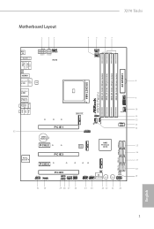
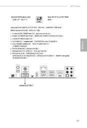
X570 Taichi Motherboard Layout 1 23 4 5 67 BIOS _FB1 M2_WIFI_1 ATX12V1 CHA_FAN3/WP ATX12V2 RoHS CPU_FAN1 CPU_FAN2/WP PS2 Keyboard /Mouse USB 3.2 Gen1 T: USB1 B: USB2 ATXPWR1 X570 Taichi DDR4_A1 (64 bit, 288-pin module) DDR4_A2 (64 bit, 288-pin module) ...FRONT Bottom: MIC IN USB_5 1 CHA_FAN1/WP AMD_FAN_LED1 M2_1 32 PCIE1 1 CHA_FAN4 /WP SPI_TPM_J1 1 F_USB31_TC_1 CMOS Battery PCIE2 AMD M2_2 BIOS ROM Premium X570 SATA3_1_2 SATA3_3_4 SATA3_5_6 Purity SoundTM 4 PCIE3 PCIE4 M2_3 SATA3_7_8 HD_AUDIO1 1 1 T B1 PCIE5 ADDR_LED1 1 CHA_FAN2/WP SPK_PLED1 RGB_HEADER1 1 1...
X570 Taichi Motherboard Layout 1 23 4 5 67 BIOS _FB1 M2_WIFI_1 ATX12V1 CHA_FAN3/WP ATX12V2 RoHS CPU_FAN1 CPU_FAN2/WP PS2 Keyboard /Mouse USB 3.2 Gen1 T: USB1 B: USB2 ATXPWR1 X570 Taichi DDR4_A1 (64 bit, 288-pin module) DDR4_A2 (64 bit, 288-pin module) ...FRONT Bottom: MIC IN USB_5 1 CHA_FAN1/WP AMD_FAN_LED1 M2_1 32 PCIE1 1 CHA_FAN4 /WP SPI_TPM_J1 1 F_USB31_TC_1 CMOS Battery PCIE2 AMD M2_2 BIOS ROM Premium X570 SATA3_1_2 SATA3_3_4 SATA3_5_6 Purity SoundTM 4 PCIE3 PCIE4 M2_3 SATA3_7_8 HD_AUDIO1 1 1 T B1 PCIE5 ADDR_LED1 1 CHA_FAN2/WP SPK_PLED1 RGB_HEADER1 1 1...
Quick Installation Guide
Page 9
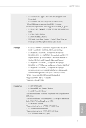
...) • ASRock X570 Taichi Quick Installation Guide • ASRock X570 Taichi Support CD • 4 x Serial ATA (SATA) Data Cables (Optional) • 1 x ASRock SLI_HB_Bridge_2S Card (Optional) • 2 x ASRock WiFi 2.4/5 GHz Antennas • 1 x ASRock Screwdriver (Optional) • 3 x Screws for M.2 Socket (Optional) • 2 x Standoffs for purchasing ASRock X570 Taichi motherboard, a reliable motherboard produced under ASRock's consistently stringent quality control. Because the motherboard specifications and the BIOS software...
...) • ASRock X570 Taichi Quick Installation Guide • ASRock X570 Taichi Support CD • 4 x Serial ATA (SATA) Data Cables (Optional) • 1 x ASRock SLI_HB_Bridge_2S Card (Optional) • 2 x ASRock WiFi 2.4/5 GHz Antennas • 1 x ASRock Screwdriver (Optional) • 3 x Screws for M.2 Socket (Optional) • 2 x Standoffs for purchasing ASRock X570 Taichi motherboard, a reliable motherboard produced under ASRock's consistently stringent quality control. Because the motherboard specifications and the BIOS software...

Quick Installation Guide
Page 13
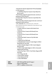
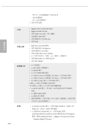
... is not supported on USB3_5_6ports. • 1 x RJ-45 LAN Port with LED (ACT/LINK LED and SPEED LED) • 1 x Clear CMOS Button • 1 x BIOS Flashback Button • HD Audio Jacks: Rear Speaker / Central / Bass / Line in / Front Speaker / Microphone (Gold Audio Jacks) Storage • 8 x SATA3 6.0 Gb/s... and M.2 PCI Express module up to Gen4x4 (64 Gb/s)* * If M2_3 is occupied, PCIE5 slot will be disabled * Supports NVMe SSD as boot disks * Supports ASRock U.2 Kit Connector • 1 x SPI TPM Header • 1 x Power LED and Speaker Header • 1 x AMD Fan LED Header * The AMD Fan...
... is not supported on USB3_5_6ports. • 1 x RJ-45 LAN Port with LED (ACT/LINK LED and SPEED LED) • 1 x Clear CMOS Button • 1 x BIOS Flashback Button • HD Audio Jacks: Rear Speaker / Central / Bass / Line in / Front Speaker / Microphone (Gold Audio Jacks) Storage • 8 x SATA3 6.0 Gb/s... and M.2 PCI Express module up to Gen4x4 (64 Gb/s)* * If M2_3 is occupied, PCIE5 slot will be disabled * Supports NVMe SSD as boot disks * Supports ASRock U.2 Kit Connector • 1 x SPI TPM Header • 1 x Power LED and Speaker Header • 1 x AMD Fan LED Header * The AMD Fan...
Quick Installation Guide
Page 14
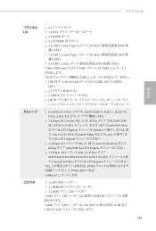
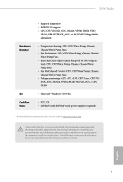
X570 Taichi BIOS Feature * The CPU Fan Connector supports the CPU fan of maximum 1A (12W) fan power. • 1 x CPU/Water Pump Fan Connector (4-pin) (Smart Fan Speed ...-Density Power Connector) • 1 x Front Panel Audio Connector (15μ Gold Audio Connector) • 1 x AMD LED Fan USB Header • 1 x Thunderbolt AIC Connector (5-pin) (Supports ASRock Thunderbolt AIC Card only) • 2 x USB 2.0 Headers (Support 4 USB 2.0 ports) (Supports ESD Protection) • 1 x USB 3.2 Gen1 Header (Supports 2 USB 3.2 Gen1 ports) (Supports ESD Protection) •...
X570 Taichi BIOS Feature * The CPU Fan Connector supports the CPU fan of maximum 1A (12W) fan power. • 1 x CPU/Water Pump Fan Connector (4-pin) (Smart Fan Speed ...-Density Power Connector) • 1 x Front Panel Audio Connector (15μ Gold Audio Connector) • 1 x AMD LED Fan USB Header • 1 x Thunderbolt AIC Connector (5-pin) (Supports ASRock Thunderbolt AIC Card only) • 2 x USB 2.0 Headers (Support 4 USB 2.0 ports) (Supports ESD Protection) • 1 x USB 3.2 Gen1 Header (Supports 2 USB 3.2 Gen1 ports) (Supports ESD Protection) •...

Quick Installation Guide
Page 15
.../EuP ready power supply is required) * For detailed product information, please visit our website: http://www.asrock.com Please realize that there is a certain risk involved with overclocking, including adjusting the setting in the BIOS, applying Untied Overclocking Technology, or using third-party overclocking tools. It should be done at your system...
.../EuP ready power supply is required) * For detailed product information, please visit our website: http://www.asrock.com Please realize that there is a certain risk involved with overclocking, including adjusting the setting in the BIOS, applying Untied Overclocking Technology, or using third-party overclocking tools. It should be done at your system...

Quick Installation Guide
Page 33
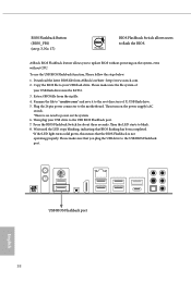
... setup, please turn off the computer and unplug the power cord, then use a jumper cap to clear the CMOS when you just finish updating the BIOS, you must boot up the system first, and then shut it down before you to remove the jumper cap after clearing the CMOS. English 30...
... setup, please turn off the computer and unplug the power cord, then use a jumper cap to clear the CMOS when you just finish updating the BIOS, you must boot up the system first, and then shut it down before you to remove the jumper cap after clearing the CMOS. English 30...
Quick Installation Guide
Page 41
... 38 Please make sure that the BIOS Flashback is no need to the root directory of your USB flash drive must be FAT32. 3. Rename the file to "creative.rom" and save it to power on the system, even without CPU. ASRock BIOS Flashback feature allows you plug the... USB drive to blink. 8. To use the USB BIOS Flashback function, Please follow the steps below. 1. Extract BIOS file from ASRock's website : http://www.asrock.com. 2. Then turn on the power supply's AC switch....
... 38 Please make sure that the BIOS Flashback is no need to the root directory of your USB flash drive must be FAT32. 3. Rename the file to "creative.rom" and save it to power on the system, even without CPU. ASRock BIOS Flashback feature allows you plug the... USB drive to blink. 8. To use the USB BIOS Flashback function, Please follow the steps below. 1. Extract BIOS file from ASRock's website : http://www.asrock.com. 2. Then turn on the power supply's AC switch....
Quick Installation Guide
Page 176
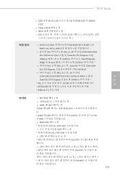
X570 Taichi 한국어 • LED 장착 RJ-45 LAN 포트 1 개 (ACT/LINK LED 및 SPEED LED) • Clear CMOS 버튼 1 개 • BIOS 1 개 • HD • SATA3 6.0 Gb/s 커넥터 8 개가 RAID(RAID .../2260/2280/22110 M.2 SATA3 6.0Gb/s 모듈 및 Gen4 M.2 PCI Express 모듈 4 개 (64Gb/s * M2_3 PCIE5 NVMe SSD ASRock U.2 커넥터 • SPI TPM 헤더 1 LED 1 개 • AMD 팬 LED 헤더 1 개 ...
X570 Taichi 한국어 • LED 장착 RJ-45 LAN 포트 1 개 (ACT/LINK LED 및 SPEED LED) • Clear CMOS 버튼 1 개 • BIOS 1 개 • HD • SATA3 6.0 Gb/s 커넥터 8 개가 RAID(RAID .../2260/2280/22110 M.2 SATA3 6.0Gb/s 모듈 및 Gen4 M.2 PCI Express 모듈 4 개 (64Gb/s * M2_3 PCIE5 NVMe SSD ASRock U.2 커넥터 • SPI TPM 헤더 1 LED 1 개 • AMD 팬 LED 헤더 1 개 ...
Quick Installation Guide
Page 178
한국어 X570 Taichi http://www.asrock.com BIOS Untied Overclocking Technology 175
한국어 X570 Taichi http://www.asrock.com BIOS Untied Overclocking Technology 175

Quick Installation Guide
Page 187
BIOS 4 creative.rom X: USB 5. 24 AC 6. 이제 USB USB BIOS 7. BIOS 파일을 USB USB FAT32 3. BIOS BIOS_FB1) (3 17 BIOS BIOS ASRock BIOS CPU BIOS USB BIOS 1. BIOS 3 LED 8. ASRock BIOS http://www.asrock.com. 2. LED BIOS *LED BIOS USB USB BIOS 한 국 어 USB BIOS 184
BIOS 4 creative.rom X: USB 5. 24 AC 6. 이제 USB USB BIOS 7. BIOS 파일을 USB USB FAT32 3. BIOS BIOS_FB1) (3 17 BIOS BIOS ASRock BIOS CPU BIOS USB BIOS 1. BIOS 3 LED 8. ASRock BIOS http://www.asrock.com. 2. LED BIOS *LED BIOS USB USB BIOS 한 국 어 USB BIOS 184
Quick Installation Guide
Page 192
X570 Taichi 日本語 ϦΞύωϧ I/O ετϨʔδ ίωΫλ &#...674;ACT/LINK LED ͱ SPEED LEDʣ • 1 x ΫϦΞ CMOS Ϙλϯ • 1 x BIOS HD • 8 x SATA3 6.0 Gb/s ίωΫλɺRAIDʢRAID 0ɺRAID 1ɺRAID 10ʣɺ NCQ&#... SATA3 6.0 Gb/s Gen4 x4 (64 Gb/s) ·Ͱͷ M.2 PCI Express * M2_3 PCIE5 NVMe SSD ʹରԠ * ASRock U.2 • 1 x SPI TPM 1 x LED 1 x AMD ϑΝϯ LED ϔομʔ * AMD &#...
X570 Taichi 日本語 ϦΞύωϧ I/O ετϨʔδ ίωΫλ &#...674;ACT/LINK LED ͱ SPEED LEDʣ • 1 x ΫϦΞ CMOS Ϙλϯ • 1 x BIOS HD • 8 x SATA3 6.0 Gb/s ίωΫλɺRAIDʢRAID 0ɺRAID 1ɺRAID 10ʣɺ NCQ&#... SATA3 6.0 Gb/s Gen4 x4 (64 Gb/s) ·Ͱͷ M.2 PCI Express * M2_3 PCIE5 NVMe SSD ʹରԠ * ASRock U.2 • 1 x SPI TPM 1 x LED 1 x AMD ϑΝϯ LED ϔομʔ * AMD &#...
Quick Installation Guide
Page 207
... 保护 ) * USB3_5_6 USB USB3_5_6 ACPI 1 x RJ-45 LAN LED(ACT/LINK LED 和 SPEED LED) • 1 x 清除 CMOS 按钮 • 1 x BIOS 存储 204 • 8 x SATA3 6.0 Gb/s RAID (RAID 0、RAID 1 和 RAID 10)、NCQ、AHCI • 1 x 超级 M.2 Socket (M2_1),支持...
... 保护 ) * USB3_5_6 USB USB3_5_6 ACPI 1 x RJ-45 LAN LED(ACT/LINK LED 和 SPEED LED) • 1 x 清除 CMOS 按钮 • 1 x BIOS 存储 204 • 8 x SATA3 6.0 Gb/s RAID (RAID 0、RAID 1 和 RAID 10)、NCQ、AHCI • 1 x 超级 M.2 Socket (M2_1),支持...
Quick Installation Guide
Page 218
簡体中文 X570 Taichi BIOS BIOS_FB1) (见第 3 页,第 17 个) BIOS BIOS。 ASRock BIOS CPU BIOS。 要使用 USB BIOS 1. 从 ASRock BIOS 文件:http://www.asrock.com。 2. 将 BIOS USB USB FAT32。 3 BIOS 文件。 4 creative.rom X: USB 5. 将 24 6. 然后将 USB USB BIOS 7. 按住 BIOS LED 8. 等待 LED BIOS * 如果 LED BIOS USB USB BIOS USB BIOS 215
簡体中文 X570 Taichi BIOS BIOS_FB1) (见第 3 页,第 17 个) BIOS BIOS。 ASRock BIOS CPU BIOS。 要使用 USB BIOS 1. 从 ASRock BIOS 文件:http://www.asrock.com。 2. 将 BIOS USB USB FAT32。 3 BIOS 文件。 4 creative.rom X: USB 5. 将 24 6. 然后将 USB USB BIOS 7. 按住 BIOS LED 8. 等待 LED BIOS * 如果 LED BIOS USB USB BIOS USB BIOS 215

Quick Installation Guide
Page 235
...;鈕 (BIOS_FB1 3 17) BIOS Flashback BIOS。 ASRock BIOS Flashback CPU BIOS。 USB BIOS Flashback 1. 從 ASRock BIOS 檔案:http://www.asrock.com。 2. 將 BIOS USB USB FAT32。 3. 從 zip BIOS 檔案。 4 creative.rom X: USB 5. 將 24 pin AC 開關。 6. 接著將 USB USB BIOS Flashback 7. 按住 BIOS Flashback LED 8. 等...
...;鈕 (BIOS_FB1 3 17) BIOS Flashback BIOS。 ASRock BIOS Flashback CPU BIOS。 USB BIOS Flashback 1. 從 ASRock BIOS 檔案:http://www.asrock.com。 2. 將 BIOS USB USB FAT32。 3. 從 zip BIOS 檔案。 4 creative.rom X: USB 5. 將 24 pin AC 開關。 6. 接著將 USB USB BIOS Flashback 7. 按住 BIOS Flashback LED 8. 等...

User Manual
Page 6
...) 58 Chapter 3 Software and Utilities Operation 61 3.1 Installing Drivers 61 3.2 A-Tuning 62 3.2.1 Installing A-Tuning 62 3.2.2 Using A-Tuning 62 3.3 ASRock Live Update & APP Shop 65 3.3.1 UI Overview 65 3.3.2 Apps 66 3.3.3 BIOS & Drivers 69 3.3.4 Setting 70 3.4 ASRock Polychrome SYNC 71 Chapter 4 UEFI SETUP UTILITY 74 4.1 Introduction 74 4.1.1 UEFI Menu Bar 74 4.1.2 Navigation Keys 75 4.2 Main...
...) 58 Chapter 3 Software and Utilities Operation 61 3.1 Installing Drivers 61 3.2 A-Tuning 62 3.2.1 Installing A-Tuning 62 3.2.2 Using A-Tuning 62 3.3 ASRock Live Update & APP Shop 65 3.3.1 UI Overview 65 3.3.2 Apps 66 3.3.3 BIOS & Drivers 69 3.3.4 Setting 70 3.4 ASRock Polychrome SYNC 71 Chapter 4 UEFI SETUP UTILITY 74 4.1 Introduction 74 4.1.1 UEFI Menu Bar 74 4.1.2 Navigation Keys 75 4.2 Main...
User Manual
Page 8
...; ASRock X570 Taichi Quick Installation Guide • ASRock X570 Taichi Support CD • 4 x Serial ATA (SATA) Data Cables (Optional) • 1 x ASRock SLI_HB_Bridge_2S Card (Optional) • 1 x ASRock WiFi 2.4/5 GHz Antennas • 1 x ASRock Screwdriver (Optional) • 3 x Screws for M.2 Socket (Optional) • 2 x Standoffs for purchasing ASRock X570 Taichi motherboard, a reliable motherboard produced under ASRock's consistently stringent quality control. Chapter 3 contains the operation guide of the BIOS setup...
...; ASRock X570 Taichi Quick Installation Guide • ASRock X570 Taichi Support CD • 4 x Serial ATA (SATA) Data Cables (Optional) • 1 x ASRock SLI_HB_Bridge_2S Card (Optional) • 1 x ASRock WiFi 2.4/5 GHz Antennas • 1 x ASRock Screwdriver (Optional) • 3 x Screws for M.2 Socket (Optional) • 2 x Standoffs for purchasing ASRock X570 Taichi motherboard, a reliable motherboard produced under ASRock's consistently stringent quality control. Chapter 3 contains the operation guide of the BIOS setup...
User Manual
Page 12
X570 Taichi • 1 x USB 3.2 Gen2 Type-C Port (10 Gb/s) (Supports ESD Protection) • 6 x USB 3.2 ... • 1 x RJ-45 LAN Port with LED (ACT/LINK LED and SPEED LED) • 1 x Clear CMOS Button • 1 x BIOS Flashback Button • HD Audio Jacks: Rear Speaker / Central / Bass / Line in / Front Speaker / Microphone (Gold Audio Jacks) Storage •...up to Gen4x4 (64 Gb/s)* * If M2_3 is occupied, PCIE5 slot will be disabled * Supports NVMe SSD as boot disks * Supports ASRock U.2 Kit Connector • 1 x SPI TPM Header • 1 x Power LED and Speaker Header • 1 x AMD Fan...
X570 Taichi • 1 x USB 3.2 Gen2 Type-C Port (10 Gb/s) (Supports ESD Protection) • 6 x USB 3.2 ... • 1 x RJ-45 LAN Port with LED (ACT/LINK LED and SPEED LED) • 1 x Clear CMOS Button • 1 x BIOS Flashback Button • HD Audio Jacks: Rear Speaker / Central / Bass / Line in / Front Speaker / Microphone (Gold Audio Jacks) Storage •...up to Gen4x4 (64 Gb/s)* * If M2_3 is occupied, PCIE5 slot will be disabled * Supports NVMe SSD as boot disks * Supports ASRock U.2 Kit Connector • 1 x SPI TPM Header • 1 x Power LED and Speaker Header • 1 x AMD Fan...

User Manual
Page 13
... Connector) • 1 x Front Panel Audio Connector (15μ Gold Audio Connector) • 1 x AMD LED Fan USB Header • 1 x Thunderbolt AIC Connector (5-pin) (Supports ASRock Thunderbolt AIC Card only) • 2 x USB 2.0 Headers (Support 4 USB 2.0 ports) (Supports ESD Protection) • 1 x USB 3.2 Gen1 Header (Supports 2 USB 3.2 Gen1 ports... Debug with LED • 1 x Power Button with LED • 1 x Reset Button with LED • 1 x Clear CMOS Button • AMI UEFI Legal BIOS with GUI support • Supports "Plug and Play" • ACPI 5.1 compliance wake up events English 6
... Connector) • 1 x Front Panel Audio Connector (15μ Gold Audio Connector) • 1 x AMD LED Fan USB Header • 1 x Thunderbolt AIC Connector (5-pin) (Supports ASRock Thunderbolt AIC Card only) • 2 x USB 2.0 Headers (Support 4 USB 2.0 ports) (Supports ESD Protection) • 1 x USB 3.2 Gen1 Header (Supports 2 USB 3.2 Gen1 ports... Debug with LED • 1 x Power Button with LED • 1 x Reset Button with LED • 1 x Clear CMOS Button • AMI UEFI Legal BIOS with GUI support • Supports "Plug and Play" • ACPI 5.1 compliance wake up events English 6
User Manual
Page 14
... your system's stability, or even cause damage to the components and devices of your own risk and expense. It should be done at your system. X570 Taichi Hardware Monitor OS Certifications • Supports jumperfree • SMBIOS 2.3 support • CPU, CPU VDDCR_SOC, DRAM, VPPM, PREM VDD_ CLDO, PERM VDDCR_SOC, +1.8V, ...; FCC, CE • ErP/EuP ready (ErP/EuP ready power supply is required) * For detailed product information, please visit our website: http://www.asrock.com Please realize that there is a certain risk involved with overclocking, including adjusting the setting in the...
... your system's stability, or even cause damage to the components and devices of your own risk and expense. It should be done at your system. X570 Taichi Hardware Monitor OS Certifications • Supports jumperfree • SMBIOS 2.3 support • CPU, CPU VDDCR_SOC, DRAM, VPPM, PREM VDD_ CLDO, PERM VDDCR_SOC, +1.8V, ...; FCC, CE • ErP/EuP ready (ErP/EuP ready power supply is required) * For detailed product information, please visit our website: http://www.asrock.com Please realize that there is a certain risk involved with overclocking, including adjusting the setting in the...
User Manual
Page 15
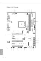
1.3 Motherboard Layout 1 23 4 5 67 BIOS _FB1 M2_WIFI_1 ATX12V1 CHA_FAN3/WP ATX12V2 RoHS CPU_FAN1 CPU_FAN2/WP PS2 Keyboard /Mouse USB 3.2 Gen1 T: USB1 B: USB2 ATXPWR1 X570 Taichi DDR4_A1 (64 bit, 288-pin module) DDR4_A2 (64 bit, 288-pin module) ...FRONT Bottom: MIC IN USB_5 1 CHA_FAN1/WP AMD_FAN_LED1 M2_1 32 PCIE1 1 CHA_FAN4 /WP SPI_TPM_J1 1 F_USB31_TC_1 CMOS Battery PCIE2 AMD M2_2 Premium BIOS ROM X570 SATA3_1_2 SATA3_3_4 SATA3_5_6 Purity SoundTM 4 PCIE3 PCIE4 M2_3 SATA3_7_8 HD_AUDIO1 1 1 T B1 PCIE5 ADDR_LED1 1 CHA_FAN2/WP SPK_PLED1 RGB_HEADER1 1 1 ...
1.3 Motherboard Layout 1 23 4 5 67 BIOS _FB1 M2_WIFI_1 ATX12V1 CHA_FAN3/WP ATX12V2 RoHS CPU_FAN1 CPU_FAN2/WP PS2 Keyboard /Mouse USB 3.2 Gen1 T: USB1 B: USB2 ATXPWR1 X570 Taichi DDR4_A1 (64 bit, 288-pin module) DDR4_A2 (64 bit, 288-pin module) ...FRONT Bottom: MIC IN USB_5 1 CHA_FAN1/WP AMD_FAN_LED1 M2_1 32 PCIE1 1 CHA_FAN4 /WP SPI_TPM_J1 1 F_USB31_TC_1 CMOS Battery PCIE2 AMD M2_2 Premium BIOS ROM X570 SATA3_1_2 SATA3_3_4 SATA3_5_6 Purity SoundTM 4 PCIE3 PCIE4 M2_3 SATA3_7_8 HD_AUDIO1 1 1 T B1 PCIE5 ADDR_LED1 1 CHA_FAN2/WP SPK_PLED1 RGB_HEADER1 1 1 ...


