

User Manual
Page 2
CALIFORNIA, USA ONLY The Lithium battery adopted on this motherboard contains Perchlorate, a toxic substance controlled in advance. "Perchlorate Material-special handling may be liable for any kind, either expressed or ...this documentation. With respect to the contents of this documentation may apply, see www.dtsc.ca.gov/hazardouswaste/ perchlorate" ASRock Website: http://www.asrock.com All rights reserved. ASRock assumes no event shall ASRock, its directors, officers, employees, or agents be reproduced, transcribed, transmitted, or translated in any language, in any...
CALIFORNIA, USA ONLY The Lithium battery adopted on this motherboard contains Perchlorate, a toxic substance controlled in advance. "Perchlorate Material-special handling may be liable for any kind, either expressed or ...this documentation. With respect to the contents of this documentation may apply, see www.dtsc.ca.gov/hazardouswaste/ perchlorate" ASRock Website: http://www.asrock.com All rights reserved. ASRock assumes no event shall ASRock, its directors, officers, employees, or agents be reproduced, transcribed, transmitted, or translated in any language, in any...

User Manual
Page 6
... 8 1.4 I/O Panel 10 Chapter 2 Installation 14 2.1 Removing the Water-cooling Module 15 2.4 Installing Memory Modules (DIMM) 28 2.5 Installing the Motherboard 31 2.6 Expansion Slots (PCI Express Slots) 32 2.7 Connecting Graphics Card to DisplayPort Input 34 2.8 Onboard Headers and Connectors 36 2.9 Smart Switches 42 2.10 Dr. Debug ...
... 8 1.4 I/O Panel 10 Chapter 2 Installation 14 2.1 Removing the Water-cooling Module 15 2.4 Installing Memory Modules (DIMM) 28 2.5 Installing the Motherboard 31 2.6 Expansion Slots (PCI Express Slots) 32 2.7 Connecting Graphics Card to DisplayPort Input 34 2.8 Onboard Headers and Connectors 36 2.9 Smart Switches 42 2.10 Dr. Debug ...
User Manual
Page 9
... the BIOS software might be available on ASRock's website as well. If you are using. ASRock website http://www.asrock.com. 1.1 Package Contents • ASRock X570 AQUA Motherboard (EATX Form Factor) • ASRock X570 AQUA Quick Installation Guide • ASRock X570 AQUA Support CD • 4 x Serial ATA (SATA) Data Cables (Optional) • 1 x ASRock SLI_HB_Bridge_2S Card (Optional) • 1 x ASRock WiFi 2.4/5 GHz Antenna (Optional) • 1 x Right Angle...
... the BIOS software might be available on ASRock's website as well. If you are using. ASRock website http://www.asrock.com. 1.1 Package Contents • ASRock X570 AQUA Motherboard (EATX Form Factor) • ASRock X570 AQUA Quick Installation Guide • ASRock X570 AQUA Support CD • 4 x Serial ATA (SATA) Data Cables (Optional) • 1 x ASRock SLI_HB_Bridge_2S Card (Optional) • 1 x ASRock WiFi 2.4/5 GHz Antenna (Optional) • 1 x Right Angle...
User Manual
Page 16
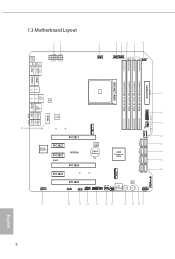
1.3 Motherboard Layout 12 BIOS _FB1 M2_WIFI_1 ATX12V1 ATX12V2 3 4 56 7 8 CHA_FAN3/WP CPU_FAN2/WP CPU_FAN1 AMD_FAN_LED1 1 PS2 Keyboard /Mouse USB 3.2 Gen1 T: USB1 B: USB2 DPIN1 HDMI1 ATXPWR1 DDR4_A1 (... Bottom: Optical SPDIF Top: Center: FRONT Bottom: MIC IN 28 PCIE1 Purity SoundTM 4 PCIE2 PCIE3 RoHS PCIE4 PCIE5 M2_1 BIOS ROM CMOS Battery AMD Premium X570 SATA3_A3_A4 SATA3_A1_A2 SATA3_3_4 SATA3_1_2 9 10 USB3_7_8 1 CHA_FAN1 /WP F_USB31_TC_1 11 12 13 14 15 16 M2_2 HD_AUDIO1 1 PCIE6 RGB_LED1 1 USB_1_2 ADDR_LED1 1 1 1 USB3_9_10 CHA_FAN2 Dr. /WP...
1.3 Motherboard Layout 12 BIOS _FB1 M2_WIFI_1 ATX12V1 ATX12V2 3 4 56 7 8 CHA_FAN3/WP CPU_FAN2/WP CPU_FAN1 AMD_FAN_LED1 1 PS2 Keyboard /Mouse USB 3.2 Gen1 T: USB1 B: USB2 DPIN1 HDMI1 ATXPWR1 DDR4_A1 (... Bottom: Optical SPDIF Top: Center: FRONT Bottom: MIC IN 28 PCIE1 Purity SoundTM 4 PCIE2 PCIE3 RoHS PCIE4 PCIE5 M2_1 BIOS ROM CMOS Battery AMD Premium X570 SATA3_A3_A4 SATA3_A1_A2 SATA3_3_4 SATA3_1_2 9 10 USB3_7_8 1 CHA_FAN1 /WP F_USB31_TC_1 11 12 13 14 15 16 M2_2 HD_AUDIO1 1 PCIE6 RGB_LED1 1 USB_1_2 ADDR_LED1 1 1 1 USB3_9_10 CHA_FAN2 Dr. /WP...

User Manual
Page 20
... and ensures extraordinary low power consumption for WiFi 802.11 a/b/ g/n/ax connectivity standards and Bluetooth v5.0. ASRock WiFi 2.4/5 GHz Antenna 12 English 1.5 WiFi-802.11ax Module and ASRock WiFi 2.4/5 GHz Antenna WiFi-802.11ax + BT Module This motherboard comes with an exclusive WiFi 802.11 a/b/g/n/ax + BT v5.0 module (pre-installed on the...
... and ensures extraordinary low power consumption for WiFi 802.11 a/b/ g/n/ax connectivity standards and Bluetooth v5.0. ASRock WiFi 2.4/5 GHz Antenna 12 English 1.5 WiFi-802.11ax Module and ASRock WiFi 2.4/5 GHz Antenna WiFi-802.11ax + BT Module This motherboard comes with an exclusive WiFi 802.11 a/b/g/n/ax + BT v5.0 module (pre-installed on the...

User Manual
Page 22
...wrist strap or touch a safety grounded object before installing or removing the motherboard. Pre-installation Precautions Take note of your motherboard directly on a grounded anti-static pad or in the bag that the motherboard fits into it. Failure to unplug the power cord before you handle ...to ensure that comes with the components. • When placing screws to secure the motherboard to you install the motherboard, study the configuration of the following precautions before you uninstall any motherboard settings. • Make sure to do not overtighten the screws! Doing so may...
...wrist strap or touch a safety grounded object before installing or removing the motherboard. Pre-installation Precautions Take note of your motherboard directly on a grounded anti-static pad or in the bag that the motherboard fits into it. Failure to unplug the power cord before you handle ...to ensure that comes with the components. • When placing screws to secure the motherboard to you install the motherboard, study the configuration of the following precautions before you uninstall any motherboard settings. • Make sure to do not overtighten the screws! Doing so may...

User Manual
Page 25
The positions are indicated as below. 17 English X570 AQUA Please unscrew the ten screws from the bottom side of the motherboard to release the backplate and the water-cooling module.
The positions are indicated as below. 17 English X570 AQUA Please unscrew the ten screws from the bottom side of the motherboard to release the backplate and the water-cooling module.

User Manual
Page 26
3 Removing the Water-cooling Module B A AQUA_LED1 AQUA_LED1 Unplug the LED Plug from the motherboard before removing the Water-cooling Module. 18 English
3 Removing the Water-cooling Module B A AQUA_LED1 AQUA_LED1 Unplug the LED Plug from the motherboard before removing the Water-cooling Module. 18 English

User Manual
Page 36
...dual channel configuration, you install the memory modules on DDR4_A2 and DDR4_B2 first for better DRAM compatibility on 2 DIMMs configuration. otherwise, this motherboard and DIMM may be damaged. 4. DR - DR 3200 SR SR SR SR 2933 SR/DR DR SR/DR DR 2667 SR/... (Matisse): UDIMM Memory Slot A1 A2 B1 B2 Frequency (Mhz) - DR - - 3200 - SR 2933 - SR - 2.4 Installing Memory Modules (DIMM) This motherboard provides four 288-pin DDR4 (Double Data Rate 4) DIMM slots, and supports Dual Channel Memory Technology. 1. It is not allowed to install identical (the same...
...dual channel configuration, you install the memory modules on DDR4_A2 and DDR4_B2 first for better DRAM compatibility on 2 DIMMs configuration. otherwise, this motherboard and DIMM may be damaged. 4. DR - DR 3200 SR SR SR SR 2933 SR/DR DR SR/DR DR 2667 SR/... (Matisse): UDIMM Memory Slot A1 A2 B1 B2 Frequency (Mhz) - DR - - 3200 - SR 2933 - SR - 2.4 Installing Memory Modules (DIMM) This motherboard provides four 288-pin DDR4 (Double Data Rate 4) DIMM slots, and supports Dual Channel Memory Technology. 1. It is not allowed to install identical (the same...

User Manual
Page 38
It will cause permanent damage to the motherboard and the DIMM if you force the DIMM into the slot at incorrect orientation. 1 2 3 30 English The DIMM only fits in one correct orientation.
It will cause permanent damage to the motherboard and the DIMM if you force the DIMM into the slot at incorrect orientation. 1 2 3 30 English The DIMM only fits in one correct orientation.

User Manual
Page 39
2.5 Installing the Motherboard 1 A B X570 AQUA 2 English 31
2.5 Installing the Motherboard 1 A B X570 AQUA 2 English 31

User Manual
Page 40
... (PCIe 4.0 x16 slot) is used for the card before you start the installation. 2.6 Expansion Slots (PCI Express Slots) There are 6 PCI Express slots on the motherboard.
... (PCIe 4.0 x16 slot) is used for the card before you start the installation. 2.6 Expansion Slots (PCI Express Slots) There are 6 PCI Express slots on the motherboard.

User Manual
Page 41
English 33 X570 AQUA Ryzen series CPUs (Pinnacle Ridge) Single Graphics Card PCIE1 Gen3x16 Two Graphics Cards in CrossFireXTM or SLITM Mode Gen3x8 PCIE4 N/A Gen3x8 Three Graphics Cards in 3-Way CrossFireXTM Mode Gen3x8 Gen3x8 PCIE6 N/A N/A Gen4x4 Ryzen series CPUs (Picasso) Single Graphics Card PCIE1 Gen3x8 N/A PCIE4 N/A N/A PCIE6 N/A Gen4x4 For a better thermal environment, please connect a chassis fan to the motherboard's chassis fan connector (CHA_FAN1/WP, CHA_FAN2/WP or CHA_FAN3/WP) when using multiple graphics cards.
English 33 X570 AQUA Ryzen series CPUs (Pinnacle Ridge) Single Graphics Card PCIE1 Gen3x16 Two Graphics Cards in CrossFireXTM or SLITM Mode Gen3x8 PCIE4 N/A Gen3x8 Three Graphics Cards in 3-Way CrossFireXTM Mode Gen3x8 Gen3x8 PCIE6 N/A N/A Gen4x4 Ryzen series CPUs (Picasso) Single Graphics Card PCIE1 Gen3x8 N/A PCIE4 N/A N/A PCIE6 N/A Gen4x4 For a better thermal environment, please connect a chassis fan to the motherboard's chassis fan connector (CHA_FAN1/WP, CHA_FAN2/WP or CHA_FAN3/WP) when using multiple graphics cards.

User Manual
Page 42
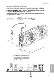
Then connect the other end of the DisplayPort Cable to the DisplayPort Port (B) on the graphics card. 2.7 Connecting Graphics Card to DisplayPort Input Connecting a Graphics Card to DPIN1 Connect one end of the cable to the DisplayPort IN Port (A) on the motherboard's rear I/O panel. DisplayPort Cable B A DPIN1 For USB Type C Monitor Connection: Input DP_IN1 Output TB_1 DP_IN1 34 TB_1 English
Then connect the other end of the DisplayPort Cable to the DisplayPort Port (B) on the graphics card. 2.7 Connecting Graphics Card to DisplayPort Input Connecting a Graphics Card to DPIN1 Connect one end of the cable to the DisplayPort IN Port (A) on the motherboard's rear I/O panel. DisplayPort Cable B A DPIN1 For USB Type C Monitor Connection: Input DP_IN1 Output TB_1 DP_IN1 34 TB_1 English
User Manual
Page 43
Mini DisplayPort to DisplayPort Adapter Cable A B DPIN2 For USB Type C Monitor Connection: Input DP_IN2 Output TB_2 TB_2 35 English Then connect the other end of the Mini DisplayPort to DisplayPort Adapter Cable to the internal Mini DisplayPort Port (A) on the motherboard. * The internal Mini DisplayPort IN Port is only compatible with the ASRock graphics card with the internal Mini DisplayPort OUT Port. X570 AQUA Connecting a Graphics Card to DPIN2 Connect one end of the cable to the onboard DisplayPort Port (B) on the graphics card.
Mini DisplayPort to DisplayPort Adapter Cable A B DPIN2 For USB Type C Monitor Connection: Input DP_IN2 Output TB_2 TB_2 35 English Then connect the other end of the Mini DisplayPort to DisplayPort Adapter Cable to the internal Mini DisplayPort Port (A) on the motherboard. * The internal Mini DisplayPort IN Port is only compatible with the ASRock graphics card with the internal Mini DisplayPort OUT Port. X570 AQUA Connecting a Graphics Card to DPIN2 Connect one end of the cable to the onboard DisplayPort Port (B) on the graphics card.

User Manual
Page 44
... damage to the power button on the chassis to turn off when the system is reading or writing data. PWRBTN (Power Button): Connect to the motherboard.
... damage to the power button on the chassis to turn off when the system is reading or writing data. PWRBTN (Power Button): Connect to the motherboard.

User Manual
Page 45
... p.8, No. 10) Vbus IntA_PA_SSRXIntA_PA_SSRX+ GND IntA_PA_SSTXIntA_PA_SSTX+ GND IntA_PA_DIntA_PA_D+ Vbus IntA_PB_SSRXIntA_PB_SSRX+ GND IntA_PB_SSTXIntA_PB_SSTX+ GND IntA_PB_DIntA_PB_D+ Dummy 1 There is a header on this motherboard. SATA3_A4 SATA3_A2 SATA3_4 SATA3_2 SATA3_A3 SATA3_A1 SATA3_3 SATA3_1 English X570 AQUA Power LED and Speaker Header (7-pin SPK_PLED1) (see p.8, No. 16) Please connect the chassis power LED and the chassis speaker to...
... p.8, No. 10) Vbus IntA_PA_SSRXIntA_PA_SSRX+ GND IntA_PA_SSTXIntA_PA_SSTX+ GND IntA_PA_DIntA_PA_D+ Vbus IntA_PB_SSRXIntA_PB_SSRX+ GND IntA_PB_SSTXIntA_PB_SSTX+ GND IntA_PB_DIntA_PB_D+ Dummy 1 There is a header on this motherboard. SATA3_A4 SATA3_A2 SATA3_4 SATA3_2 SATA3_A3 SATA3_A1 SATA3_3 SATA3_1 English X570 AQUA Power LED and Speaker Header (7-pin SPK_PLED1) (see p.8, No. 16) Please connect the chassis power LED and the chassis speaker to...

User Manual
Page 46
... Type C USB 3.2 Gen2 Header on the chassis must support HDA to function correctly. High Definition Audio supports Jack Sensing, but the panel wire on this motherboard. Connect Mic_IN (MIC) to Ground (GND). Please follow the instructions in the Realtek Control panel and adjust "Recording Volume". Connect Audio_R (RIN) to OUT2_R and...
... Type C USB 3.2 Gen2 Header on the chassis must support HDA to function correctly. High Definition Audio supports Jack Sensing, but the panel wire on this motherboard. Connect Mic_IN (MIC) to Ground (GND). Please follow the instructions in the Realtek Control panel and adjust "Recording Volume". Connect Audio_R (RIN) to OUT2_R and...

User Manual
Page 47
... 1-3. CPU Water Pump Fan Connector (4-pin CPU_FAN2/WP) (see p.8, No. 5) FAN_SPEED_CONTROL CPU_FAN_SPEED FAN_VOLTAGE GND 1 2 34 This motherboard provides a 4-Pin CPU fan (Quiet Fan) connector. X570 AQUA Chassis Water Pump Fan Connectors (4-pin CHA_FAN1/WP) (see p.8, No. 11) (4-pin CHA_FAN2/WP) (see p.8, No. 22...) (4-pin CHA_FAN3/WP) (see p.8, No. 9) 12 24 1 13 This motherboard provides a 24-pin ATX power connector. If you...
... 1-3. CPU Water Pump Fan Connector (4-pin CPU_FAN2/WP) (see p.8, No. 5) FAN_SPEED_CONTROL CPU_FAN_SPEED FAN_VOLTAGE GND 1 2 34 This motherboard provides a 4-Pin CPU fan (Quiet Fan) connector. X570 AQUA Chassis Water Pump Fan Connectors (4-pin CHA_FAN1/WP) (see p.8, No. 11) (4-pin CHA_FAN2/WP) (see p.8, No. 22...) (4-pin CHA_FAN3/WP) (see p.8, No. 9) 12 24 1 13 This motherboard provides a 24-pin ATX power connector. If you...

User Manual
Page 48
... Power Connector (8-pin ATX12V1) (see p.8, No. 1) 8 5 4 1 ATX 12V Power Connector (4-pin ATX12V2) (see p.8, No. 2) AMD FAN LED Header (4-pin AMD_FAN_ LED1) (see p.8, No. 8) 1 12V G R B This motherboard provides an 8-pin ATX 12V power connector. English 40 AMD FAN LED Header is compatible with AMD heatsink. The cable connection allows users to this...
... Power Connector (8-pin ATX12V1) (see p.8, No. 1) 8 5 4 1 ATX 12V Power Connector (4-pin ATX12V2) (see p.8, No. 2) AMD FAN LED Header (4-pin AMD_FAN_ LED1) (see p.8, No. 8) 1 12V G R B This motherboard provides an 8-pin ATX 12V power connector. English 40 AMD FAN LED Header is compatible with AMD heatsink. The cable connection allows users to this...


