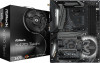
Quick Installation Guide
Page 4
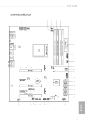
Motherboard Layout 1 23 X470 Taichi 4 5 67 M2_WIFI_1 ATX12V1 CHA_FAN3/WP ATX12V2 CPU_FAN1 CPU_FAN2/WP PS2 Keyboard /Mouse USB 3.1 Gen1 T: USB1 B: USB2 SOCKET AM4 CLRC BTN1 HDMI1 USB 3.1 Gen1 Top: T: USB3... CMOS Battery BIOS ROM AUDIO CODEC PCIE3 AMD Promontory X470 DDR4_A1 (64 bit, 288-pin module) DDR4_A2 (64 bit, 288-pin module) DDR4_B1 (64 bit, 288-pin module) DDR4_B2 (64 bit, 288-pin module) SATA3_1_2 USB3_9_10 ATXPWR1 USB3_7_8 1 CHA_FAN1/WP F_USB31_TC_1 1 SATA3_3_4 SATA3_5_6 M2_2 PCIE4 HD_AUDIO1 1 X470 Taichi PCIE5 ADDR_LED1 1 RGB_LED1 1 CHA_FAN2/WP SPK_PLED1...
Motherboard Layout 1 23 X470 Taichi 4 5 67 M2_WIFI_1 ATX12V1 CHA_FAN3/WP ATX12V2 CPU_FAN1 CPU_FAN2/WP PS2 Keyboard /Mouse USB 3.1 Gen1 T: USB1 B: USB2 SOCKET AM4 CLRC BTN1 HDMI1 USB 3.1 Gen1 Top: T: USB3... CMOS Battery BIOS ROM AUDIO CODEC PCIE3 AMD Promontory X470 DDR4_A1 (64 bit, 288-pin module) DDR4_A2 (64 bit, 288-pin module) DDR4_B1 (64 bit, 288-pin module) DDR4_B2 (64 bit, 288-pin module) SATA3_1_2 USB3_9_10 ATXPWR1 USB3_7_8 1 CHA_FAN1/WP F_USB31_TC_1 1 SATA3_3_4 SATA3_5_6 M2_2 PCIE4 HD_AUDIO1 1 X470 Taichi PCIE5 ADDR_LED1 1 RGB_LED1 1 CHA_FAN2/WP SPK_PLED1...
Quick Installation Guide
Page 35
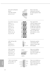
... 22) GND P+ PUSB_PWR 1 USB_PWR PP+ GND DUMMY 1 GND P+ PUSB_PWR This header is used for your SSDs. There are two headers on this motherboard. Each USB 2.0 header can support two ports. 32 English Please connect the chassis power LED and the chassis speaker to 6.0 Gb/s data transfer rate.... * To minimize the boot time, use AMD SATA ports (SATA3_1~6) for connecting the USB connector on this motherboard. USB 3.1 Gen1 Headers (19-pin USB3_7_8) (see p.1, No. 18) SPEAKER DUMMY DUMMY +5V 1 PLED+ PLED...
... 22) GND P+ PUSB_PWR 1 USB_PWR PP+ GND DUMMY 1 GND P+ PUSB_PWR This header is used for your SSDs. There are two headers on this motherboard. Each USB 2.0 header can support two ports. 32 English Please connect the chassis power LED and the chassis speaker to 6.0 Gb/s data transfer rate.... * To minimize the boot time, use AMD SATA ports (SATA3_1~6) for connecting the USB connector on this motherboard. USB 3.1 Gen1 Headers (19-pin USB3_7_8) (see p.1, No. 18) SPEAKER DUMMY DUMMY +5V 1 PLED+ PLED...
Quick Installation Guide
Page 38
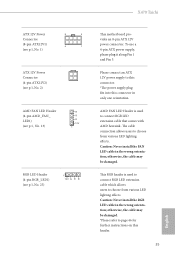
...*The power supply plug fits into this header. 35 English Caution: Never install the RGB LED cable in the wrong orientation; AMD FAN LED Header is used to page 46 for further instructions on this connector in only one orientation. Caution: Never install the ...Pin 1 and Pin 5. X470 Taichi ATX 12V Power Connector (8-pin ATX12V1) (see p.1, No. 1) 8 5 4 1 ATX 12V Power Connector (4-pin ATX12V2) (see p.1, No. 2) AMD FAN LED Header (4-pin AMD_FAN_ LED1) (see p.1, No. 13) B R G 12V 1 RGB LED Header (4-pin RGB_LED1) (see p.1, No. 25) 1 12V G R B This motherboard provides an 8-pin ATX ...
...*The power supply plug fits into this header. 35 English Caution: Never install the RGB LED cable in the wrong orientation; AMD FAN LED Header is used to page 46 for further instructions on this connector in only one orientation. Caution: Never install the ...Pin 1 and Pin 5. X470 Taichi ATX 12V Power Connector (8-pin ATX12V1) (see p.1, No. 1) 8 5 4 1 ATX 12V Power Connector (4-pin ATX12V2) (see p.1, No. 2) AMD FAN LED Header (4-pin AMD_FAN_ LED1) (see p.1, No. 13) B R G 12V 1 RGB LED Header (4-pin RGB_LED1) (see p.1, No. 25) 1 12V G R B This motherboard provides an 8-pin ATX ...
User Manual
Page 16
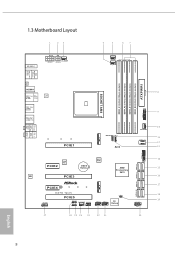
1.3 Motherboard Layout 1 23 4 5 67 M2_WIFI_1 ATX12V1 CHA_FAN3/WP ATX12V2 CPU_FAN1 CPU_FAN2/WP PS2 Keyboard /Mouse USB 3.1 Gen1 T: USB1 B: USB2 SOCKET AM4 CLRC BTN1 HDMI1 USB 3.1 Gen1 ... I/O CMOS Battery BIOS ROM AUDIO CODEC PCIE3 AMD Promontory X470 DDR4_A1 (64 bit, 288-pin module) DDR4_A2 (64 bit, 288-pin module) DDR4_B1 (64 bit, 288-pin module) DDR4_B2 (64 bit, 288-pin module) SATA3_1_2 USB3_9_10 ATXPWR1 USB3_7_8 1 CHA_FAN1/WP F_USB31_TC_1 1 SATA3_3_4 SATA3_5_6 M2_2 PCIE4 HD_AUDIO1 1 X470 Taichi PCIE5 ADDR_LED1 1 RGB_LED1 1 CHA_FAN2/WP SPK_PLED1...
1.3 Motherboard Layout 1 23 4 5 67 M2_WIFI_1 ATX12V1 CHA_FAN3/WP ATX12V2 CPU_FAN1 CPU_FAN2/WP PS2 Keyboard /Mouse USB 3.1 Gen1 T: USB1 B: USB2 SOCKET AM4 CLRC BTN1 HDMI1 USB 3.1 Gen1 ... I/O CMOS Battery BIOS ROM AUDIO CODEC PCIE3 AMD Promontory X470 DDR4_A1 (64 bit, 288-pin module) DDR4_A2 (64 bit, 288-pin module) DDR4_B1 (64 bit, 288-pin module) DDR4_B2 (64 bit, 288-pin module) SATA3_1_2 USB3_9_10 ATXPWR1 USB3_7_8 1 CHA_FAN1/WP F_USB31_TC_1 1 SATA3_3_4 SATA3_5_6 M2_2 PCIE4 HD_AUDIO1 1 X470 Taichi PCIE5 ADDR_LED1 1 RGB_LED1 1 CHA_FAN2/WP SPK_PLED1...

User Manual
Page 40
... Gb/s data transfer rate. * To minimize the boot time, use AMD SATA ports (SATA3_1~6) for your SSDs. These eight SATA3 connectors support SATA data cables for connecting the USB connector on this motherboard. Each USB 3.1 Gen1 header can support two ports. There are two ... GND P+ PUSB_PWR 1 USB_PWR PP+ GND DUMMY 1 GND P+ PUSB_PWR This header is used for internal storage devices with up to this motherboard. SATA3_A2 SATA3_6 SATA3_4 SATA3_2 SATA3_A1 SATA3_5 SATA3_3 SATA3_1 AMD LED Fan USB Header (4-pin USB_5) (see p.8, No. 11) USB 2.0 Headers (9-pin USB_1_2) (see p.8, No. 21) (9-pin...
... Gb/s data transfer rate. * To minimize the boot time, use AMD SATA ports (SATA3_1~6) for your SSDs. These eight SATA3 connectors support SATA data cables for connecting the USB connector on this motherboard. Each USB 3.1 Gen1 header can support two ports. There are two ... GND P+ PUSB_PWR 1 USB_PWR PP+ GND DUMMY 1 GND P+ PUSB_PWR This header is used for internal storage devices with up to this motherboard. SATA3_A2 SATA3_6 SATA3_4 SATA3_2 SATA3_A1 SATA3_5 SATA3_3 SATA3_1 AMD LED Fan USB Header (4-pin USB_5) (see p.8, No. 11) USB 2.0 Headers (9-pin USB_1_2) (see p.8, No. 21) (9-pin...

User Manual
Page 43
X470 Taichi ATX 12V Power Connector (8-pin ATX12V1) (see p.8, No. 1) 8 5 4 1 ATX 12V Power Connector (4-pin ATX12V2) (see p.8, No. 2) AMD FAN LED Header (4-pin AMD_FAN_ LED1) (see p.8, No. 13) B R G 12V 1 RGB LED Header (4-pin RGB_LED1) (see p.8, No. 25) 1 12V G R B This motherboard provides an 8-pin ATX 12V power ...RGB header is used to connect RGB LED extension cable which allows users to connect RGB LED extension cable that comes with AMD heatsink. AMD FAN LED Header is used to choose from various LED lighting effects. To use a 4-pin ATX power supply, please plug...
X470 Taichi ATX 12V Power Connector (8-pin ATX12V1) (see p.8, No. 1) 8 5 4 1 ATX 12V Power Connector (4-pin ATX12V2) (see p.8, No. 2) AMD FAN LED Header (4-pin AMD_FAN_ LED1) (see p.8, No. 13) B R G 12V 1 RGB LED Header (4-pin RGB_LED1) (see p.8, No. 25) 1 12V G R B This motherboard provides an 8-pin ATX 12V power ...RGB header is used to connect RGB LED extension cable which allows users to connect RGB LED extension cable that comes with AMD heatsink. AMD FAN LED Header is used to choose from various LED lighting effects. To use a 4-pin ATX power supply, please plug...
User Manual
Page 51
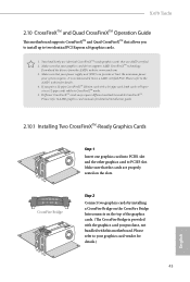
...on the CrossFire Bridge Interconnects on the slots. Please refer to PCIE3 slot. Make sure that your graphics card driver supports AMD CrossFireXTM technology. Make sure that your power supply unit (PSU) can provide at least the minimum power your graphics card vendor...Bridge is recommended to two identical PCI Express x16 graphics cards. 1. You should only use a AMD certified PSU. X470 Taichi 2.10 CrossFireXTM and Quad CrossFireXTM Operation Guide This motherboard supports CrossFireXTM and Quad CrossFireXTM that allows you pair a 12-pipe CrossFireXTM Edition card with this...
...on the CrossFire Bridge Interconnects on the slots. Please refer to PCIE3 slot. Make sure that your graphics card driver supports AMD CrossFireXTM technology. Make sure that your power supply unit (PSU) can provide at least the minimum power your graphics card vendor...Bridge is recommended to two identical PCI Express x16 graphics cards. 1. You should only use a AMD certified PSU. X470 Taichi 2.10 CrossFireXTM and Quad CrossFireXTM Operation Guide This motherboard supports CrossFireXTM and Quad CrossFireXTM that allows you pair a 12-pipe CrossFireXTM Edition card with this...


