
User Manual
Page 3
... Guide 27 2.11 Serial ATA (SATA) / Serial ATAII (SATAII) Hard Disks Installation 28 2.12 Driver Installation Guide 28 2.13 Untied Overclocking Technology 28 3 BIOS SETUP UTILITY 29 3.1 Introduction 29 3.1.1 BIOS Menu Bar 29 3.1.2 Navigation Keys 30 3.2 Main Screen 30 3.3 Smart Screen 31 3.4 Advanced Screen 32 3.4.1 CPU Configuration 32 3.4.2 Chipset Configuration 34 3.4.3 ACPI...
... Guide 27 2.11 Serial ATA (SATA) / Serial ATAII (SATAII) Hard Disks Installation 28 2.12 Driver Installation Guide 28 2.13 Untied Overclocking Technology 28 3 BIOS SETUP UTILITY 29 3.1 Introduction 29 3.1.1 BIOS Menu Bar 29 3.1.2 Navigation Keys 30 3.2 Main Screen 30 3.3 Smart Screen 31 3.4 Advanced Screen 32 3.4.1 CPU Configuration 32 3.4.2 Chipset Configuration 34 3.4.3 ACPI...

User Manual
Page 5
.... Chapter 3 and 4 contain the configuration guide to BIOS setup and information of the motherboard and step-by-step guide to quality and endurance. www.asrock.com/support/index.asp 1.1 Package Contents ASRock P5B Pro Motherboard (ATX Form Factor: 12.0-in x 8.0-in, 30.5 cm x 20.3 cm) ASRock P5B Pro Quick Installation Guide ASRock P5B Pro Support CD One 80-conductor Ultra ATA...
.... Chapter 3 and 4 contain the configuration guide to BIOS setup and information of the motherboard and step-by-step guide to quality and endurance. www.asrock.com/support/index.asp 1.1 Package Contents ASRock P5B Pro Motherboard (ATX Form Factor: 12.0-in x 8.0-in, 30.5 cm x 20.3 cm) ASRock P5B Pro Quick Installation Guide ASRock P5B Pro Support CD One 80-conductor Ultra ATA...

User Manual
Page 7
..., WHQL * For detailed product information, please visit our website: http://www.asrock.com 7 AMI Legal BIOS - Intelligent Energy Saver (see CAUTION 9) - ASRock U-COP (see CAUTION 8) BIOS Feature - 4Mb AMI BIOS - Drivers, Utilities, AntiVirus Software (Trial Version) Unique Feature - Microsoft®... 2.0 headers (support 4 USB 2.0 ports) (see CAUTION 13) - CPU Frequency Stepless Control (see CAUTION 11) - CD in header - ASRock Instant Flash (see CAUTION 12) - Boot Failure Guard (B.F.G.) Hardware - Voltage Monitoring: +12V, +5V, +3.3V, Vcore OS - CPU, DRAM...
..., WHQL * For detailed product information, please visit our website: http://www.asrock.com 7 AMI Legal BIOS - Intelligent Energy Saver (see CAUTION 9) - ASRock U-COP (see CAUTION 8) BIOS Feature - 4Mb AMI BIOS - Drivers, Utilities, AntiVirus Software (Trial Version) Unique Feature - Microsoft®... 2.0 headers (support 4 USB 2.0 ports) (see CAUTION 13) - CPU Frequency Stepless Control (see CAUTION 11) - CD in header - ASRock Instant Flash (see CAUTION 12) - Boot Failure Guard (B.F.G.) Hardware - Voltage Monitoring: +12V, +5V, +3.3V, Vcore OS - CPU, DRAM...
User Manual
Page 8
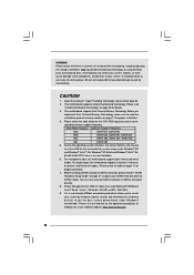
... CAUTION! 1. sponding memory support frequency. bit with overclocking, including adjusting the setting in the BIOS, applying Untied Overclocking Technology, or using the thirdparty overclocking tools. ASRock website: http://www.asrock.com 8 For Windows® XP 64-bit and Windows® VistaTM 64- It should ...174; XP and Windows® VistaTM. Before installing SATAII hard disk to SATAII connector, please read the installation guide of ASRock OC Tuner. About the setting of your own risk and expense. Due to the operating system limitation, the actual memory...
... CAUTION! 1. sponding memory support frequency. bit with overclocking, including adjusting the setting in the BIOS, applying Untied Overclocking Technology, or using the thirdparty overclocking tools. ASRock website: http://www.asrock.com 8 For Windows® XP 64-bit and Windows® VistaTM 64- It should ...174; XP and Windows® VistaTM. Before installing SATAII hard disk to SATAII connector, please read the installation guide of ASRock OC Tuner. About the setting of your own risk and expense. Due to the operating system limitation, the actual memory...
User Manual
Page 9
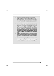
... other than the recommended CPU bus frequencies may cause the instability of Intelligent Energy Saver. In other complicated flash utility. ASRock website: http://www.asrock.com 11. With this tool and save the new BIOS file to your USB flash drive, floppy disk or hard drive, then you can update your... in Flash ROM. Just launch this utility, you can press key during the POST or press key to BIOS setup menu to access ASRock Instant Flash. ASRock Instant Flash is able to spray thermal grease between the CPU and the heatsink when you resume the system, please check if the ...
... other than the recommended CPU bus frequencies may cause the instability of Intelligent Energy Saver. In other complicated flash utility. ASRock website: http://www.asrock.com 11. With this tool and save the new BIOS file to your USB flash drive, floppy disk or hard drive, then you can update your... in Flash ROM. Just launch this utility, you can press key during the POST or press key to BIOS setup menu to access ASRock Instant Flash. ASRock Instant Flash is able to spray thermal grease between the CPU and the heatsink when you resume the system, please check if the ...

User Manual
Page 10
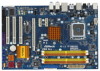
...LAN PHY CD1 PCIE1 PCIE2 Intel P965 Chipset PCIE3 AUDIO CODEC HDMI_SPDIF1 1 HD_AUDIO1 1 Super IO COM1 1 FLOPPY1 PCI1 4Mb BIOS PCI2 PCI3 LPT1 RoHS P5B Pro DDRII_1 (64 bit, 240-piFnSmBod8ul0e)0 DDRII_2 (64 bit, 240-piFnSmBod8ul0e)0 IDE1 Intel ICH8 FRONT_1394 1 CHA_FAN1 CMOS Battery CLRCMOS1 ...Floppy Connector (FLOPPY1) COM Port Header (COM1) PCI Slots (PCI1- 3) Front Panel Audio Header (HD_AUDIO1, Lime) HDMI_SPDIF Header (HDMI_SPDIF1, Yellow) BIOS SPI Chip PCI Express x16 Slot (PCIE3) Internal Audio Connector: CD1 (Black) PCI Express x1 Slot (PCIE2) PCI Express x1 Slot (PCIE1)...
...LAN PHY CD1 PCIE1 PCIE2 Intel P965 Chipset PCIE3 AUDIO CODEC HDMI_SPDIF1 1 HD_AUDIO1 1 Super IO COM1 1 FLOPPY1 PCI1 4Mb BIOS PCI2 PCI3 LPT1 RoHS P5B Pro DDRII_1 (64 bit, 240-piFnSmBod8ul0e)0 DDRII_2 (64 bit, 240-piFnSmBod8ul0e)0 IDE1 Intel ICH8 FRONT_1394 1 CHA_FAN1 CMOS Battery CLRCMOS1 ...Floppy Connector (FLOPPY1) COM Port Header (COM1) PCI Slots (PCI1- 3) Front Panel Audio Header (HD_AUDIO1, Lime) HDMI_SPDIF Header (HDMI_SPDIF1, Yellow) BIOS SPI Chip PCI Express x16 Slot (PCIE3) Internal Audio Connector: CD1 (Black) PCI Express x1 Slot (PCIE2) PCI Express x1 Slot (PCIE1)...

User Manual
Page 22
... control of printer devices. MIC_RET and OUT_RET are two USB 2.0 headers on the chassis must support HDA to OUT2_L. You don't need to MIC2_L. Enter BIOS Setup Utility. D. If you to receive stereo audio input from [Auto] to Ground (GND). Each USB 2.0 header can support two USB 2.0 ports. Please follow the...
... control of printer devices. MIC_RET and OUT_RET are two USB 2.0 headers on the chassis must support HDA to OUT2_L. You don't need to MIC2_L. Enter BIOS Setup Utility. D. If you to receive stereo audio input from [Auto] to Ground (GND). Each USB 2.0 header can support two USB 2.0 ports. Please follow the...

User Manual
Page 28
.... 2.12 Driver Installation Guide To install the drivers to your system, please insert the support CD to your chassis. STEP 4: Connect the other end of BIOS setup to set the selection from up to bottom side to the motherboard's SATAII connector. Before you to [CPU, PCIE, Async.]. Please follow the order...
.... 2.12 Driver Installation Guide To install the drivers to your system, please insert the support CD to your chassis. STEP 4: Connect the other end of BIOS setup to set the selection from up to bottom side to the motherboard's SATAII connector. Before you to [CPU, PCIE, Async.]. Please follow the order...

User Manual
Page 29
...menu bar, and then press to your requirements Advanced To set up the advanced BIOS features H/W Monitor To display current hardware status Boot To set up the security features Exit To exit...the following selections: Main To set up the system time/date information Smart To load the BIOS according to get into the sub screen. 29 Please press during the Power-On-Self-Test... has a menu bar with its test routines. You may not exactly match what you wish to enter the BIOS SETUP UTILITY after POST, restart the system by pressing + + , or by turning the system off and ...
...menu bar, and then press to your requirements Advanced To set up the advanced BIOS features H/W Monitor To display current hardware status Boot To set up the security features Exit To exit...the following selections: Main To set up the system time/date information Smart To load the BIOS according to get into the sub screen. 29 Please press during the Power-On-Self-Test... has a menu bar with its test routines. You may not exactly match what you wish to enter the BIOS SETUP UTILITY after POST, restart the system by pressing + + , or by turning the system off and ...

User Manual
Page 30
...function description of each navigation key. 3.1.2 Navigation Keys Please check the following table for all the settings To save changes and exit the BIOS SETUP UTILITY To jump to the Exit Screen or exit the current screen 3.2 Main Screen When you enter the... UTILITY Main Smart Advanced H/W Monitor Boot Security Exit System Overview System Time System Date [14:00:09] [Wed 04/22/2009] BIOS Version : P5B Pro P1.00 Processor Type : Intel (R) CPU 3.33GHz (64bit) Processor Speed : 3333MHz Microcode Update : F49/3 Cache Size : 256KB Total Memory DDRII_1 DDRII_2 DDRII_3 DDRII_4 : 1024MB ...
...function description of each navigation key. 3.1.2 Navigation Keys Please check the following table for all the settings To save changes and exit the BIOS SETUP UTILITY To jump to the Exit Screen or exit the current screen 3.2 Main Screen When you enter the... UTILITY Main Smart Advanced H/W Monitor Boot Security Exit System Overview System Time System Date [14:00:09] [Wed 04/22/2009] BIOS Version : P5B Pro P1.00 Processor Type : Intel (R) CPU 3.33GHz (64bit) Processor Speed : 3333MHz Microcode Update : F49/3 Cache Size : 256KB Total Memory DDRII_1 DDRII_2 DDRII_3 DDRII_4 : 1024MB ...
User Manual
Page 31
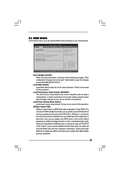
... Smart Advanced H/W Monitor Boot Security Exit Smart Settings Save Changes and Exit Load BIOS Defaults Load Performance Setup Default (IDE/SATA) Load Power Saving Setup Default BIOS Update Utility ASRock Instant Flash Exit system setup after loading, please resume optimal default settings. Just launch...When you can be used for this option, it will show the BIOS files and their respective information. F9 key can be used for this operation. ASRock Instant Flash ASRock Instant Flash is a BIOS flash utility embedded in a few clicks without entering operating systems first ...
... Smart Advanced H/W Monitor Boot Security Exit Smart Settings Save Changes and Exit Load BIOS Defaults Load Performance Setup Default (IDE/SATA) Load Power Saving Setup Default BIOS Update Utility ASRock Instant Flash Exit system setup after loading, please resume optimal default settings. Just launch...When you can be used for this option, it will show the BIOS files and their respective information. F9 key can be used for this operation. ASRock Instant Flash ASRock Instant Flash is a BIOS flash utility embedded in a few clicks without entering operating systems first ...

User Manual
Page 32
...Select Screen Select Item Enter Go to adjust CPU frequency. Overclock Mode Use this section may cause the system to malfunction. 3.4.1 CPU Configuration BIOS SETUP UTILITY Advanced CPU Configuration Overclock Mode CPU Frequency (MHz) PCIE Frequency (MHz) Boot Failure Guard Spread Spectrum [Auto] [133] ... Select Item Change Option General Help Load Defaults Save and Exit Exit v02.54 (C) Copyright 1985-2005, American Megatrends, Inc. BIOS SETUP UTILITY Main Smart Advanced H/W Monitor Boot Security Exit Advanced Settings WARNING : Setting wrong values in this to select Overclock Mode...
...Select Screen Select Item Enter Go to adjust CPU frequency. Overclock Mode Use this section may cause the system to malfunction. 3.4.1 CPU Configuration BIOS SETUP UTILITY Advanced CPU Configuration Overclock Mode CPU Frequency (MHz) PCIE Frequency (MHz) Boot Failure Guard Spread Spectrum [Auto] [133] ... Select Item Change Option General Help Load Defaults Save and Exit Exit v02.54 (C) Copyright 1985-2005, American Megatrends, Inc. BIOS SETUP UTILITY Main Smart Advanced H/W Monitor Boot Security Exit Advanced Settings WARNING : Setting wrong values in this to select Overclock Mode...

User Manual
Page 34
... for this technology, such as "Portable/Laptop" to enable this function. DISABLE: Do not allow remapping of overlapped PCI memory above issue occurs. 3.4.2 Chipset Configuration BIOS SETUP UTILITY Advanced Chipset Settings Memory Remap Feature DRAM Frequency Flexibility Option [Disabled] [Auto] [Disabled] DRAM Timing Control Voltage Control Primary Graphics Adapter [PCI] Onboard...
... for this technology, such as "Portable/Laptop" to enable this function. DISABLE: Do not allow remapping of overlapped PCI memory above issue occurs. 3.4.2 Chipset Configuration BIOS SETUP UTILITY Advanced Chipset Settings Memory Remap Feature DRAM Frequency Flexibility Option [Disabled] [Auto] [Disabled] DRAM Timing Control Voltage Control Primary Graphics Adapter [PCI] Onboard...

User Manual
Page 35
...)], [2.75X (66)], [3.00X (77)], [3.25X (88)], [3.50X (99)], [3.75X (AA)], [4.00X (BB)], [4.25X (CC)], [4.50X (DD)], [4.75X (EE)] and [5.00X (FF)]. 35 DRAM Timing Control BIOS SETUP UTILITY Advanced DRAM Timing Control Current Setting : 4-4-4-12-28-4-2 DRAM tCL [Auto] DRAM tRCD [Auto] DRAM tRP [Auto] DRAM tRAS [Auto] DRAM tRFC [Auto...
...)], [2.75X (66)], [3.00X (77)], [3.25X (88)], [3.50X (99)], [3.75X (AA)], [4.00X (BB)], [4.25X (CC)], [4.50X (DD)], [4.75X (EE)] and [5.00X (FF)]. 35 DRAM Timing Control BIOS SETUP UTILITY Advanced DRAM Timing Control Current Setting : 4-4-4-12-28-4-2 DRAM tCL [Auto] DRAM tRCD [Auto] DRAM tRP [Auto] DRAM tRAS [Auto] DRAM tRFC [Auto...

User Manual
Page 36
... (77)], [3.25X (88)], [3.50X (99)], [3.75X (AA)], [4.00X (BB)], [4.25X (CC)], [4.50X (DD)], [4.75X (EE)] and [5.00X (FF)]. The default value is [Auto]. Voltage Control BIOS SETUP UTILITY Advanced Voltage Control CPU Voltage DRAM Voltage NB Voltage VTT Offset Voltage +1.5V Voltage [Auto] [Auto] [Auto] [Auto] [Auto] Options Auto Manual 36...
... (77)], [3.25X (88)], [3.50X (99)], [3.75X (AA)], [4.00X (BB)], [4.25X (CC)], [4.50X (DD)], [4.75X (EE)] and [5.00X (FF)]. The default value is [Auto]. Voltage Control BIOS SETUP UTILITY Advanced Voltage Control CPU Voltage DRAM Voltage NB Voltage VTT Offset Voltage +1.5V Voltage [Auto] [Auto] [Auto] [Auto] [Auto] Options Auto Manual 36...

User Manual
Page 37
... this function. 37 Onboard HD Audio Select [Auto], [Enabled] or [Disabled] for the onboard HD Audio Front Panel. The default value is [Auto]. Besides the BIOS option, you to enable or disable the "OnBoard Lan" feature. CPU Voltage Use this to select DRAM Voltage. Configuration options: [Auto] and [Manual]. Configuration options...
... this function. 37 Onboard HD Audio Select [Auto], [Enabled] or [Disabled] for the onboard HD Audio Front Panel. The default value is [Auto]. Besides the BIOS option, you to enable or disable the "OnBoard Lan" feature. CPU Voltage Use this to select DRAM Voltage. Configuration options: [Auto] and [Manual]. Configuration options...

User Manual
Page 38
Restore on the system from the power-soft-off when the power recovers. 3.4.3ACPI Configuration BIOS SETUP UTILITY Advanced ACPI Configuration Suspend To RAM Restore on the system from the power-soft-off mode. Suspend to RAM This field allows you ...
Restore on the system from the power-soft-off when the power recovers. 3.4.3ACPI Configuration BIOS SETUP UTILITY Advanced ACPI Configuration Suspend To RAM Restore on the system from the power-soft-off mode. Suspend to RAM This field allows you ...

User Manual
Page 39
3.4.4 IDE Configuration BIOS SETUP UTILITY Advanced IDE Configuration SATAII Configuration OnBoard IDE and 1394 SATAII 1 SATAII 2 SATAII 3 SATAII 4 IDE1 Master IDE1 Slave [Enhanced] [Enabled] [Hard Disk] [Not Detected] [... to automatically detect the hard disk drive. 39 We will use of IDE device. [Auto]: Select [Auto] to enable or disable onboard IDE and 1394. BIOS SETUP UTILITY Advanced Primary IDE Master Device Vendor Size LBA Mode Block Mode PIO Mode Async DMA Ultra DMA S.M.A.R.T. Configuration options: [Not Installed], [Auto], [CD...
3.4.4 IDE Configuration BIOS SETUP UTILITY Advanced IDE Configuration SATAII Configuration OnBoard IDE and 1394 SATAII 1 SATAII 2 SATAII 3 SATAII 4 IDE1 Master IDE1 Slave [Enhanced] [Enabled] [Hard Disk] [Not Detected] [... to automatically detect the hard disk drive. 39 We will use of IDE device. [Auto]: Select [Auto] to enable or disable onboard IDE and 1394. BIOS SETUP UTILITY Advanced Primary IDE Master Device Vendor Size LBA Mode Block Mode PIO Mode Async DMA Ultra DMA S.M.A.R.T. Configuration options: [Not Installed], [Auto], [CD...

User Manual
Page 40
... transfer. Make sure to set the PIO mode to partition and format the new IDE hard disk drives. After selecting the hard disk information into BIOS, use a disk utility, such as MO.
... transfer. Make sure to set the PIO mode to partition and format the new IDE hard disk drives. After selecting the hard disk information into BIOS, use a disk utility, such as MO.

User Manual
Page 41
3.4.5PCIPnP Configuration BIOS SETUP UTILITY Advanced Advanced PCI / PnP Settings PCI Latency Timer PCI IDE BusMaster [32] [Enabled] Value in units of your floppy drive. PCI Latency Timer ... Select Screen Select Item Change Option General Help Load Defaults Save and Exit Exit v02.54 (C) Copyright 1985-2005, American Megatrends, Inc. It is 32. BIOS SETUP UTILITY Advanced Floppy Configuration Floppy A [1.44 MB 312"] Select the type of floppy drive connected to keep the default value unless the installed PCI...
3.4.5PCIPnP Configuration BIOS SETUP UTILITY Advanced Advanced PCI / PnP Settings PCI Latency Timer PCI IDE BusMaster [32] [Enabled] Value in units of your floppy drive. PCI Latency Timer ... Select Screen Select Item Change Option General Help Load Defaults Save and Exit Exit v02.54 (C) Copyright 1985-2005, American Megatrends, Inc. It is 32. BIOS SETUP UTILITY Advanced Floppy Configuration Floppy A [1.44 MB 312"] Select the type of floppy drive connected to keep the default value unless the installed PCI...


