User Manual
Page 6
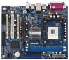
...Ethernet - Micro ATX Form Factor: 9.6-in x 7.8-in, 24.4 cm x 19.8 cm - Supports Hyper-Threading Technology (see CAUTION 5) - ASRock U-COP (see CAUTION 3) - 2 x DDR DIMM slots - shared memory 96MB - Supports Wake-On-LAN ASRock I /O - Dual Channel DDR Memory Technology (see CAUTION 6) - Boot Failure Guard (B.F.G.) - 3 x PCI slots - 1 x AGP ...1 x PS/2 Mouse Port - 1 x PS/2 Keyboard Port - 1 x VGA Port - 1 x Parallel Port (ECP/EPP Support) - 6 x Ready-to-Use USB 2.0 Ports - 1 x RJ-45 Port - Socket 478 for 1.5V 8X/4X AGP card (see CAUTION 7) - 1 x AMR slot - capacity: 2GB -
...Ethernet - Micro ATX Form Factor: 9.6-in x 7.8-in, 24.4 cm x 19.8 cm - Supports Hyper-Threading Technology (see CAUTION 5) - ASRock U-COP (see CAUTION 3) - 2 x DDR DIMM slots - shared memory 96MB - Supports Wake-On-LAN ASRock I /O - Dual Channel DDR Memory Technology (see CAUTION 6) - Boot Failure Guard (B.F.G.) - 3 x PCI slots - 1 x AGP ...1 x PS/2 Mouse Port - 1 x PS/2 Keyboard Port - 1 x VGA Port - 1 x Parallel Port (ECP/EPP Support) - 6 x Ready-to-Use USB 2.0 Ports - 1 x RJ-45 Port - Socket 478 for 1.5V 8X/4X AGP card (see CAUTION 7) - 1 x AMR slot - capacity: 2GB -
User Manual
Page 9
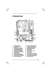
... Intel ICH5 CMOS Battery CLRCMOS0 SATA2 SATA1 USB67 1 IR1 1 CHA_FAN1 PANEL 1 SPEAKER1 PLED PWRBTN 1 1 HDLED RESET 22 21 20 19 18 17 16 P4i65G Prescott800 Dual Channel DDR400 DDR1 (64/72 bit, 184-pin module) DDR2 (64/72 bit, 184-pin module) 24.4cm (9.6 in) 7 8 9... 10 11 12 13 14 15 1 PS2_USB_PWR1 Jumper 2 ATX 12V Connector (ATX12V1) 3 P4-478 CPU Socket 4 CPU Heatsink Retention Module 5 CPU Fan Connector (CPU_FAN1) 6 184-pin DDR DIMM Slots (DDR1- 2) 7 ATX Power Connector (ATXPWR1) 8 Primary IDE Connector (IDE1, Blue...
... Intel ICH5 CMOS Battery CLRCMOS0 SATA2 SATA1 USB67 1 IR1 1 CHA_FAN1 PANEL 1 SPEAKER1 PLED PWRBTN 1 1 HDLED RESET 22 21 20 19 18 17 16 P4i65G Prescott800 Dual Channel DDR400 DDR1 (64/72 bit, 184-pin module) DDR2 (64/72 bit, 184-pin module) 24.4cm (9.6 in) 7 8 9... 10 11 12 13 14 15 1 PS2_USB_PWR1 Jumper 2 ATX 12V Connector (ATX12V1) 3 P4-478 CPU Socket 4 CPU Heatsink Retention Module 5 CPU Fan Connector (CPU_FAN1) 6 184-pin DDR DIMM Slots (DDR1- 2) 7 ATX Power Connector (ATXPWR1) 8 Primary IDE Connector (IDE1, Blue...
User Manual
Page 12
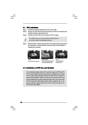
...the CPU fan to dissipate heat. For proper installation, please kindly refer to the instruction manuals of CPU Fan and Heatsink This motherboard adopts 478-pin CPU socket to indicate that it is in place, press it fits in place. It requires larger heatsink and cooling fan to the CPU_FAN connector ...(CPU_FAN1, see page 9, No. 5). Step 2. You also need to spray thermal grease between the CPU and the heatsink to a 90° angle. Unlock the socket by lifting the lever up to improve heat dissipation. Make sure that its marked corner matches the base of the pins. The CPU fits only...
...the CPU fan to dissipate heat. For proper installation, please kindly refer to the instruction manuals of CPU Fan and Heatsink This motherboard adopts 478-pin CPU socket to indicate that it is in place, press it fits in place. It requires larger heatsink and cooling fan to the CPU_FAN connector ...(CPU_FAN1, see page 9, No. 5). Step 2. You also need to spray thermal grease between the CPU and the heatsink to a 90° angle. Unlock the socket by lifting the lever up to improve heat dissipation. Make sure that its marked corner matches the base of the pins. The CPU fits only...
Quick Installation Guide
Page 2
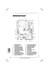
Motherboard Layout English 1 PS2_USB_PWR1 Jumper 2 ATX 12V Connector (ATX12V1) 3 P4-478 CPU Socket 4 CPU Heatsink Retention Module 5 CPU Fan Connector (CPU_FAN1) 6 184-pin DDR DIMM Slots (DDR1- 2) 7 ATX Power Connector (ATXPWR1) 8 Primary IDE Connector (IDE1, Blue) 9 Secondary IDE ... Audio Header (AUDIO1) 27 Internal Audio Connector: AUX1 (White) 28 Internal Audio Connector: CD1 (Black) 29 Shared USB 2.0 Header (USB4_5, Blue) 30 North Bridge Controller 2 ASRock P4i65G Motherboard
Motherboard Layout English 1 PS2_USB_PWR1 Jumper 2 ATX 12V Connector (ATX12V1) 3 P4-478 CPU Socket 4 CPU Heatsink Retention Module 5 CPU Fan Connector (CPU_FAN1) 6 184-pin DDR DIMM Slots (DDR1- 2) 7 ATX Power Connector (ATXPWR1) 8 Primary IDE Connector (IDE1, Blue) 9 Secondary IDE ... Audio Header (AUDIO1) 27 Internal Audio Connector: AUX1 (White) 28 Internal Audio Connector: CD1 (Black) 29 Shared USB 2.0 Header (USB4_5, Blue) 30 North Bridge Controller 2 ASRock P4i65G Motherboard
Quick Installation Guide
Page 5
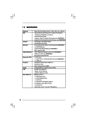
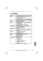
...® ICH5 - CPU Frequency Stepless Control (see CAUTION 3) - 2 x DDR DIMM slots - Cmedia 9761A 5.1 channel audio CODEC - Dual Channel DDR Memory Technology (see CAUTION 5) - DirectX 8.0 VGA - Socket 478 for 1.5V 8X/4X AGP card (see CAUTION 7) - 1 x AMR slot - FSB 800/533/400 MHz - capacity: 2GB - Boot Failure Guard (B.F.G.) - 3 x PCI slots - 1 x AGP...174; 4 / Celeron® D (Prescott, Northwood, Willamate) processors - Integrated Intel® Extreme Graphics 2 - Speed: 10/100 Ethernet - Audio Jack: Line In / Line Out / Microphone English 5 ASRock P4i65G Motherboard
...® ICH5 - CPU Frequency Stepless Control (see CAUTION 3) - 2 x DDR DIMM slots - Cmedia 9761A 5.1 channel audio CODEC - Dual Channel DDR Memory Technology (see CAUTION 5) - DirectX 8.0 VGA - Socket 478 for 1.5V 8X/4X AGP card (see CAUTION 7) - 1 x AMR slot - FSB 800/533/400 MHz - capacity: 2GB - Boot Failure Guard (B.F.G.) - 3 x PCI slots - 1 x AGP...174; 4 / Celeron® D (Prescott, Northwood, Willamate) processors - Integrated Intel® Extreme Graphics 2 - Speed: 10/100 Ethernet - Audio Jack: Line In / Line Out / Microphone English 5 ASRock P4i65G Motherboard
