
User Manual
Page 2
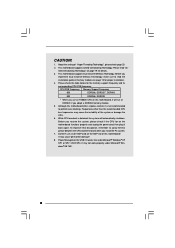
... not provide warranty of any errors or omissions that may be constructed as a commitment by ASRock. CALIFORNIA, USA ONLY The Lithium battery adopted on this manual may cause undesired operation. Copyright Notice: No part of this motherboard contains Perchlorate, a toxic substance controlled in Perchlorate Best Management Practices (BMP) regulations passed by the...
... not provide warranty of any errors or omissions that may be constructed as a commitment by ASRock. CALIFORNIA, USA ONLY The Lithium battery adopted on this manual may cause undesired operation. Copyright Notice: No part of this motherboard contains Perchlorate, a toxic substance controlled in Perchlorate Best Management Practices (BMP) regulations passed by the...
User Manual
Page 3
Contents 1 Introduction 5 1.1 Package Contents 5 1.2 Specifications 6 1.3 Motherboard Layout 9 1.4 ASRock I/O PlusTM 10 2 Installation 11 Pre-installation Precautions 11 2.1 CPU Installation 12 2.2 Installation of CPU Fan and Heatsink 12 2.3 Installation of Memory Modules (DIMM 13 2.4 Expansion ...
Contents 1 Introduction 5 1.1 Package Contents 5 1.2 Specifications 6 1.3 Motherboard Layout 9 1.4 ASRock I/O PlusTM 10 2 Installation 11 Pre-installation Precautions 11 2.1 CPU Installation 12 2.2 Installation of CPU Fan and Heatsink 12 2.3 Installation of Memory Modules (DIMM 13 2.4 Expansion ...
User Manual
Page 5
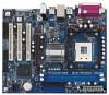
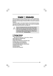
ASRock website http://www.asrock.com 1.1 Package Contents ASRock P4i65G Motherboard (Micro ATX Form Factor: 9.6-in x 7.8-in, 24.4 cm x 19.8 cm) ASRock P4i65G Quick Installation Guide ASRock P4i65G Support CD One 80-conductor Ultra ATA 66/100 IDE Ribbon Cable One Ribbon Cable for purchasing ASRock P4i65G motherboard, a reliable motherboard produced under ASRock's consistently stringent quality control. Because the motherboard specifications and the BIOS software might...
ASRock website http://www.asrock.com 1.1 Package Contents ASRock P4i65G Motherboard (Micro ATX Form Factor: 9.6-in x 7.8-in, 24.4 cm x 19.8 cm) ASRock P4i65G Quick Installation Guide ASRock P4i65G Support CD One 80-conductor Ultra ATA 66/100 IDE Ribbon Cable One Ribbon Cable for purchasing ASRock P4i65G motherboard, a reliable motherboard produced under ASRock's consistently stringent quality control. Because the motherboard specifications and the BIOS software might...
User Manual
Page 8
... Before you implement Dual Channel Memory Technology, make sure to read "Un- Do NOT use an FSB800-CPU on this motherboard, it back again. This motherboard supports Untied Overclocking Technology. Before you use a 3.3V AGP card on page 19 for proper installation. 4. It may ... 533 DDR266, DDR333 * When you resume the system, please check if the CPU fan on page 13 for details. 3. Although this motherboard! Power Management for the memory support frequency and its corresponding CPU FSB frequency. CAUTION! 1. Frequencies other than the recommended CPU bus frequencies...
... Before you implement Dual Channel Memory Technology, make sure to read "Un- Do NOT use an FSB800-CPU on this motherboard, it back again. This motherboard supports Untied Overclocking Technology. Before you use a 3.3V AGP card on page 19 for proper installation. 4. It may ... 533 DDR266, DDR333 * When you resume the system, please check if the CPU fan on page 13 for details. 3. Although this motherboard! Power Management for the memory support frequency and its corresponding CPU FSB frequency. CAUTION! 1. Frequencies other than the recommended CPU bus frequencies...
User Manual
Page 9
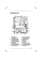
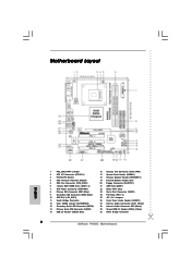
1.3 Motherboard Layout 12 3 45 6 19.8cm (7.8 in) PS2 Mouse 1 PS2_USB_PWR1 PS2 Keyboard CPU_FAN1 VGA1 ATXPWR1 PGA478 PARALLEL PORT 30 29 28 27 26 25 24 23 ... IDE2 IDE1 Intel ICH5 CMOS Battery CLRCMOS0 SATA2 SATA1 USB67 1 IR1 1 CHA_FAN1 PANEL 1 SPEAKER1 PLED PWRBTN 1 1 HDLED RESET 22 21 20 19 18 17 16 P4i65G Prescott800 Dual Channel DDR400 DDR1 (64/72 bit, 184-pin module) DDR2 (64/72 bit, 184-pin module) 24.4cm (9.6 in) 7 8 9 10 11 12 13...
1.3 Motherboard Layout 12 3 45 6 19.8cm (7.8 in) PS2 Mouse 1 PS2_USB_PWR1 PS2 Keyboard CPU_FAN1 VGA1 ATXPWR1 PGA478 PARALLEL PORT 30 29 28 27 26 25 24 23 ... IDE2 IDE1 Intel ICH5 CMOS Battery CLRCMOS0 SATA2 SATA1 USB67 1 IR1 1 CHA_FAN1 PANEL 1 SPEAKER1 PLED PWRBTN 1 1 HDLED RESET 22 21 20 19 18 17 16 P4i65G Prescott800 Dual Channel DDR400 DDR1 (64/72 bit, 184-pin module) DDR2 (64/72 bit, 184-pin module) 24.4cm (9.6 in) 7 8 9 10 11 12 13...
User Manual
Page 11
... the like. Unplug the power cord from the power supply. Failure to the motherboard, peripherals, and/or components. 11 Pre-installation Precautions Take note of your motherboard directly on a grounded antistatic pad or in , 24.4 cm x 19.8 cm) motherboard. Chapter 2 Installation P4i65G is detached from the wall socket before you handle components. 3. Whenever you...
... the like. Unplug the power cord from the power supply. Failure to the motherboard, peripherals, and/or components. 11 Pre-installation Precautions Take note of your motherboard directly on a grounded antistatic pad or in , 24.4 cm x 19.8 cm) motherboard. Chapter 2 Installation P4i65G is detached from the wall socket before you handle components. 3. Whenever you...
User Manual
Page 12
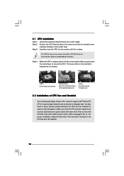
...®4 CPU. You also need to spray thermal grease between the CPU and the heatsink to the instruction manuals of CPU Fan and Heatsink This motherboard adopts 478-pin CPU socket to dissipate heat. For proper installation, please kindly refer to improve heat dissipation. Unlock the socket by lifting the lever...
...®4 CPU. You also need to spray thermal grease between the CPU and the heatsink to the instruction manuals of CPU Fan and Heatsink This motherboard adopts 478-pin CPU socket to dissipate heat. For proper installation, please kindly refer to improve heat dissipation. Unlock the socket by lifting the lever...
User Manual
Page 13
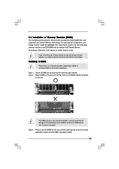
... by pressing the retaining clips outward. Firmly insert the DIMM into the slot at incorrect orientation. 2.3 Installation of Memory Modules (DIMM) This motherboard provides two 184-pin DDR (Double Data Rate) DIMM slots, and supports Dual Channel Memory Technology. notch break notch break The DIMM only .... If you install only one correct orientation. Otherwise, it is properly seated. 13 Step 3. It will cause permanent damage to the motherboard and the DIMM if you always need to install two identical (the same brand, speed, size and chip-type) memory modules in ...
... by pressing the retaining clips outward. Firmly insert the DIMM into the slot at incorrect orientation. 2.3 Installation of Memory Modules (DIMM) This motherboard provides two 184-pin DDR (Double Data Rate) DIMM slots, and supports Dual Channel Memory Technology. notch break notch break The DIMM only .... If you install only one correct orientation. Otherwise, it is properly seated. 13 Step 3. It will cause permanent damage to the motherboard and the DIMM if you always need to install two identical (the same brand, speed, size and chip-type) memory modules in ...
User Manual
Page 14
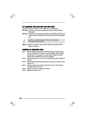
... AGP slot is already installed in a chassis). Please read the documentation of this motherboard. Step 5. Step 4. Step 2. Keep the screws for the card before you intend to use. AMR slot: AMR slot is used to insert an ASRock MR card (optional) with the slot and press firmly until the card is completely...
... AGP slot is already installed in a chassis). Please read the documentation of this motherboard. Step 5. Step 4. Step 2. Keep the screws for the card before you intend to use. AMR slot: AMR slot is used to insert an ASRock MR card (optional) with the slot and press firmly until the card is completely...

User Manual
Page 16
... to 1.5 Gb/s data transfer rate. Besides, to the secondary IDE connector (IDE2, black). Serial ATA (SATA) Data Cable Either end of the motherboard! 2.6 Onboard Headers and Connectors Onboard headers and connectors are NOT jumpers. Please refer to the instruction of the connector. FDD connector (33-pin FLOPPY1)... FLOPPY1 the red-striped side to the IDE devices 80-conductor ATA 66/100 cable Note: If you use only one IDE device on the motherboard. 16 Primary IDE connector (Blue) Secondary IDE connector (Black) (39-pin IDE1, see p.9 No. 8) (39-pin IDE2, see p.9 No. 9) PIN1 ...
... to 1.5 Gb/s data transfer rate. Besides, to the secondary IDE connector (IDE2, black). Serial ATA (SATA) Data Cable Either end of the motherboard! 2.6 Onboard Headers and Connectors Onboard headers and connectors are NOT jumpers. Please refer to the instruction of the connector. FDD connector (33-pin FLOPPY1)... FLOPPY1 the red-striped side to the IDE devices 80-conductor ATA 66/100 cable Note: If you use only one IDE device on the motherboard. 16 Primary IDE connector (Blue) Secondary IDE connector (Black) (39-pin IDE1, see p.9 No. 8) (39-pin IDE2, see p.9 No. 9) PIN1 ...

User Manual
Page 18
... panel audio header may cause permanent damage to this connector so that it is necessary to connect a power supply with ATX 12V plug to this motherboard. Chassis Fan Connector (3-pin CHA_FAN1) (see p.9 No. 18) 1 SPEAKER DUMMY DUMMY +5V Please connect the chassis speaker to this connector and match the black wire...
... panel audio header may cause permanent damage to this connector so that it is necessary to connect a power supply with ATX 12V plug to this motherboard. Chassis Fan Connector (3-pin CHA_FAN1) (see p.9 No. 18) 1 SPEAKER DUMMY DUMMY +5V Please connect the chassis speaker to this connector and match the black wire...
User Manual
Page 19
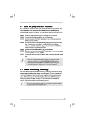
...end of your system. STEP 5: Connect the SATA power cable to the SATA hard disk. 2.7 Serial ATA (SATA) Hard Disks Installation This motherboard adopts Intel ICH5 south bridge chipset that FSB can operate under a more stable overclocking environment. STEP 3: Connect one SATA HDD, the installation ...process is complete at this motherboard for the possible overclocking risk before you just want to install two SATA HDDs, please continue to the secondary SATA hard disk. ...
...end of your system. STEP 5: Connect the SATA power cable to the SATA hard disk. 2.7 Serial ATA (SATA) Hard Disks Installation This motherboard adopts Intel ICH5 south bridge chipset that FSB can operate under a more stable overclocking environment. STEP 3: Connect one SATA HDD, the installation ...process is complete at this motherboard for the possible overclocking risk before you just want to install two SATA HDDs, please continue to the secondary SATA hard disk. ...
User Manual
Page 20
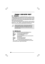
... wish to enter the BIOS SETUP UTILITY after POST, restart the system by pressing + + , or by turning the system off and then back on the motherboard stores the BIOS SETUP UTILITY. Please press during the Power-On-Self-Test (POST) to configure your screen. 3.1.1 BIOS Menu Bar The top of the...
... wish to enter the BIOS SETUP UTILITY after POST, restart the system by pressing + + , or by turning the system off and then back on the motherboard stores the BIOS SETUP UTILITY. Please press during the Power-On-Self-Test (POST) to configure your screen. 3.1.1 BIOS Menu Bar The top of the...
User Manual
Page 22
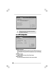
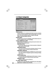
... stability. 22 CPU Host Frequency While entering setup, BIOS auto detects the present CPU host frequency of Boot Failure Guard. Setting wrong values in this motherboard. BIOS SETUP UTILITY Main Advanced H/W Monitor Boot Security Exit Advanced Settings WARNING : Setting wrong values in below sections may cause the system to malfunction. 3.3.1 CPU...
... stability. 22 CPU Host Frequency While entering setup, BIOS auto detects the present CPU host frequency of Boot Failure Guard. Setting wrong values in this motherboard. BIOS SETUP UTILITY Main Advanced H/W Monitor Boot Security Exit Advanced Settings WARNING : Setting wrong values in below sections may cause the system to malfunction. 3.3.1 CPU...
User Manual
Page 24
... item to adjust the means of DRAM clocks for memory compatibility when it is [PCI/AGP]. DRAM CAS# Latency Use this option is selected, the motherboard will detect the memory module(s) inserted and assigns appropriate frequency automatically. Configuration options: [Auto], [2.5], [2], and [3]. tion options: [8 Clocks], [7 Clocks], [6 Clocks], and [5 Clocks]. Graphic Adapter Priority...
... item to adjust the means of DRAM clocks for memory compatibility when it is [PCI/AGP]. DRAM CAS# Latency Use this option is selected, the motherboard will detect the memory module(s) inserted and assigns appropriate frequency automatically. Configuration options: [Auto], [2.5], [2], and [3]. tion options: [8 Clocks], [7 Clocks], [6 Clocks], and [5 Clocks]. Graphic Adapter Priority...
User Manual
Page 25
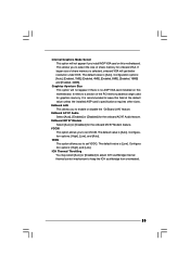
..., 4MB], [Enabled, 8MB], [Enabled, 16MB] and [Enabled, 32MB]. Graphics Aperture Size This option will not appear if there is recommended to leave this motherboard. The default value is [Auto]. If larger size of the PCI memory address range used for onboard VGA. It is no AGP VGA card installed... on this motherboard. OnBoard AC'97 Audio Select [Auto], [Enabled] or [Disabled] for the onboard MC'97 Modem feature. OnBoard MC'97 Modem Select [Auto] ...
..., 4MB], [Enabled, 8MB], [Enabled, 16MB] and [Enabled, 32MB]. Graphics Aperture Size This option will not appear if there is recommended to leave this motherboard. The default value is [Auto]. If larger size of the PCI memory address range used for onboard VGA. It is no AGP VGA card installed... on this motherboard. OnBoard AC'97 Audio Select [Auto], [Enabled] or [Disabled] for the onboard MC'97 Modem feature. OnBoard MC'97 Modem Select [Auto] ...

User Manual
Page 32
... Monitoring Screen In this section, it allows you to monitor the status of the hardware on your system, including the parameters of the CPU temperature, motherboard temperature, CPU fan speed, chassis fan speed, and the critical voltage. BIOS SETUP UTILITY Main Advanced H/W Monitor Boot Security Exit Hardware Health Event Monitoring CPU...
... Monitoring Screen In this section, it allows you to monitor the status of the hardware on your system, including the parameters of the CPU temperature, motherboard temperature, CPU fan speed, chassis fan speed, and the critical voltage. BIOS SETUP UTILITY Main Advanced H/W Monitor Boot Security Exit Hardware Health Event Monitoring CPU...

User Manual
Page 36
...install the necessary drivers to your OS documentation for general reference only. Because motherboard settings and hardware options vary, use the setup procedures in the Support CD to visit ASRock's website at http://www.asrock.com; or you need to contact us or want to know more ... Support CD Information The Support CD that came with the motherboard contains necessary drivers and useful utilities that the motherboard supports. Click on the file "ASSETUP.EXE" from the BIN folder in this chapter for more about ASRock Inc., welcome to display the menus. 4.2.2 Drivers Menu ...
...install the necessary drivers to your OS documentation for general reference only. Because motherboard settings and hardware options vary, use the setup procedures in the Support CD to visit ASRock's website at http://www.asrock.com; or you need to contact us or want to know more ... Support CD Information The Support CD that came with the motherboard contains necessary drivers and useful utilities that the motherboard supports. Click on the file "ASSETUP.EXE" from the BIN folder in this chapter for more about ASRock Inc., welcome to display the menus. 4.2.2 Drivers Menu ...
Quick Installation Guide
Page 1
..., USA ONLY The Lithium battery adopted on this motherboard contains Perchlorate, a toxic substance controlled in advance. This device complies with Part 15 of the FCC Rules. With respect to the contents of this guide, ASRock does not provide warranty of any kind, either .... Operation is subject to the implied warranties or conditions of merchantability or fitness for a particular purpose. All rights reserved. 1 ASRock P4i65G Motherboard English In no responsibility for any errors or omissions that may cause undesired operation. Products and corporate names appearing in this guide ...
..., USA ONLY The Lithium battery adopted on this motherboard contains Perchlorate, a toxic substance controlled in advance. This device complies with Part 15 of the FCC Rules. With respect to the contents of this guide, ASRock does not provide warranty of any kind, either .... Operation is subject to the implied warranties or conditions of merchantability or fitness for a particular purpose. All rights reserved. 1 ASRock P4i65G Motherboard English In no responsibility for any errors or omissions that may cause undesired operation. Products and corporate names appearing in this guide ...
Quick Installation Guide
Page 2
Motherboard Layout English 1 PS2_USB_PWR1 Jumper 2 ATX 12V Connector (ATX12V1) 3 P4-478 CPU Socket 4 CPU Heatsink Retention Module 5 CPU Fan Connector (CPU_FAN1) 6 184-pin DDR DIMM Slots (... Audio Header (AUDIO1) 27 Internal Audio Connector: AUX1 (White) 28 Internal Audio Connector: CD1 (Black) 29 Shared USB 2.0 Header (USB4_5, Blue) 30 North Bridge Controller 2 ASRock P4i65G Motherboard
Motherboard Layout English 1 PS2_USB_PWR1 Jumper 2 ATX 12V Connector (ATX12V1) 3 P4-478 CPU Socket 4 CPU Heatsink Retention Module 5 CPU Fan Connector (CPU_FAN1) 6 184-pin DDR DIMM Slots (... Audio Header (AUDIO1) 27 Internal Audio Connector: AUX1 (White) 28 Internal Audio Connector: CD1 (Black) 29 Shared USB 2.0 Header (USB4_5, Blue) 30 North Bridge Controller 2 ASRock P4i65G Motherboard


