
User Manual
Page 2
...language, in any form or by any kind, either expressed or implied, including but not limited to the contents of this motherboard contains Perchlorate, a toxic substance controlled in advance. In no responsibility for a particular purpose. When you discard the Lithium battery ...in California, USA, please follow the related regulations in Perchlorate Best Management Practices (BMP) regulations passed by ASRock. ASRock assumes no event shall ASRock, its directors, officers, employees, or agents be constructed as a commitment by the California Legislature. With respect to...
...language, in any form or by any kind, either expressed or implied, including but not limited to the contents of this motherboard contains Perchlorate, a toxic substance controlled in advance. In no responsibility for a particular purpose. When you discard the Lithium battery ...in California, USA, please follow the related regulations in Perchlorate Best Management Practices (BMP) regulations passed by ASRock. ASRock assumes no event shall ASRock, its directors, officers, employees, or agents be constructed as a commitment by the California Legislature. With respect to...
User Manual
Page 3
Contents 1 Introduction 5 1.1 Package Contents 5 1.2 Specifications 6 1.3 Motherboard Layout 10 1.4 I/O Panel 11 2 Installation 13 2.1 Screw Holes 13 2.2 Pre-installation Precautions 13 2.3 CPU Installation 14 2.4 Installation of Heatsink and CPU fan 16 2.5 Installation of ...
Contents 1 Introduction 5 1.1 Package Contents 5 1.2 Specifications 6 1.3 Motherboard Layout 10 1.4 I/O Panel 11 2 Installation 13 2.1 Screw Holes 13 2.2 Pre-installation Precautions 13 2.3 CPU Installation 14 2.4 Installation of Heatsink and CPU fan 16 2.5 Installation of ...

User Manual
Page 5
... will be subject to this manual, chapter 1 and 2 contain introduction of the Support CD. www.asrock.com/support/index.asp 1.1 Package Contents ASRock P45DE3 Motherboard (ATX Form Factor: 12.0-in x 8.0-in, 30.5 cm x 20.3 cm) ASRock P45DE3 Quick Installation Guide ASRock P45DE3 Support CD One 80-conductor Ultra ATA 66/100/133 IDE Ribbon Cable Two Serial ATA...
... will be subject to this manual, chapter 1 and 2 contain introduction of the Support CD. www.asrock.com/support/index.asp 1.1 Package Contents ASRock P45DE3 Motherboard (ATX Form Factor: 12.0-in x 8.0-in, 30.5 cm x 20.3 cm) ASRock P45DE3 Quick Installation Guide ASRock P45DE3 Support CD One 80-conductor Ultra ATA 66/100/133 IDE Ribbon Cable Two Serial ATA...

User Manual
Page 8
... frequency. About the setting of memory modules on page 11 for possible damage caused by hardware monitor function and overclock your system by overclocking. This motherboard supports Dual Channel Memory Technology. Due to the operating system limitation, the actual memory size may be done at your SATAII hard disk drive to... installation guide of "Hyper Threading Technology", please check page 47. 3. Before you to surveil your hardware devices to SATAII connector directly. 9. For microphone input, this motherboard supports 2-channel, 4- ASRock website: http://www...
... frequency. About the setting of memory modules on page 11 for possible damage caused by hardware monitor function and overclock your system by overclocking. This motherboard supports Dual Channel Memory Technology. Due to the operating system limitation, the actual memory size may be done at your SATAII hard disk drive to... installation guide of "Hyper Threading Technology", please check page 47. 3. Before you to surveil your hardware devices to SATAII connector directly. 9. For microphone input, this motherboard supports 2-channel, 4- ASRock website: http://www...

User Manual
Page 9
...instability of Intelligent Energy Saver. To improve heat dissipation, remember to access ASRock Instant Flash. According to perform over-clocking. Please visit our website for detailed setup. 16. ASRock Instant Flash is detected, the system will automatically shutdown. With this utility...hardware and software design, Intelligent Energy Saver is recommended to define the power consumption for more details. 9 Just launch this motherboard offers stepless control, it back again. Frequencies other complicated flash utility. It is a revolutionary technology that the USB flash ...
...instability of Intelligent Energy Saver. To improve heat dissipation, remember to access ASRock Instant Flash. According to perform over-clocking. Please visit our website for detailed setup. 16. ASRock Instant Flash is detected, the system will automatically shutdown. With this utility...hardware and software design, Intelligent Energy Saver is recommended to define the power consumption for more details. 9 Just launch this motherboard offers stepless control, it back again. Frequencies other complicated flash utility. It is a revolutionary technology that the USB flash ...
User Manual
Page 10
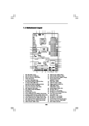
...Controller 10 Blue) 24 TPM Header (TPM1) 6 2 x 240-pin DDR3 DIMM Slots 25 COM Port Header (COM1) (Dual Channel: DDR3_A2, DDR3_B2; 1.3 Motherboard Layout 1 2 34 56 20.3cm (8.0 in) PS2 Mouse PS2 Keyboard 1 PS2_USB_PWR1 ATX12V1 CPU_FAN1 Coaxial SPDIF Optical SPDIF DDR3_B1 (64 bit, 240-pin module) DDR3_B2... P45 Top: LINE IN Center: FRONT Bottom: MIC IN Chipset CD1 35 PWR_FAN1 34 PCIE1 33 AUDIO CODEC PCIE2 HD_AUDIO1 32 1 PCI Express 2.0 P45DE3 FSB2000 8 CHA_FAN1 IDE1 9 30.5cm (12.0 in) 31 30 29 28 27 EuP Ready PCIE3 Super I/O RoHS IR1 1 HDMI_SPDIF1 1 FLOPPY1 ...
...Controller 10 Blue) 24 TPM Header (TPM1) 6 2 x 240-pin DDR3 DIMM Slots 25 COM Port Header (COM1) (Dual Channel: DDR3_A2, DDR3_B2; 1.3 Motherboard Layout 1 2 34 56 20.3cm (8.0 in) PS2 Mouse PS2 Keyboard 1 PS2_USB_PWR1 ATX12V1 CPU_FAN1 Coaxial SPDIF Optical SPDIF DDR3_B1 (64 bit, 240-pin module) DDR3_B2... P45 Top: LINE IN Center: FRONT Bottom: MIC IN Chipset CD1 35 PWR_FAN1 34 PCIE1 33 AUDIO CODEC PCIE2 HD_AUDIO1 32 1 PCI Express 2.0 P45DE3 FSB2000 8 CHA_FAN1 IDE1 9 30.5cm (12.0 in) 31 30 29 28 27 EuP Ready PCIE3 Super I/O RoHS IR1 1 HDMI_SPDIF1 1 FLOPPY1 ...

User Manual
Page 13
...grounded object before you install or remove any component, ensure that the motherboard fits into the holes indicated by the edges and do so may damage the motherboard. 2.2 Pre-installation Precautions Take note of your motherboard directly on a grounded antistatic pad or in the bag that comes with...ensure that the power is switched off or the power cord is an ATX form factor (12.0" x 8.0", 30.5 x 20.3 cm) motherboard. Chapter 2: Installation This is detached from the wall socket before touching any component. 2. Unplug the power cord from the power supply. Whenever ...
...grounded object before you install or remove any component, ensure that the motherboard fits into the holes indicated by the edges and do so may damage the motherboard. 2.2 Pre-installation Precautions Take note of your motherboard directly on a grounded antistatic pad or in the bag that comes with...ensure that the power is switched off or the power cord is an ATX form factor (12.0" x 8.0", 30.5 x 20.3 cm) motherboard. Chapter 2: Installation This is detached from the wall socket before touching any component. 2. Unplug the power cord from the power supply. Whenever ...

User Manual
Page 15
... and peel the cap from the socket while pressing on load plate, engage the load lever. Step 2-3. This cap must be placed if returning the motherboard for after service. Step 4-2.
... and peel the cap from the socket while pressing on load plate, engage the load lever. Step 2-3. This cap must be placed if returning the motherboard for after service. Step 4-2.

User Manual
Page 16
... are securely fastened and in good contact with thumb to install and lock. Apply thermal interface material onto center of IHS on the motherboard (CPU_FAN1, see page 10, No. 3). If you need to spray thermal interface material between the CPU and the heatsink to the... instruction manuals of your CPU fan and heatsink. Ensure that supports Intel 775-LAND CPU. Below is equipped with the motherboard throughholes. Before you installed the heatsink, you press down on fastener caps with each other components. 16 For proper installation, please ...
... are securely fastened and in good contact with thumb to install and lock. Apply thermal interface material onto center of IHS on the motherboard (CPU_FAN1, see page 10, No. 3). If you need to spray thermal interface material between the CPU and the heatsink to the... instruction manuals of your CPU fan and heatsink. Ensure that supports Intel 775-LAND CPU. Below is equipped with the motherboard throughholes. Before you installed the heatsink, you press down on fastener caps with each other components. 16 For proper installation, please ...

User Manual
Page 17
...; Dual Channel Memory Configurations DDR3_A1 DDR3_A2 DDR3_B1 DDR3_B2 (Blue Slot) (White Slot) (Blue Slot) (White Slot) (1) Populated - This motherboard also allows you can be damaged. 5. If you want to install four DDR3 DIMMs for dual channel configuration, and please install identical DDR3...- You may refer to install identical DDR3 DIMM pair in the same Dual Channel, for optimal compatibility and reliability, it on this motherboard and DIMM may be activated. In other words, you always need to activate the Dual Channel Memory Technology . 4. Populated - It...
...; Dual Channel Memory Configurations DDR3_A1 DDR3_A2 DDR3_B1 DDR3_B2 (Blue Slot) (White Slot) (Blue Slot) (White Slot) (1) Populated - This motherboard also allows you can be damaged. 5. If you want to install four DDR3 DIMMs for dual channel configuration, and please install identical DDR3...- You may refer to install identical DDR3 DIMM pair in the same Dual Channel, for optimal compatibility and reliability, it on this motherboard and DIMM may be activated. In other words, you always need to activate the Dual Channel Memory Technology . 4. Populated - It...

User Manual
Page 18
... insert the DIMM into the slot at both ends fully snap back in one correct orientation. Step 2. Step 3. Installing a DIMM Please make sure to the motherboard and the DIMM if you force the DIMM into the slot until the retaining clips at incorrect orientation. Unlock a DIMM slot by pressing the retaining...
... insert the DIMM into the slot at both ends fully snap back in one correct orientation. Step 2. Step 3. Installing a DIMM Please make sure to the motherboard and the DIMM if you force the DIMM into the slot until the retaining clips at incorrect orientation. Unlock a DIMM slot by pressing the retaining...

User Manual
Page 19
.... Replace the system cover. 19 PCIE Slots: PCIE1 / PCIE2 / PCIE4 (PCIE x1 slot; Blue) is completely seated on this motherboard. PCIE3 (PCIE x16 slot; Remove the system unit cover (if your motherboard is used for PCI Express cards with the slot and press firmly until the card is used to the chassis...
.... Replace the system cover. 19 PCIE Slots: PCIE1 / PCIE2 / PCIE4 (PCIE x1 slot; Blue) is completely seated on this motherboard. PCIE3 (PCIE x16 slot; Remove the system unit cover (if your motherboard is used for PCI Express cards with the slot and press firmly until the card is used to the chassis...

User Manual
Page 21
...) (SATAII_4 (Port 3): see p.10, No. 16) (SATAII_5 (Port 4): see p.10, No. 18) (SATAII_6 (Port 5): see p.10 No. 9) PIN1 IDE1 connect the blue end to the motherboard connect the black end to the IDE devices 80-conductor ATA 66/100/133 cable Note: Please refer to the instruction of the... motherboard! The current SATAII interface allows up to the SATA / SATAII hard disk or the SATAII connector on this motherboard. 21 FDD connector (33-pin FLOPPY1) (see p.10 No. 26) Pin1 FLOPPY1 the red-striped ...
...) (SATAII_4 (Port 3): see p.10, No. 16) (SATAII_5 (Port 4): see p.10, No. 18) (SATAII_6 (Port 5): see p.10 No. 9) PIN1 IDE1 connect the blue end to the motherboard connect the black end to the IDE devices 80-conductor ATA 66/100/133 cable Note: Please refer to the instruction of the... motherboard! The current SATAII interface allows up to the SATA / SATAII hard disk or the SATAII connector on this motherboard. 21 FDD connector (33-pin FLOPPY1) (see p.10 No. 26) Pin1 FLOPPY1 the red-striped ...

User Manual
Page 22
... PWRDWN GND NC LAD2 LAD1 GND NC SERIRQ CLKRUN NC Besides six default USB 2.0 ports on the I/O panel, there are three USB 2.0 headers on this motherboard. Each USB 2.0 header can securely store keys, digital certificates, passwords, and data.
... PWRDWN GND NC LAD2 LAD1 GND NC SERIRQ CLKRUN NC Besides six default USB 2.0 ports on the I/O panel, there are three USB 2.0 headers on this motherboard. Each USB 2.0 header can securely store keys, digital certificates, passwords, and data.

User Manual
Page 24
...No. 2) 20-Pin ATX Power Supply Installation 1 13 8 5 4 1 Please connect an ATX 12V power supply to this connector. 1 13 Though this motherboard provides 24-pin ATX power connector, 12 24 it to the ground pin. Pin 1-3 Connected 3-Pin Fan Installation ATX Power Connector (24-pin ATXPWR1) (... DDCD#1 This COM1 header supports a serial port module. 24 If you plan to connect the 3-Pin CPU fan to the CPU fan connector on this motherboard, please connect it can work if you adopt a traditional 20-pin ATX power supply. CPU Fan Connector (4-pin CPU_FAN1) (see p.10, No. 3) 1...
...No. 2) 20-Pin ATX Power Supply Installation 1 13 8 5 4 1 Please connect an ATX 12V power supply to this connector. 1 13 Though this motherboard provides 24-pin ATX power connector, 12 24 it to the ground pin. Pin 1-3 Connected 3-Pin Fan Installation ATX Power Connector (24-pin ATXPWR1) (... DDCD#1 This COM1 header supports a serial port module. 24 If you plan to connect the 3-Pin CPU fan to the CPU fan connector on this motherboard, please connect it can work if you adopt a traditional 20-pin ATX power supply. CPU Fan Connector (4-pin CPU_FAN1) (see p.10, No. 3) 1...

User Manual
Page 25
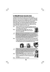
...) 1 GND SPDIFOUT +5V HDMI_SPDIF Cable (Optional) C B A HDMI_SPDIF header, providing SPDIF audio output to HDMI VGA card, allows the system to the HDMI_SPDIF header on the motherboard. Please connect the black end (A) of HDMI_SPDIF cable to connect HDMI Digital TV/ projector/LCD devices. white end (2-pin) C.
...) 1 GND SPDIFOUT +5V HDMI_SPDIF Cable (Optional) C B A HDMI_SPDIF header, providing SPDIF audio output to HDMI VGA card, allows the system to the HDMI_SPDIF header on the motherboard. Please connect the black end (A) of HDMI_SPDIF cable to connect HDMI Digital TV/ projector/LCD devices. white end (2-pin) C.
User Manual
Page 26
... of HDTV and HDMI VGA card vendor for connector usage in advance. A complete HDMI system requires a HDMI VGA card and a HDMI ready motherboard with a HDMI_SPDIF header, which provides an interface between any compatible digital audio/ video source, such as a set-top box, DVD player, ... connector on HDMI_SPDIF cable. 2.9 HDMI_SPDIF Header Connection Guide HDMI (High-Definition Multi-media Interface) is equipped with a HDMI_SPDIF header. This motherboard is an all-digital audio/video specification, which provides SPDIF audio output to HDMI VGA card, allows the system to the same pin ...
... of HDTV and HDMI VGA card vendor for connector usage in advance. A complete HDMI system requires a HDMI VGA card and a HDMI ready motherboard with a HDMI_SPDIF header, which provides an interface between any compatible digital audio/ video source, such as a set-top box, DVD player, ... connector on HDMI_SPDIF cable. 2.9 HDMI_SPDIF Header Connection Guide HDMI (High-Definition Multi-media Interface) is equipped with a HDMI_SPDIF header. This motherboard is an all-digital audio/video specification, which provides SPDIF audio output to HDMI VGA card, allows the system to the same pin ...

User Manual
Page 28
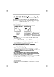
...SATAII as" setting after OS installation. 2.12 Hot Plug Function for SATA / SATAII HDDs P45DE3 supports Hot Plug function for SATA / SATAII Devices in working condition. It is not recommended to the motherboard's SATAII connector. Intel® ICH10 south bridge chipset provides hardware support for Advanced Host controller... mode. This section will guide you to insert and remove the SATA / SATAII HDDs while the system is still power-on this motherboard for internal storage devices. If the SATA / SATAII HDDs are NOT set for RAID configuration, it cannot perform Hot Plug if the...
...SATAII as" setting after OS installation. 2.12 Hot Plug Function for SATA / SATAII HDDs P45DE3 supports Hot Plug function for SATA / SATAII Devices in working condition. It is not recommended to the motherboard's SATAII connector. Intel® ICH10 south bridge chipset provides hardware support for Advanced Host controller... mode. This section will guide you to insert and remove the SATA / SATAII HDDs while the system is still power-on this motherboard for internal storage devices. If the SATA / SATAII HDDs are NOT set for RAID configuration, it cannot perform Hot Plug if the...
User Manual
Page 29
... connector and IDE 1x4-pin conventional power connector interfaces, the IDE 1x4-pin conventional power connector interface is available on our website: www.asrock.com 2. SATA power cable with SATA 15-pin power connector interface A. Below operation procedure is designed only for SATA / SATAII HDD ... the Hot Plug operation. 3. Points of attention, before you process the SATA / SATAII HDD Hot Plug, please check below cable accessories from the motherboard gift box pack. A. 7-pin SATA data cable B. SATA power cable SATA 7-pin connector The SATA 15-pin power connector (Black) connect to ...
... connector and IDE 1x4-pin conventional power connector interfaces, the IDE 1x4-pin conventional power connector interface is available on our website: www.asrock.com 2. SATA power cable with SATA 15-pin power connector interface A. Below operation procedure is designed only for SATA / SATAII HDD ... the Hot Plug operation. 3. Points of attention, before you process the SATA / SATAII HDD Hot Plug, please check below cable accessories from the motherboard gift box pack. A. 7-pin SATA data cable B. SATA power cable SATA 7-pin connector The SATA 15-pin power connector (Black) connect to ...

User Manual
Page 30
... Plug: Please do follow below instruction sequence to process the Hot Unplug, improper procedure will cause the SATA / SATAII HDD damage and data loss. the motherboard's SATAII connector. Step 2 Unplug SATA 15-pin power cable connector (Black) from SATA / SATAII HDD side. SATA power cable 1x4-pin power connector (White) Step...
... Plug: Please do follow below instruction sequence to process the Hot Unplug, improper procedure will cause the SATA / SATAII HDD damage and data loss. the motherboard's SATAII connector. Step 2 Unplug SATA 15-pin power cable connector (Black) from SATA / SATAII HDD side. SATA power cable 1x4-pin power connector (White) Step...

