User Manual
Page 10
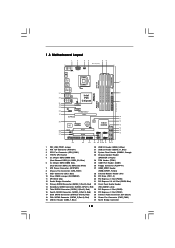
...P45 Top: LINE IN Center: FRONT Bottom: MIC IN Chipset CD1 35 PWR_FAN1 34 PCIE1 33 AUDIO CODEC PCIE2 HD_AUDIO1 32 1 PCI Express 2.0 P45DE3 FSB2000 8 CHA_FAN1 IDE1 9 30.5cm (12.0 in) 31 30 29 28 27 EuP Ready PCIE3 Super I/O RoHS IR1 1 HDMI_SPDIF1 1 ...(USB8_9, Blue) 2 ATX 12V Connector (ATX12V1) 21 USB 2.0 Header (USB10_11, Blue) 3 CPU Fan Connector (CPU_FAN1) 22 System Panel Header (PANEL1, Orange) 4 775-Pin CPU Socket 23 Chassis Speaker Header 5 2 x 240-pin DDR3 DIMM Slots (SPEAKER 1, Purple) (Dual Channel: DDR3_A1, DDR3_B1; Blue) 24 TPM Header (TPM1) 6 2 x...
...P45 Top: LINE IN Center: FRONT Bottom: MIC IN Chipset CD1 35 PWR_FAN1 34 PCIE1 33 AUDIO CODEC PCIE2 HD_AUDIO1 32 1 PCI Express 2.0 P45DE3 FSB2000 8 CHA_FAN1 IDE1 9 30.5cm (12.0 in) 31 30 29 28 27 EuP Ready PCIE3 Super I/O RoHS IR1 1 HDMI_SPDIF1 1 ...(USB8_9, Blue) 2 ATX 12V Connector (ATX12V1) 21 USB 2.0 Header (USB10_11, Blue) 3 CPU Fan Connector (CPU_FAN1) 22 System Panel Header (PANEL1, Orange) 4 775-Pin CPU Socket 23 Chassis Speaker Header 5 2 x 240-pin DDR3 DIMM Slots (SPEAKER 1, Purple) (Dual Channel: DDR3_A1, DDR3_B1; Blue) 24 TPM Header (TPM1) 6 2 x...

User Manual
Page 14
...2. Hold the CPU by depressing down and out on the socket. 2.3 CPU Installation For the installation of Intel 775-LAND CPU, please follow the steps below. 775-Pin Socket Overview Before you insert the 775-LAND CPU into the socket if above situation is any bent pin on the hook to...unclean or if there is found. Pin1 orientation key notch orientation key notch Pin1 alignment key alignment key 775-LAND CPU 775-Pin Socket 14 black line black line Step 1-2. Insert the 775-LAND CPU: Step 2-1. Do not force to fully open position at approximately 135 degrees. Step 1. ...
...2. Hold the CPU by depressing down and out on the socket. 2.3 CPU Installation For the installation of Intel 775-LAND CPU, please follow the steps below. 775-Pin Socket Overview Before you insert the 775-LAND CPU into the socket if above situation is any bent pin on the hook to...unclean or if there is found. Pin1 orientation key notch orientation key notch Pin1 alignment key alignment key 775-LAND CPU 775-Pin Socket 14 black line black line Step 1-2. Insert the 775-LAND CPU: Step 2-1. Do not force to fully open position at approximately 135 degrees. Step 1. ...

User Manual
Page 16
... and lock. 2.4 Installation of CPU Fan and Heatsink This motherboard is an example to illustrate the installation of the heatsink for 775-LAND CPU. Below is equipped with 775-Pin socket that the CPU and the heatsink are oriented on side closest to the CPU fan connector on the motherboard. Apply thermal interface...
... and lock. 2.4 Installation of CPU Fan and Heatsink This motherboard is an example to illustrate the installation of the heatsink for 775-LAND CPU. Below is equipped with 775-Pin socket that the CPU and the heatsink are oriented on side closest to the CPU fan connector on the motherboard. Apply thermal interface...

Quick Installation Guide
Page 2
...Black) 18 Fifth SATAII Connector (SATAII_5 (Port 4), Red) 36 Power Fan Connector (PWR_FAN1) 19 USB 2.0 Header (USB6_7, Blue) 37 North Bridge Controller 2 ASRock P45DE3 Motherboard Blue) 24 TPM Header (TPM1) 6 2 x 240-pin DDR3 DIMM Slots 25 COM Port Header (COM1) (Dual Channel: DDR3_A2, DDR3_B2; Motherboard ...2 ATX 12V Connector (ATX12V1) 21 USB 2.0 Header (USB10_11, Blue) 3 CPU Fan Connector (CPU_FAN1) 22 System Panel Header (PANEL1, Orange) 4 775-Pin CPU Socket 23 Chassis Speaker Header 5 2 x 240-pin DDR3 DIMM Slots (SPEAKER 1, Purple) (Dual Channel: DDR3_A1, DDR3_B1;
...Black) 18 Fifth SATAII Connector (SATAII_5 (Port 4), Red) 36 Power Fan Connector (PWR_FAN1) 19 USB 2.0 Header (USB6_7, Blue) 37 North Bridge Controller 2 ASRock P45DE3 Motherboard Blue) 24 TPM Header (TPM1) 6 2 x 240-pin DDR3 DIMM Slots 25 COM Port Header (COM1) (Dual Channel: DDR3_A2, DDR3_B2; Motherboard ...2 ATX 12V Connector (ATX12V1) 21 USB 2.0 Header (USB10_11, Blue) 3 CPU Fan Connector (CPU_FAN1) 22 System Panel Header (PANEL1, Orange) 4 775-Pin CPU Socket 23 Chassis Speaker Header 5 2 x 240-pin DDR3 DIMM Slots (SPEAKER 1, Purple) (Dual Channel: DDR3_A1, DDR3_B1;

Quick Installation Guide
Page 10
... be seriously damaged. 10 ASRock P45DE3 Motherboard English Hold components by the edges and do not over-tighten the screws! Failure to use a grounded wrist strap or touch a safety grounded object before touching any motherboard settings. 1. Unplug the power cord from the wall socket before you insert the 775-LAND CPU into the screw...
... be seriously damaged. 10 ASRock P45DE3 Motherboard English Hold components by the edges and do not over-tighten the screws! Failure to use a grounded wrist strap or touch a safety grounded object before touching any motherboard settings. 1. Unplug the power cord from the wall socket before you insert the 775-LAND CPU into the screw...

Quick Installation Guide
Page 11
... PnP cap with black lines. Rotate the load plate to assist in removal. 11 ASRock P45DE3 Motherboard English Pin1 orientation key notch orientation key notch Pin1 alignment key alignment key 775-LAND CPU 775-Pin Socket For proper inserting, please ensure to match the two orientation key notches of PnP cap... depressing down and out on center of the CPU with IHS (Integrated Heat Sink) up. Carefully place the CPU into the socket by using a purely vertical motion. Insert the 775-LAND CPU: Step 2-1. black line black line Step 2-2. Step 1. Verify that the CPU is within the...
... PnP cap with black lines. Rotate the load plate to assist in removal. 11 ASRock P45DE3 Motherboard English Pin1 orientation key notch orientation key notch Pin1 alignment key alignment key 775-LAND CPU 775-Pin Socket For proper inserting, please ensure to match the two orientation key notches of PnP cap... depressing down and out on center of the CPU with IHS (Integrated Heat Sink) up. Carefully place the CPU into the socket by using a purely vertical motion. Insert the 775-LAND CPU: Step 2-1. black line black line Step 2-2. Step 1. Verify that the CPU is within the...

Quick Installation Guide
Page 12
.... Step 4. Close the socket: Step 4-1. While pressing down the fasteners without rotating them clockwise, the heatsink cannot be placed if returning the motherboard for 775-LAND CPU. Apply thermal interface material onto center of your CPU fan and heatsink. Step 4. Repeat with ...on the motherboard (CPU_FAN1, see page 2, No. 3). Connect fan header with fan operation or contact other components. 12 ASRock P45DE3 Motherboard English Place the heatsink onto the socket. Step 6. Rotate the load plate onto the IHS. Step 4-3. Step 4-2. 1. Secure excess cable with tie-wrap ...
.... Step 4. Close the socket: Step 4-1. While pressing down the fasteners without rotating them clockwise, the heatsink cannot be placed if returning the motherboard for 775-LAND CPU. Apply thermal interface material onto center of your CPU fan and heatsink. Step 4. Repeat with ...on the motherboard (CPU_FAN1, see page 2, No. 3). Connect fan header with fan operation or contact other components. 12 ASRock P45DE3 Motherboard English Place the heatsink onto the socket. Step 6. Rotate the load plate onto the IHS. Step 4-3. Step 4-2. 1. Secure excess cable with tie-wrap ...