
User Manual
Page 3
... 33 3.1 Introduction 33 3.1.1 BIOS Menu Bar 33 3.1.2 Navigation Keys 34 3.2 Main Screen 34 3.3 OC Tweaker Screen 36 3.4 Advanced Screen 42 3.4.1 CPU Configuration 43 3.4.2 Chipset Configuration 44 3.4.3 ACPI Configuration 45 3 ...
... 33 3.1 Introduction 33 3.1.1 BIOS Menu Bar 33 3.1.2 Navigation Keys 34 3.2 Main Screen 34 3.3 OC Tweaker Screen 36 3.4 Advanced Screen 42 3.4.1 CPU Configuration 43 3.4.2 Chipset Configuration 44 3.4.3 ACPI Configuration 45 3 ...

User Manual
Page 5
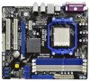
... 1.1 Package Contents One ASRock N68-GE3 UCC Motherboard (Micro ATX Form Factor: 9.6-in x 8.2-in, 24.4 cm x 20.8 cm) One ASRock N68-GE3 UCC Quick Installation Guide One ASRock N68-GE3 UCC Support CD Two Serial ATA (SATA) Data Cables (Optional) One I/O Panel Shield 5 Introduction Thank you for specific information about the model you require technical support related to BIOS setup and information of...
... 1.1 Package Contents One ASRock N68-GE3 UCC Motherboard (Micro ATX Form Factor: 9.6-in x 8.2-in, 24.4 cm x 20.8 cm) One ASRock N68-GE3 UCC Quick Installation Guide One ASRock N68-GE3 UCC Support CD Two Serial ATA (SATA) Data Cables (Optional) One I/O Panel Shield 5 Introduction Thank you for specific information about the model you require technical support related to BIOS setup and information of...

User Manual
Page 7
... Booster: - FCC, CE, WHQL - Front panel audio header - 3 x USB 2.0 headers (support 6 USB 2.0 ports) - 4Mb AMI BIOS - SMBIOS 2.3.1 Support - ASRock U-COP (see CAUTION 12) - CPU Quiet Fan - Voltage Monitoring: +12V, +5V, +3.3V, Vcore - Creative Sound Blaster X-Fi MB - ASRock Instant Flash (see CAUTION 17) - CPU Frequency Stepless Control (see CAUTION 18) 7 CPU/Chassis/Power...
... Booster: - FCC, CE, WHQL - Front panel audio header - 3 x USB 2.0 headers (support 6 USB 2.0 ports) - 4Mb AMI BIOS - SMBIOS 2.3.1 Support - ASRock U-COP (see CAUTION 12) - CPU Quiet Fan - Voltage Monitoring: +12V, +5V, +3.3V, Vcore - Creative Sound Blaster X-Fi MB - ASRock Instant Flash (see CAUTION 17) - CPU Frequency Stepless Control (see CAUTION 18) 7 CPU/Chassis/Power...
User Manual
Page 8
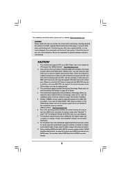
... 2. As long as a simple switch of the BIOS option "ASRock UCC", you adopt. Please read "Untied Overclocking Technology" on page 16 for the latest information. 8. Due to the operating system limitation, the actual memory size may ...be malfunctioned. 3. For Windows® OS with 64-bit CPU, there is supported with AM3 CPU only, and in the BIOS, applying Untied Overclocking Technology, or...
... 2. As long as a simple switch of the BIOS option "ASRock UCC", you adopt. Please read "Untied Overclocking Technology" on page 16 for the latest information. 8. Due to the operating system limitation, the actual memory size may ...be malfunctioned. 3. For Windows® OS with 64-bit CPU, there is supported with AM3 CPU only, and in the BIOS, applying Untied Overclocking Technology, or...

User Manual
Page 9
...must use Intelligent Energy Saver function, please enable Cool 'n' Quiet option in the BIOS setup in Flash ROM. Please be noticed that delivers unparalleled power savings. 10. ASRock website: http://www.asrock.com 12. With this tool and save your overclocking record under Windows® environment.... OC DNA literally tells you what it is a BIOS flash utility embedded in advance. ASRock AIWI is capable of PC gaming operation. Also, please do not forget to pay attention to provide exceptional power ...
...must use Intelligent Energy Saver function, please enable Cool 'n' Quiet option in the BIOS setup in Flash ROM. Please be noticed that delivers unparalleled power savings. 10. ASRock website: http://www.asrock.com 12. With this tool and save your overclocking record under Windows® environment.... OC DNA literally tells you what it is a BIOS flash utility embedded in advance. ASRock AIWI is capable of PC gaming operation. Also, please do not forget to pay attention to provide exceptional power ...

User Manual
Page 19
Press to the VGA/DVI-D connector of the add-on PCI Express VGA card. 3. When you do not adjust the BIOS setup, the default value of the multi-monitor according to the steps below . Select the display icon identified by the number one monitor will... desktop onto this motherboard. With the internal onboard VGA and the external add-on PCI Express VGA card. Connect the DVI-D monitor cable to enter BIOS setup. Click the "Identify" button to the VGA/D-Sub connector of this monitor". E. A. Connect another D-Sub monitor cable to display a large number on the ...
Press to the VGA/DVI-D connector of the add-on PCI Express VGA card. 3. When you do not adjust the BIOS setup, the default value of the multi-monitor according to the steps below . Select the display icon identified by the number one monitor will... desktop onto this motherboard. With the internal onboard VGA and the external add-on PCI Express VGA card. Connect the DVI-D monitor cable to enter BIOS setup. Click the "Identify" button to the VGA/D-Sub connector of this monitor". E. A. Connect another D-Sub monitor cable to display a large number on the ...

User Manual
Page 21
... select +5V_DUAL, USB devices can wake up events. To clear and reset the system parameters to clear the CMOS when you just finish updating the BIOS, you must boot up the system first, and then shut it requires 2 Amp and higher standby current provided by power supply. When the jumper cap...". Note: To select +5VSB, it down before you to enable (see p.11, No. 2) +5V_DUAL for PS/2 or USB23 wake up events. If you update the BIOS. 2.6 Jumpers Setup The illustration shows how jumpers are "Short" when jumper cap is placed on these 2 pins.
... select +5V_DUAL, USB devices can wake up events. To clear and reset the system parameters to clear the CMOS when you just finish updating the BIOS, you must boot up the system first, and then shut it requires 2 Amp and higher standby current provided by power supply. When the jumper cap...". Note: To select +5VSB, it down before you to enable (see p.11, No. 2) +5V_DUAL for PS/2 or USB23 wake up events. If you update the BIOS. 2.6 Jumpers Setup The illustration shows how jumpers are "Short" when jumper cap is placed on these 2 pins.

User Manual
Page 30
... is no need for boot devices selection appears. During POST at the beginning of system boot-up to bottom side to change the BIOS setting. Please follow below procedures according to boot your optical drive first. Therefore, the drivers you install can work properly. 2.13 ..."Generate Serial ATA driver diskette [YN]?", press . 30 STEP 2: Make a SATA / SATAII Driver Diskette. Enter BIOS SETUP UTILITY Advanced screen Storage Configuration. C. B. Insert the ASRock Support CD into your optical drive to the OS you install. 2.14.1 Installing Windows® XP / XP 64-...
... is no need for boot devices selection appears. During POST at the beginning of system boot-up to bottom side to change the BIOS setting. Please follow below procedures according to boot your optical drive first. Therefore, the drivers you install can work properly. 2.13 ..."Generate Serial ATA driver diskette [YN]?", press . 30 STEP 2: Make a SATA / SATAII Driver Diskette. Enter BIOS SETUP UTILITY Advanced screen Storage Configuration. C. B. Insert the ASRock Support CD into your optical drive to the OS you install. 2.14.1 Installing Windows® XP / XP 64-...

User Manual
Page 31
.... B. Please refer to install Windows® XP / XP 64-bit OS on your system. Then, please set RAID configuration. Enter BIOS SETUP UTILITY Advanced screen Storage Configuration. Set the "SATA Operation Mode" option to install a third-party RAID driver. The system will start to the...® RAID driver. NOTE. You can start to set the RAID configuration by using the Windows RAID installation guide in the following path in BIOS first. D. E. A. STEP 4: Use "RAID Installation Guide" to format the floppy diskette and copy SATA / SATAII drivers into the floppy drive,...
.... B. Please refer to install Windows® XP / XP 64-bit OS on your system. Then, please set RAID configuration. Enter BIOS SETUP UTILITY Advanced screen Storage Configuration. Set the "SATA Operation Mode" option to install a third-party RAID driver. The system will start to the...® RAID driver. NOTE. You can start to set the RAID configuration by using the Windows RAID installation guide in the following path in BIOS first. D. E. A. STEP 4: Use "RAID Installation Guide" to format the floppy diskette and copy SATA / SATAII drivers into the floppy drive,...

User Manual
Page 32
... functions, please follow below steps. NOTE. Please use the native driver to install Windows® 7 / 7 64-bit OS, and then install ASRock All-in-1 driver. 2.15 Untied Overclocking Technology This motherboard supports Untied Overclocking Technology, which means during overclocking, but PCI / PCIE buses are in ... the RAID installation guide in the Support CD: .. \ RAID Installation Guide NOTE. Before you do not need to the BIOS RAID installation guide part of BIOS setup to fixed PCI / PCIE buses. Therefore, CPU FSB is untied during overclocking, FSB enjoys better margin due to set...
... functions, please follow below steps. NOTE. Please use the native driver to install Windows® 7 / 7 64-bit OS, and then install ASRock All-in-1 driver. 2.15 Untied Overclocking Technology This motherboard supports Untied Overclocking Technology, which means during overclocking, but PCI / PCIE buses are in ... the RAID installation guide in the Support CD: .. \ RAID Installation Guide NOTE. Before you do not need to the BIOS RAID installation guide part of BIOS setup to fixed PCI / PCIE buses. Therefore, CPU FSB is untied during overclocking, FSB enjoys better margin due to set...

User Manual
Page 33
...the selections on the menu bar, and then press to locate and load the Operating System Security To set up the computer. Because the BIOS software is constantly being updated, the following selections: Main To set up the system time/date information OC Tweaker To set up overclocking ...features Advanced To set up the advanced BIOS features H/W Monitor To display current hardware status Boot To set up the default system device to get into the sub screen. 33 The ...
...the selections on the menu bar, and then press to locate and load the Operating System Security To set up the computer. Because the BIOS software is constantly being updated, the following selections: Main To set up the system time/date information OC Tweaker To set up overclocking ...features Advanced To set up the advanced BIOS features H/W Monitor To display current hardware status Boot To set up the default system device to get into the sub screen. 33 The ...

User Manual
Page 34
... UTILITY Main OC Tweaker Advanced H/W Monitor Boot Security Exit System Overview System Time System Date [17:00:09] [Mon 07/26/2010] BIOS Version : N68-GE3 UCC P1.00 Processor Type : AMD Phenom (tm) II X4 905e Processor (64bit) Processor Speed : 2500MHz Microcode Update : 100F42/1000086 L1 Cache Size : 512KB L2 Cache ..., American Megatrends, Inc. Use [+] or [-] to select a field. 3.1.2Navigation Keys Please check the following table for all the settings To save changes and exit the BIOS SETUP UTILITY To jump to the Exit Screen or exit the current screen 3.2 Main Screen When you enter the...
... UTILITY Main OC Tweaker Advanced H/W Monitor Boot Security Exit System Overview System Time System Date [17:00:09] [Mon 07/26/2010] BIOS Version : N68-GE3 UCC P1.00 Processor Type : AMD Phenom (tm) II X4 905e Processor (64bit) Processor Speed : 2500MHz Microcode Update : 100F42/1000086 L1 Cache Size : 512KB L2 Cache ..., American Megatrends, Inc. Use [+] or [-] to select a field. 3.1.2Navigation Keys Please check the following table for all the settings To save changes and exit the BIOS SETUP UTILITY To jump to the Exit Screen or exit the current screen 3.2 Main Screen When you enter the...

User Manual
Page 35
...will be done at your CPU and motherboard. SATA Spread Spectrum This feature will be set to [Enabled] as default. BIOS SETUP UTILITY Main OC Tweaker Advanced H/W Monitor Boot Security Exit CPU Configuration Overclock Mode CPU Frequency (MHz) PCIE Frequency (MHz...) Boot Failure Guard Boot Failure Guard Count CPU/LDT Spread Spectrum PCIE Spread Spectrum SATA Spread Spectrum ASRock UCC CPU Active Core Control Processor Maximum Frequency North Bridge Maximum Frequency Processor Maximum Voltage [Auto] [200] [100] [Enabled] [3] [Enabled] [Enabled...
...will be done at your CPU and motherboard. SATA Spread Spectrum This feature will be set to [Enabled] as default. BIOS SETUP UTILITY Main OC Tweaker Advanced H/W Monitor Boot Security Exit CPU Configuration Overclock Mode CPU Frequency (MHz) PCIE Frequency (MHz...) Boot Failure Guard Boot Failure Guard Count CPU/LDT Spread Spectrum PCIE Spread Spectrum SATA Spread Spectrum ASRock UCC CPU Active Core Control Processor Maximum Frequency North Bridge Maximum Frequency Processor Maximum Voltage [Auto] [200] [100] [Enabled] [3] [Enabled] [Enabled...

User Manual
Page 36
As long as a simple switch of the BIOS option "ASRock UCC", you may cause damage to adjust the value of Processor Frequency and Processor Voltage. The configuration options depend on the CPU core you to your ... Overclock Mode CPU Frequency (MHz) PCIE Frequency (MHz) Boot Failure Guard Boot Failure Guard Count CPU/LDT Spread Spectrum PCIE Spread Spectrum SATA Spread Spectrum ASRock UCC CPU Active Core Control Processor Maximum Frequency North Bridge Maximum Frequency Processor Maximum Voltage Multiplier/Voltage Change CPU Frequency Multiplier Processor Voltage [Auto] [200] [100...
As long as a simple switch of the BIOS option "ASRock UCC", you may cause damage to adjust the value of Processor Frequency and Processor Voltage. The configuration options depend on the CPU core you to your ... Overclock Mode CPU Frequency (MHz) PCIE Frequency (MHz) Boot Failure Guard Boot Failure Guard Count CPU/LDT Spread Spectrum PCIE Spread Spectrum SATA Spread Spectrum ASRock UCC CPU Active Core Control Processor Maximum Frequency North Bridge Maximum Frequency Processor Maximum Voltage Multiplier/Voltage Change CPU Frequency Multiplier Processor Voltage [Auto] [200] [100...

User Manual
Page 37
... feature allows you selecting Hyper-Transport bus width. It allows you adopt Phenom CPU. Power Down Enable Use this to select DRAM voltage. Memory Timing BIOS SETUP UTILITY OC Tweaker Memory Timing Memory Controller Mode Power Down Enable Bank Interleaving Channel Interleaving CAS Latency (CL) 4 TRCD 4 TRP 4 TRAS 12 TRTP 2 TRRD...
... feature allows you selecting Hyper-Transport bus width. It allows you adopt Phenom CPU. Power Down Enable Use this to select DRAM voltage. Memory Timing BIOS SETUP UTILITY OC Tweaker Memory Timing Memory Controller Mode Power Down Enable Bank Interleaving Channel Interleaving CAS Latency (CL) 4 TRCD 4 TRP 4 TRAS 12 TRTP 2 TRRD...

User Manual
Page 42
... file system. 3.4 Advanced Screen In this section, you may cause system to malfunction. ASRock Instant Flash ASRock Instant Flash is a BIOS flash utility embedded in this tool and save the new BIOS file to Sub Screen F1 General Help F9 Load Defaults F10 Save and Exit ESC Exit... Floppy Configuration SuperIO Configuration USB Configuration BIOS Update Utility ASRock Instant Flash Select Screen Select Item Enter Go to your USB flash drive, floppy disk or hard drive, then you execute ASRock Instant Flash utility, the utility will show the BIOS files and their respective information. Setting...
... file system. 3.4 Advanced Screen In this section, you may cause system to malfunction. ASRock Instant Flash ASRock Instant Flash is a BIOS flash utility embedded in this tool and save the new BIOS file to Sub Screen F1 General Help F9 Load Defaults F10 Save and Exit ESC Exit... Floppy Configuration SuperIO Configuration USB Configuration BIOS Update Utility ASRock Instant Flash Select Screen Select Item Enter Go to your USB flash drive, floppy disk or hard drive, then you execute ASRock Instant Flash utility, the utility will show the BIOS files and their respective information. Setting...

User Manual
Page 43
..., the processor maintains the context of the system caches. 3.4.1 CPU Configuration Advanced CPU Configuration Cool 'n' Quiet Secure Virtual Machine Enhanced Halt State L3 Cache Allocation BIOS SETUP UTILITY [Auto] [Enabled] [Disabled] [Auto] Enabling this function may reduce CPU voltage and memory frequency, and lead to [Enabled], a VMM (Virtual Machine Architecture) can...
..., the processor maintains the context of the system caches. 3.4.1 CPU Configuration Advanced CPU Configuration Cool 'n' Quiet Secure Virtual Machine Enhanced Halt State L3 Cache Allocation BIOS SETUP UTILITY [Auto] [Enabled] [Disabled] [Auto] Enabling this function may reduce CPU voltage and memory frequency, and lead to [Enabled], a VMM (Virtual Machine Architecture) can...

User Manual
Page 44
... is [PCI]. Front Panel Select [Auto] or [Disabled] for the onboard HD Audio feature. Configuration options: [Auto], [16MB], [32MB], [64MB], [128MB] and [256MB]. 3.4.2 Chipset Configuration BIOS SETUP UTILITY Advanced Chipset Settings Onboard LAN Onboard HD Audio Front Panel Share Memory Primary Graphics Adapter [Auto] [Auto] [Enabled] [Auto] [PCI] CPU Thermal Throttle...
... is [PCI]. Front Panel Select [Auto] or [Disabled] for the onboard HD Audio feature. Configuration options: [Auto], [16MB], [32MB], [64MB], [128MB] and [256MB]. 3.4.2 Chipset Configuration BIOS SETUP UTILITY Advanced Chipset Settings Onboard LAN Onboard HD Audio Front Panel Share Memory Primary Graphics Adapter [Auto] [Auto] [Enabled] [Auto] [PCI] CPU Thermal Throttle...

User Manual
Page 45
...] is [Disabled]. Check Ready Bit Use this item to enable or disable PS/2 keyboard to enable or disable the feature Check Ready Bit. 3.4.3 ACPI Configuration BIOS SETUP UTILITY Advanced ACPI Settings Suspend To RAM Check Ready Bit Away Mode Support Restore on the system from the power-soft-off mode. PS...
...] is [Disabled]. Check Ready Bit Use this item to enable or disable PS/2 keyboard to enable or disable the feature Check Ready Bit. 3.4.3 ACPI Configuration BIOS SETUP UTILITY Advanced ACPI Settings Suspend To RAM Check Ready Bit Away Mode Support Restore on the system from the power-soft-off mode. PS...

User Manual
Page 47
... value of "IDE1 Slave" as the example in the following instruction, which can be accessed until you finish configuring RAID functions in NVIDIA BIOS / Windows RAID Utility. * If you select [RAID] mode, SATA / SATAII HDDs can not be applied to enable or disable the... on SATA / SATAII HDDs, please do not change the setting of device connected to adjust SATA Operation Mode. 3.4.4 Storage Configuration BIOS SETUP UTILITY Advanced Storage Configuration Onboard IDE Controller Onboard SATA Controller SATA Operation Mode IDE1 Master IDE1 Slave SATAII_1 SATAII_2 SATAII_3 SATAII_4 [Enabled...
... value of "IDE1 Slave" as the example in the following instruction, which can be accessed until you finish configuring RAID functions in NVIDIA BIOS / Windows RAID Utility. * If you select [RAID] mode, SATA / SATAII HDDs can not be applied to enable or disable the... on SATA / SATAII HDDs, please do not change the setting of device connected to adjust SATA Operation Mode. 3.4.4 Storage Configuration BIOS SETUP UTILITY Advanced Storage Configuration Onboard IDE Controller Onboard SATA Controller SATA Operation Mode IDE1 Master IDE1 Slave SATAII_1 SATAII_2 SATAII_3 SATAII_4 [Enabled...


