
User Manual
Page 2
...cause harmful interference, and (2) this device must accept any interference received, including interference that may appear in this manual. ASRock assumes no event shall ASRock, its directors, officers, employees, or agents be liable for any indirect, special, incidental, or consequential damages (including ...damages arising from any defect or error in the manual or product. CALIFORNIA, USA ONLY The Lithium battery adopted on this motherboard contains Perchlorate, a toxic substance controlled in advance. Copyright Notice: No part of this manual may be reproduced, transcribed,...
...cause harmful interference, and (2) this device must accept any interference received, including interference that may appear in this manual. ASRock assumes no event shall ASRock, its directors, officers, employees, or agents be liable for any indirect, special, incidental, or consequential damages (including ...damages arising from any defect or error in the manual or product. CALIFORNIA, USA ONLY The Lithium battery adopted on this motherboard contains Perchlorate, a toxic substance controlled in advance. Copyright Notice: No part of this manual may be reproduced, transcribed,...

User Manual
Page 3
... Keys 34 3.2 Main Screen 34 3.3 OC Tweaker Screen 36 3.4 Advanced Screen 42 3.4.1 CPU Configuration 43 3.4.2 Chipset Configuration 44 3.4.3 ACPI Configuration 45 3 Introduction 5 1.1 Package Contents 5 1.2 Specifications 6 1.3 Motherboard Layout 11 1.4 I/O Panel 12 2 . Installation 14 Pre-installation Precautions 14 2.1 CPU Installation 15 2.2 Installation of CPU Fan and Heatsink 15 2.3 Installation of Memory Modules (DIMM...
... Keys 34 3.2 Main Screen 34 3.3 OC Tweaker Screen 36 3.4 Advanced Screen 42 3.4.1 CPU Configuration 43 3.4.2 Chipset Configuration 44 3.4.3 ACPI Configuration 45 3 Introduction 5 1.1 Package Contents 5 1.2 Specifications 6 1.3 Motherboard Layout 11 1.4 I/O Panel 12 2 . Installation 14 Pre-installation Precautions 14 2.1 CPU Installation 15 2.2 Installation of CPU Fan and Heatsink 15 2.3 Installation of Memory Modules (DIMM...

User Manual
Page 5
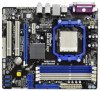
It delivers excellent performance with robust design conforming to ASRock's commitment to change without further notice. www.asrock.com/support/index.asp 1.1 Package Contents One ASRock N68-GE3 UCC Motherboard (Micro ATX Form Factor: 9.6-in x 8.2-in, 24.4 cm x 20.8 cm) One ASRock N68-GE3 UCC Quick Installation Guide One ASRock N68-GE3 UCC Support CD Two Serial ATA (SATA) Data Cables (Optional) One I/O Panel Shield 5 Introduction...
It delivers excellent performance with robust design conforming to ASRock's commitment to change without further notice. www.asrock.com/support/index.asp 1.1 Package Contents One ASRock N68-GE3 UCC Motherboard (Micro ATX Form Factor: 9.6-in x 8.2-in, 24.4 cm x 20.8 cm) One ASRock N68-GE3 UCC Quick Installation Guide One ASRock N68-GE3 UCC Support CD Two Serial ATA (SATA) Data Cables (Optional) One I/O Panel Shield 5 Introduction...
User Manual
Page 8
* For detailed product information, please visit our website: http://www.asrock.com WARNING Please realize that UCC feature is supported with 64-bit CPU, there is no such limitation. 7. This motherboard supports Dual Channel Memory Technology. If you can enjoy the upgrade CPU performance with a better ...setting in addition, not every AM3 CPU can also increase L3 cache size up to read the installation guide of the BIOS option "ASRock UCC", you adopt. Due to SATAII connector, please read "Untied Overclocking Technology" on our website for proper installation. 5. It should ...
* For detailed product information, please visit our website: http://www.asrock.com WARNING Please realize that UCC feature is supported with 64-bit CPU, there is no such limitation. 7. This motherboard supports Dual Channel Memory Technology. If you can enjoy the upgrade CPU performance with a better ...setting in addition, not every AM3 CPU can also increase L3 cache size up to read the installation guide of the BIOS option "ASRock UCC", you adopt. Due to SATAII connector, please read "Untied Overclocking Technology" on our website for proper installation. 5. It should ...

User Manual
Page 9
... your USB flash drive, floppy disk or hard drive, then you the most up-do is just to install the ASRock AIWI utility either from ASRock official website or ASRock software support CD to your motherboard, and also download the free AIWI Lite from App store to your system by... advance. Please visit our website for the operation procedures of PC gaming operation. Please be shared and worked on the same motherboard. 14. ASRock website: http://www.asrock.com 12. OC DNA literally tells you to save your OC settings as yours! Featuring an advanced proprietary hardware and software ...
... your USB flash drive, floppy disk or hard drive, then you the most up-do is just to install the ASRock AIWI utility either from ASRock official website or ASRock software support CD to your motherboard, and also download the free AIWI Lite from App store to your system by... advance. Please visit our website for the operation procedures of PC gaming operation. Please be shared and worked on the same motherboard. 14. ASRock website: http://www.asrock.com 12. OC DNA literally tells you to save your OC settings as yours! Featuring an advanced proprietary hardware and software ...

User Manual
Page 10
... quickly from your computer and up to Intel's suggestion, the EuP ready power supply must meet EuP standard, an EuP ready motherboard and an EuP ready power supply are required. Before you can easily enjoy the marvelous charging experience than the recommended CPU bus ...even supports continuous charging when your Apple devices, such as iPhone/iPod/iPad Touch, ASRock has prepared a wonderful solution for you checking with the power supply manufacturer for the completed system. Although this motherboard offers stepless control, it is not recommended to RAM (S3), hibernation mode (S4...
... quickly from your computer and up to Intel's suggestion, the EuP ready power supply must meet EuP standard, an EuP ready motherboard and an EuP ready power supply are required. Before you can easily enjoy the marvelous charging experience than the recommended CPU bus ...even supports continuous charging when your Apple devices, such as iPhone/iPod/iPad Touch, ASRock has prepared a wonderful solution for you checking with the power supply manufacturer for the completed system. Although this motherboard offers stepless control, it is not recommended to RAM (S3), hibernation mode (S4...

User Manual
Page 14
... a grounded wrist strap or touch a safety grounded object before you install or remove any component. 2. Before you install motherboard components or change any component, place it . Failure to do so may damage the motherboard. 14 Hold components by the edges and do not over-tighten the screws! Whenever you handle components. 3. Unplug...
... a grounded wrist strap or touch a safety grounded object before you install or remove any component. 2. Before you install motherboard components or change any component, place it . Failure to do so may damage the motherboard. 14 Hold components by the edges and do not over-tighten the screws! Whenever you handle components. 3. Unplug...

User Manual
Page 15
Unlock the socket by lifting the lever up to the CPU FAN connector (CPU_FAN1, see Page 11, No. 6). DO NOT force the CPU into this motherboard, it is locked. Then connect the CPU fan to a 90o angle. Step 2. The CPU fits only in good contact with a small triangle. Make sure that ...
Unlock the socket by lifting the lever up to the CPU FAN connector (CPU_FAN1, see Page 11, No. 6). DO NOT force the CPU into this motherboard, it is locked. Then connect the CPU fan to a 90o angle. Step 2. The CPU fits only in good contact with a small triangle. Make sure that ...

User Manual
Page 16
... memory modules are installed in Dual Channel A (DDR3_A1 and DDR3_B1; see p.11 No.8), so that Dual Channel Memory Technology can be damaged. 5. This motherboard also allows you to install four DDR3 DIMMs for example, installing a pair of white slots (DDR3_A2 and DDR3_B2). 2. In other words, you adopt DDR3... in DDR3_A1 and DDR3_A2, it is recommended to install identical DDR3 DIMM pair in the DDR3 DIMM slots on this motherboard, it is recommended to install them on this motherboard, it is unable to install a DDR or DDR2 memory module into DDR3 slot; If you always need to the...
... memory modules are installed in Dual Channel A (DDR3_A1 and DDR3_B1; see p.11 No.8), so that Dual Channel Memory Technology can be damaged. 5. This motherboard also allows you to install four DDR3 DIMMs for example, installing a pair of white slots (DDR3_A2 and DDR3_B2). 2. In other words, you adopt DDR3... in DDR3_A1 and DDR3_A2, it is recommended to install identical DDR3 DIMM pair in the DDR3 DIMM slots on this motherboard, it is recommended to install them on this motherboard, it is unable to install a DDR or DDR2 memory module into DDR3 slot; If you always need to the...

User Manual
Page 17
... outward. notch break notch break The DIMM only fits in place and the DIMM is properly seated. 17 Installing a DIMM Please make sure to the motherboard and the DIMM if you force the DIMM into the slot until the retaining clips at incorrect orientation.
... outward. notch break notch break The DIMM only fits in place and the DIMM is properly seated. 17 Installing a DIMM Please make sure to the motherboard and the DIMM if you force the DIMM into the slot until the retaining clips at incorrect orientation.

User Manual
Page 18
PCI slots: PCI slots are 2 PCI slots and 2 PCI Express slots on the slot. PCIE slots: PCIE1 (PCIE x1 slot) is completely seated on this motherboard. Step 2. Installing an expansion card Step 1. Step 3. Align the card connector with x1 lane width cards, such as Gigabit LAN card, SATA2 card, etc. Step 4. ...
PCI slots: PCI slots are 2 PCI slots and 2 PCI Express slots on the slot. PCIE slots: PCIE1 (PCIE x1 slot) is completely seated on this motherboard. Step 2. Installing an expansion card Step 1. Step 3. Align the card connector with x1 lane width cards, such as Gigabit LAN card, SATA2 card, etc. Step 4. ...

User Manual
Page 19
..." button to your primary monitor, and then select "Primary". C. Click "Extend my Windows desktop onto this motherboard. 4. Click the number "2" icon. 19 Connect the D-Sub monitor cable to the VGA/DVI-D connector of this motherboard. Connect the DVI-D monitor cable to the VGA/D-Sub port on the I/O panel of the add-on... inserted to be designated as appropriate for the second monitor. D. Right-click the display icon and select "Attached", if necessary. 2.5 Easy Multi Monitor Feature This motherboard supports Multi Monitor upgrade.
..." button to your primary monitor, and then select "Primary". C. Click "Extend my Windows desktop onto this motherboard. 4. Click the number "2" icon. 19 Connect the D-Sub monitor cable to the VGA/DVI-D connector of this motherboard. Connect the DVI-D monitor cable to the VGA/D-Sub port on the I/O panel of the add-on... inserted to be designated as appropriate for the second monitor. D. Right-click the display icon and select "Attached", if necessary. 2.5 Easy Multi Monitor Feature This motherboard supports Multi Monitor upgrade.

User Manual
Page 22
...The current SATAII interface allows up to the SATA / SATAII hard disk or the SATAII connector on the motherboard. 22 Do NOT place jumper caps over the headers and connectors will cause permanent damage of the motherboard! • Floppy Connector (33-pin FLOPPY1) (see p.11 No. 24) Pin1 FLOPPY1 the red...0.1): see p.11, No. 14) (SATAII_3 (PORT 1.0): see p.11, No. 12) (SATAII_4 (PORT 1.1): see p.11 No. 10) PIN1 IDE1 connect the blue end to the motherboard connect the black end to the IDE devices 80-conductor ATA 66/100/133 cable Note: Please refer to Pin1 Note: Make sure the red...
...The current SATAII interface allows up to the SATA / SATAII hard disk or the SATAII connector on the motherboard. 22 Do NOT place jumper caps over the headers and connectors will cause permanent damage of the motherboard! • Floppy Connector (33-pin FLOPPY1) (see p.11 No. 24) Pin1 FLOPPY1 the red...0.1): see p.11, No. 14) (SATAII_3 (PORT 1.0): see p.11, No. 12) (SATAII_4 (PORT 1.1): see p.11 No. 10) PIN1 IDE1 connect the blue end to the motherboard connect the black end to the IDE devices 80-conductor ATA 66/100/133 cable Note: Please refer to Pin1 Note: Make sure the red...

User Manual
Page 23
... p.11 No. 19) USB_PWR P-9 P+9 GND DUMMY 1 GND P+8 P-8 USB_PWR USB_PWR P-7 P+7 GND DUMMY 1 GND P+6 P-6 USB_PWR USB_PWR P-5 P+5 GND DUMMY 1 GND P+4 P-4 USB_PWR Besides four default USB 2.0 ports on this motherboard. Connect Ground (GND) to OUT2_L. MIC_RET and OUT_RET are three USB 2.0 headers on the I/O panel, there are for AC'97 audio panel. 23 You don...
... p.11 No. 19) USB_PWR P-9 P+9 GND DUMMY 1 GND P+8 P-8 USB_PWR USB_PWR P-7 P+7 GND DUMMY 1 GND P+6 P-6 USB_PWR USB_PWR P-5 P+5 GND DUMMY 1 GND P+4 P-4 USB_PWR Besides four default USB 2.0 ports on this motherboard. Connect Ground (GND) to OUT2_L. MIC_RET and OUT_RET are three USB 2.0 headers on the I/O panel, there are for AC'97 audio panel. 23 You don...

User Manual
Page 24
... Power Supply Installation 1 13 24 Please connect the fan cables to the fan connectors and match the black wire to this connector. 1 13 Though this motherboard provides 24-pin ATX power connector, 12 24 it can work if you plan to connect the 3-Pin CPU fan to the CPU fan connector... on this motherboard, please connect it to this motherboard provides 4-Pin CPU fan (Quiet Fan) support, the 3-Pin CPU fan still can still work successfully even without the fan speed control...
... Power Supply Installation 1 13 24 Please connect the fan cables to the fan connectors and match the black wire to this connector. 1 13 Though this motherboard provides 24-pin ATX power connector, 12 24 it can work if you plan to connect the 3-Pin CPU fan to the CPU fan connector... on this motherboard, please connect it to this motherboard provides 4-Pin CPU fan (Quiet Fan) support, the 3-Pin CPU fan still can still work successfully even without the fan speed control...

User Manual
Page 27
... configuration, it is called "Hot Swap" for the action to insert and remove the SATA / SATAII HDDs while the system is still power-on this motherboard for SATA / SATAII Devices. You may install SATA / SATAII hard disks on and in working condition. 2 . 9 Serial ATA (SATA) / Serial ATAII (...SATAII) Hard Disks Installation This motherboard adopts NVIDIA® GeForce 7025 / nForce 630a chipset that it cannot perform Hot Plug if the OS has been installed into the drive bays of...
... configuration, it is called "Hot Swap" for the action to insert and remove the SATA / SATAII HDDs while the system is still power-on this motherboard for SATA / SATAII Devices. You may install SATA / SATAII hard disks on and in working condition. 2 . 9 Serial ATA (SATA) / Serial ATAII (...SATAII) Hard Disks Installation This motherboard adopts NVIDIA® GeForce 7025 / nForce 630a chipset that it cannot perform Hot Plug if the OS has been installed into the drive bays of...

User Manual
Page 28
...sure to power supply Caution 1. SATA power cable with SATA 15-pin power connector interface A. Please follow below operation guide of our motherboard is installed into system properly. Even some SATA / SATAII HDDs provide both SATA 15-pin power connector and IDE 1x4-pin conventional ... connector interfaces, the IDE 1x4-pin conventional power connector interface is available on our website: www.asrock.com 2. Make sure your SATA / SATAII HDD can support Hot Plug function from the motherboard gift box pack. 2.11 SATA / SATAII HDD Hot Plug Feature and Operation Guide This...
...sure to power supply Caution 1. SATA power cable with SATA 15-pin power connector interface A. Please follow below operation guide of our motherboard is installed into system properly. Even some SATA / SATAII HDDs provide both SATA 15-pin power connector and IDE 1x4-pin conventional ... connector interfaces, the IDE 1x4-pin conventional power connector interface is available on our website: www.asrock.com 2. Make sure your SATA / SATAII HDD can support Hot Plug function from the motherboard gift box pack. 2.11 SATA / SATAII HDD Hot Plug Feature and Operation Guide This...

User Manual
Page 29
... will cause the SATA / SATAII HDD damage and data loss. Step 2 Unplug SATA 15-pin power cable connector (Black) from SATA / SATAII HDD side. the motherboard's SATAII connector. Step 4 Connect SATA data cable to the SATA / SATAII HDD.
... will cause the SATA / SATAII HDD damage and data loss. Step 2 Unplug SATA 15-pin power cable connector (Black) from SATA / SATAII HDD side. the motherboard's SATAII connector. Step 4 Connect SATA data cable to the SATA / SATAII HDD.

User Manual
Page 32
... and want to the BIOS RAID installation guide part of BIOS setup to set the selection from [Auto] to load RAID driver from ASRock support CD. Therefore, CPU FSB is untied during overclocking, FSB enjoys better margin due to check the RAID installation guide in the Support... PCIE, Async.]. NOTE. Please use the native driver to install Windows® 7 / 7 64-bit OS, and then install ASRock All-in-1 driver. 2.15 Untied Overclocking Technology This motherboard supports Untied Overclocking Technology, which means during overclocking, but PCI / PCIE buses are in the fixed mode so that FSB can...
... and want to the BIOS RAID installation guide part of BIOS setup to set the selection from [Auto] to load RAID driver from ASRock support CD. Therefore, CPU FSB is untied during overclocking, FSB enjoys better margin due to check the RAID installation guide in the Support... PCIE, Async.]. NOTE. Please use the native driver to install Windows® 7 / 7 64-bit OS, and then install ASRock All-in-1 driver. 2.15 Untied Overclocking Technology This motherboard supports Untied Overclocking Technology, which means during overclocking, but PCI / PCIE buses are in the fixed mode so that FSB can...

User Manual
Page 33
... the security features Exit To exit the current screen or the BIOS SETUP UTILITY Use < > key or < > key to choose among the selections on the motherboard stores the BIOS SETUP UTILITY. The SPI Memory on the menu bar, and then press to configure your system. 3.
... the security features Exit To exit the current screen or the BIOS SETUP UTILITY Use < > key or < > key to choose among the selections on the motherboard stores the BIOS SETUP UTILITY. The SPI Memory on the menu bar, and then press to configure your system. 3.

